EP1441896B1 - Verfahren und vorrichtung zum transportieren von vorformlingen aus einer spritzgiess-einheit zu einer streckblasvorrichtung - Google Patents
Verfahren und vorrichtung zum transportieren von vorformlingen aus einer spritzgiess-einheit zu einer streckblasvorrichtung Download PDFInfo
- Publication number
- EP1441896B1 EP1441896B1 EP02754040A EP02754040A EP1441896B1 EP 1441896 B1 EP1441896 B1 EP 1441896B1 EP 02754040 A EP02754040 A EP 02754040A EP 02754040 A EP02754040 A EP 02754040A EP 1441896 B1 EP1441896 B1 EP 1441896B1
- Authority
- EP
- European Patent Office
- Prior art keywords
- parisons
- group
- injection
- interval
- station
- Prior art date
- Legal status (The legal status is an assumption and is not a legal conclusion. Google has not performed a legal analysis and makes no representation as to the accuracy of the status listed.)
- Expired - Lifetime
Links
Images



Classifications
-
- B—PERFORMING OPERATIONS; TRANSPORTING
- B29—WORKING OF PLASTICS; WORKING OF SUBSTANCES IN A PLASTIC STATE IN GENERAL
- B29C—SHAPING OR JOINING OF PLASTICS; SHAPING OF MATERIAL IN A PLASTIC STATE, NOT OTHERWISE PROVIDED FOR; AFTER-TREATMENT OF THE SHAPED PRODUCTS, e.g. REPAIRING
- B29C49/00—Blow-moulding, i.e. blowing a preform or parison to a desired shape within a mould; Apparatus therefor
- B29C49/42—Component parts, details or accessories; Auxiliary operations
- B29C49/4205—Handling means, e.g. transfer, loading or discharging means
- B29C49/42093—Transporting apparatus, e.g. slides, wheels or conveyors
- B29C49/42101—Conveyors, e.g. flat conveyor or clamping between two bands
-
- B—PERFORMING OPERATIONS; TRANSPORTING
- B29—WORKING OF PLASTICS; WORKING OF SUBSTANCES IN A PLASTIC STATE IN GENERAL
- B29C—SHAPING OR JOINING OF PLASTICS; SHAPING OF MATERIAL IN A PLASTIC STATE, NOT OTHERWISE PROVIDED FOR; AFTER-TREATMENT OF THE SHAPED PRODUCTS, e.g. REPAIRING
- B29C49/00—Blow-moulding, i.e. blowing a preform or parison to a desired shape within a mould; Apparatus therefor
- B29C49/02—Combined blow-moulding and manufacture of the preform or the parison
- B29C49/06—Injection blow-moulding
- B29C49/061—Injection blow-moulding with parison holding means displaceable between injection and blow stations
- B29C49/062—Injection blow-moulding with parison holding means displaceable between injection and blow stations following an arcuate path, e.g. rotary or oscillating-type
-
- B—PERFORMING OPERATIONS; TRANSPORTING
- B29—WORKING OF PLASTICS; WORKING OF SUBSTANCES IN A PLASTIC STATE IN GENERAL
- B29C—SHAPING OR JOINING OF PLASTICS; SHAPING OF MATERIAL IN A PLASTIC STATE, NOT OTHERWISE PROVIDED FOR; AFTER-TREATMENT OF THE SHAPED PRODUCTS, e.g. REPAIRING
- B29C49/00—Blow-moulding, i.e. blowing a preform or parison to a desired shape within a mould; Apparatus therefor
- B29C49/42—Component parts, details or accessories; Auxiliary operations
- B29C49/76—Neck calibration
-
- B—PERFORMING OPERATIONS; TRANSPORTING
- B29—WORKING OF PLASTICS; WORKING OF SUBSTANCES IN A PLASTIC STATE IN GENERAL
- B29C—SHAPING OR JOINING OF PLASTICS; SHAPING OF MATERIAL IN A PLASTIC STATE, NOT OTHERWISE PROVIDED FOR; AFTER-TREATMENT OF THE SHAPED PRODUCTS, e.g. REPAIRING
- B29C49/00—Blow-moulding, i.e. blowing a preform or parison to a desired shape within a mould; Apparatus therefor
- B29C49/02—Combined blow-moulding and manufacture of the preform or the parison
- B29C2049/023—Combined blow-moulding and manufacture of the preform or the parison using inherent heat of the preform, i.e. 1 step blow moulding
-
- B—PERFORMING OPERATIONS; TRANSPORTING
- B29—WORKING OF PLASTICS; WORKING OF SUBSTANCES IN A PLASTIC STATE IN GENERAL
- B29C—SHAPING OR JOINING OF PLASTICS; SHAPING OF MATERIAL IN A PLASTIC STATE, NOT OTHERWISE PROVIDED FOR; AFTER-TREATMENT OF THE SHAPED PRODUCTS, e.g. REPAIRING
- B29C2949/00—Indexing scheme relating to blow-moulding
- B29C2949/07—Preforms or parisons characterised by their configuration
- B29C2949/0715—Preforms or parisons characterised by their configuration the preform having one end closed
-
- B—PERFORMING OPERATIONS; TRANSPORTING
- B29—WORKING OF PLASTICS; WORKING OF SUBSTANCES IN A PLASTIC STATE IN GENERAL
- B29C—SHAPING OR JOINING OF PLASTICS; SHAPING OF MATERIAL IN A PLASTIC STATE, NOT OTHERWISE PROVIDED FOR; AFTER-TREATMENT OF THE SHAPED PRODUCTS, e.g. REPAIRING
- B29C49/00—Blow-moulding, i.e. blowing a preform or parison to a desired shape within a mould; Apparatus therefor
- B29C49/006—Blow-moulding plants, e.g. using several blow-moulding apparatuses cooperating
- B29C49/0062—Blow-moulding plants, e.g. using several blow-moulding apparatuses cooperating using two or more parallel stations, e.g. two parallel heating or blowing stations
- B29C49/0064—Blow-moulding plants, e.g. using several blow-moulding apparatuses cooperating using two or more parallel stations, e.g. two parallel heating or blowing stations the number of preform manufacturing stations being different to the number of blowing stations
-
- B—PERFORMING OPERATIONS; TRANSPORTING
- B29—WORKING OF PLASTICS; WORKING OF SUBSTANCES IN A PLASTIC STATE IN GENERAL
- B29C—SHAPING OR JOINING OF PLASTICS; SHAPING OF MATERIAL IN A PLASTIC STATE, NOT OTHERWISE PROVIDED FOR; AFTER-TREATMENT OF THE SHAPED PRODUCTS, e.g. REPAIRING
- B29C49/00—Blow-moulding, i.e. blowing a preform or parison to a desired shape within a mould; Apparatus therefor
- B29C49/02—Combined blow-moulding and manufacture of the preform or the parison
- B29C49/06—Injection blow-moulding
-
- B—PERFORMING OPERATIONS; TRANSPORTING
- B29—WORKING OF PLASTICS; WORKING OF SUBSTANCES IN A PLASTIC STATE IN GENERAL
- B29C—SHAPING OR JOINING OF PLASTICS; SHAPING OF MATERIAL IN A PLASTIC STATE, NOT OTHERWISE PROVIDED FOR; AFTER-TREATMENT OF THE SHAPED PRODUCTS, e.g. REPAIRING
- B29C49/00—Blow-moulding, i.e. blowing a preform or parison to a desired shape within a mould; Apparatus therefor
- B29C49/28—Blow-moulding apparatus
- B29C49/30—Blow-moulding apparatus having movable moulds or mould parts
- B29C49/36—Blow-moulding apparatus having movable moulds or mould parts rotatable about one axis
-
- B—PERFORMING OPERATIONS; TRANSPORTING
- B29—WORKING OF PLASTICS; WORKING OF SUBSTANCES IN A PLASTIC STATE IN GENERAL
- B29C—SHAPING OR JOINING OF PLASTICS; SHAPING OF MATERIAL IN A PLASTIC STATE, NOT OTHERWISE PROVIDED FOR; AFTER-TREATMENT OF THE SHAPED PRODUCTS, e.g. REPAIRING
- B29C49/00—Blow-moulding, i.e. blowing a preform or parison to a desired shape within a mould; Apparatus therefor
- B29C49/42—Component parts, details or accessories; Auxiliary operations
- B29C49/4205—Handling means, e.g. transfer, loading or discharging means
- B29C49/42073—Grippers
- B29C49/42085—Grippers holding inside the neck
-
- B—PERFORMING OPERATIONS; TRANSPORTING
- B29—WORKING OF PLASTICS; WORKING OF SUBSTANCES IN A PLASTIC STATE IN GENERAL
- B29C—SHAPING OR JOINING OF PLASTICS; SHAPING OF MATERIAL IN A PLASTIC STATE, NOT OTHERWISE PROVIDED FOR; AFTER-TREATMENT OF THE SHAPED PRODUCTS, e.g. REPAIRING
- B29C49/00—Blow-moulding, i.e. blowing a preform or parison to a desired shape within a mould; Apparatus therefor
- B29C49/42—Component parts, details or accessories; Auxiliary operations
- B29C49/4236—Drive means
- B29C49/42362—Electric drive means, e.g. servomotors
-
- B—PERFORMING OPERATIONS; TRANSPORTING
- B29—WORKING OF PLASTICS; WORKING OF SUBSTANCES IN A PLASTIC STATE IN GENERAL
- B29K—INDEXING SCHEME ASSOCIATED WITH SUBCLASSES B29B, B29C OR B29D, RELATING TO MOULDING MATERIALS OR TO MATERIALS FOR MOULDS, REINFORCEMENTS, FILLERS OR PREFORMED PARTS, e.g. INSERTS
- B29K2023/00—Use of polyalkenes or derivatives thereof as moulding material
- B29K2023/10—Polymers of propylene
- B29K2023/12—PP, i.e. polypropylene
Definitions
- the present invention broadly relates to a parts transfer system for an integrated injection molding and blow molding system.
- the key concept to this invention is that two groups of parisons in a single set of parisons arrive at the blow-molding unit in nearly the same condition. This is achieved by staggering the indexing of the table in order to enable different sections of the table to remain at different stations around the table for differing time intervals and/or by moving related sets of parisons from station to station in rapid succession to one another. With the staggered indexing of the table each set of parisons remains on the table for periods of time that are sufficiently similar to ensure that each set of parisons reaches the blow mold clamp in a similar condition. The movement of related sets of parisons within minimal separation intervals also enables related sets of parisons to arrive at a blow-molding unit in similar condition.
- United States Patent 4,793,960 to Schad et al describes a system for transferring parisons carried on pallets through conditioning stations before entering a finishing or blow molding station.
- all parisons from an injection cycle are transferred simultaneously to a plurality of pallets that are then fed sequentially to the blow molding station.
- each pallet carrying parisons remains in the transfer path for a different period of time thus requiring different temperature conditioning for each set of parisons on a pallet.
- United States Patent 5,902,612 to Ogihara describes an injection stretch blow molding apparatus which includes an injection unit which forms a set of parisons during an injection cycle which is a multiple of the number of parisons that can be blown in a blow molding machine during each cycle. The transfer of parts from the injection molding machine to the blow molding machine is synchronous.
- United States Patents 5,501,589 and 5,578,262 to Marcus describe a transfer apparatus that uses an axially and laterally indexed platen to transfer the parisons.
- the system provides a multiple number of blow stations corresponding to the number of injection cavities in the injection-molding unit.
- United States Patent 5,509,796 to Settembrini describes a preform transfer system where the preforms are blown into bottles. The preforms that have been held the longest on the transfer path are blown first. By blowing the bottles in reverse order to their travel time on the transfer system, the effects of variations in the characteristics of the preforms can be minimized.
- the present invention enables uniform blown parts to be generated for all types of parisons.
- the invention is achieved by enabling the parts transfer device to operate in a synchronous or asynchronous mode dependent on the character of the parison being created by the injection-molding machine.
- the primary advantage of the present invention is to provide an improved method and apparatus for transferring parts from an injection molding machine to a blow molding machine.
- Another advantage of the present invention is to transfer parts from an injection molding machine to a blow molding machine where each part arrives at the blow molding machine in a substantially similar condition.
- a novel transfer apparatus for transferring groups of parisons from an injection molding unit to a blow molding unit where the injection molding unit generates a plurality of groups of parisons simultaneously.
- the transfer mechanism transfers the parisons from the injection-molding unit to the blow-molding unit in such a way that each parison in each group of parisons is treated in a like manner.
- Each set of parisons is dropped from an arm of a robot attached to the injection-molding unit onto a transfer pallet on the transfer mechanism and transported to the blow-molding machine.
- the blow-molding machine is operated to receive and simultaneously blow each parison in each group of parisons with a minimal cycle time between blowing operations for each group of parisons from a single set of parisons.
- Each group of parisons is held in the transfer apparatus for an interval that is substantially the same for every group of parisons. This ensures that each individual parison arrives at the blow molding station in essentially the same condition.
- FIG. 1 illustrates an index injection molding machine 10 containing a two face index mold 12 having a plurality of mold cores 14 on each of its faces 16 and 18.
- each face 16 and 18 has twelve mold cores 14 thereon, however, any suitable number of mold cores 14 could be provided.
- the index injection molding machine 10 is used to mold parisons 20 (see FIG. 3) in a known manner.
- the molded parisons 20 are presented to a robot 22 for removal from the cores 14 at the rear of the machine 10.
- the robot 22 has a tooling plate 24 with a plurality of carrier tubes 26 mounted at a matching pitch to the injection cores 14.
- the number of carrier tubes 26 on the tooling plate 24 equals the number of mold cores 14 on one face of the mold.
- the tooling plate 24 is mounted on a ninety degree pivoting head 28 so that after removal of the parisons 20 from the cores 14, while the cores 14 are in a horizontal position, the carrier tubes 26 can be turned to a vertical position with the tubes 26 containing the parisons 20 neck downward.
- the parisons 20 are held in the tubes 26 by application of a vacuum in a known manner.
- the vacuum holding system does not form part of the present invention and therefore is not described in detail.
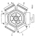
- blow molding machine attachment 32 Attached to the rear of the base 30 of the machine 10 is a blow molding machine attachment 32 which includes, in addition to the robot assembly 22, a six position horizontal rotatable table 34, with parison carrying pallets 36 mounted at each of six equispaced positions.
- An electric servo driven clamp 38 is mounted at one of the positions for stretch blow molding parisons.
- the rotary table 34 includes a loading station 42 at which the robot 22 loads batches of parisons 20 onto the individual pallets 36. As shown in this figure, two of the positions preceding the blow molding station 38 are occupied by thermal conditioning stations 40a and 40b. The conditioning stations 40a and 40b are used to adjust the thermal profile of the parisons where necessary. The position immediately following the blow molding station 38 is an open station that is followed by a stripper station 44 for removing the blown articles from the pallets 36. FIG. 2 schematically illustrates the relative positions of these stations.
- each of the pallets 36 is shown without parisons 20 or blown articles situated thereon.
- each pallet 36 would be loaded with parisons 20 or blown articles. More particularly, parisons 20 would be on or being transferred onto a pallet 36 at the robot station 22 and parisons 20 would be positioned on the pallets 36 at the two conditioning stations 40a and 40b and in the blow molding station 32. Blown articles would be positioned on the pallets 36 at the idle station and eject station 44.
- the rotation of the table 34 is indexed from station to station so as to optimize the production efficiency of both the injection molding and stretch blow molding processes, for given cavitation combinations of injection molds and blow molds.
- the table 34 may be rotated by a direct frameless servo electric drive, servo driven belt drive or any other known drive means 46 (see Fig. 4) of sufficient speed and positional accuracy.
- FIG. 3 shows a pallet 36 adjacent a conditioning station 40a.
- the thermal conditioning stations 40a and 40b are movable transversely and vertically in a manner well known to those skilled in the art. This enables the thermal conditioning to be tailored to the requirements of the particular parisons being processed.
- a system controller 50 provides control signals to the components of the injection stretch blow molding system in a preprogrammed timed sequence.
- the controller 50 also provides status information to a touch screen display panel 52 that enables an operator to intervene in the operation of the system as required.
- the operator control aspect of the system will not be described as it is unrelated to the operation of the present invention.
- the factor that limits the productivity of the injection blow molding system is the length of the injection cycle needed to form the parisons 20.
- the injection cycle takes about twelve seconds to create and deliver parisons 20 to the table 36.
- the blow-molding machine can blow the parisons 20 into blown articles in 3.5 seconds. Consequently, it is desirable to enable the blow-molding machine to perform at least two blow mold cycles for every injection molding cycle. In the present embodiment, this is achieved by providing twice as many injection cavities in the injection unit as there are blow mold cavities in the blow-molding machine. This requires that the injection unit provide two groups of parisons to the table 34 for each injection cycle in order to enable the blow molding machine to perform two blow molding cycles while the injection unit is performing a single injection cycle.
- parisons 20 are transferred to the table 36 at a regular interval, it is obvious that each set of parisons would be on the transfer table and at different stations around the table for different intervals of time. In many cases, this would lead to unsatisfactory blown articles because the parisons would arrive at the blow-molding machine 32 with different characteristics.
- the present invention enables the parisons 20 to arrive at the blow-molding machine 32 in sufficiently similar condition so that a uniform blown article can be obtained from each parison 20.
- the controller 50 provides operational signals to a blow mold control device 54, an injection mold control device 56, a thermal conditioning unit control device 58, a robot control device 60, an index motor control device 64 and a blown article ejection device 62.
- the signals may be from an analog or digital controller.
- a digital controller is preferred.
- the blow mold control device 54 receives signals from the controller 50 that enable it to control the opening, closing, clamping and blowing of parisons 20 in the blow molding machine 32 at the desired times during the processing cycle.
- the injection mold control device 56 receives signals from the controller 50 that enable it to control the opening, closing, clamping, injection and turret rotation of the injection molding machine 10.
- the thermal conditioning control device 58 receives signals from the controller 50 that enable the device 58 to move the thermal conditioning units 40a and 40b into or out of operative association with the parisons 20 on a pallet 36.
- the control device 58 also receives signals enabling it to raise or lower the thermal conditioning units 40a and 40b to enable the unit to condition the desired portion or portions of the parisons 20.
- the index motor control device 64 receives signals from the controller 50 that enable it to control the drive motor 46 to thereby rotate the table 34 at the appropriate times during the processing cycle.
- the article ejection control device 62 receives signals from the controller 50 enabling it to eject blown articles from the table 34 when the blown articles reach the ejection station 44.
- the reference to synchronous and asynchronous mode refers to the table indexing operation.
- the table 34 In the synchronous mode, the table 34 is indexed at regular intervals. In the asynchronous mode, the table 34 is indexed at differing intervals.
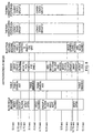
- Fig. 5 shows a typical cycle time diagram when the machine is being operated in the synchronous mode.
- the complete injection molding cycle takes 12 seconds whereas a blow molding cycle can be completed in 3.5 seconds.
- two groups of parisons 20 can be blow molded while the injection-molding machine 10 is performing a single injection cycle.
- two sets of parisons 20 are formed in the injection unit 10 during each injection cycle. This requires that the two groups of parisons 20 be dropped onto separate pallets 36 at different times so that the pallets 36 can be fed into the blow-molding machine 32 in sequence.
- the table 34 is indexed so that a first empty pallet 36 is disposed under a first row of tubes 26 holding parisons 20.
- the first group of parisons 20 is then dropped into the empty pallet 36.
- the table 34 is then indexed to bring the next empty pallet 36 into position under the arm of the robot 22.
- the arm of the robot 22 is moved laterally to move the second group of pallets 20 into position over the newly indexed empty pallet 36.
- the twelve-second-cycle time has been subdivided into quarter second intervals.
- the activity performed by the indexed system shown in Fig. 1 during each of these quarter-second intervals is identified by the legend on the left side of Fig. 5.
- the first three lines on the diagram illustrate the activity of the injection-molding machine (IMM) 10.
- the next seven lines indicate the activity performed by the robot 22.
- the next two lines indicate the activity at conditioning stations 40a and 40b.
- the last four lines indicate the operation of the blow molding machine (BMM) 32 in cooperation with the table indexing apparatus 46.
- BMM blow molding machine
- the injection molding process is indicated as initiated at the beginning of the cycle and not completed until ten seconds of the cycle has transpired.
- parison ejectors are moved into position to transfer parisons 20 on the mold core 14 to the tooling plate 24 on the robot 22 that has been rotated into its pick position during the interval between 1 and 2 seconds as shown at line three for the robot 22.
- This transfer procedure is well known in the art and will not be further described herein. This cycle is repeated every twelve seconds.
- robot 22 is in position to drop a second group of parisons 20 onto mandrels 52 (see Fig. 3) on a pallet 36.
- the pivoting head 28 is rotated ninety degrees so as to place the parisons 20 in a vertical position.
- the robot 22 is then positioned so that the plate 24 is properly aligned with a pallet 36.
- two sets of photo eyes are used to align the plate 24.
- the first photo eye aligns the first group of parisons 20 with the pallet 36 as indicated at line six for the robot 22. When the photo eye detects alignment, the first group of parisons 20 is dropped onto a pallet 36.
- the table is indexed a single position to bring another empty pallet 36 into position under the pivoting head 28.
- the tooling plates 24 are repositioned into alignment with the second photo eye and the second group of parisons are immediately dropped onto a pallet 36.
- the two groups of parisons 20 are now in position to be indexed around the rotatable table to the blow-molding machine 32.
- the 2.0 second dwell may be with the mold open, or closed with high air pressure. The dwell may be operator selected for either open or closed.
- FIG. 6 illustrates the sequence of operations that occur in the blow molding machine 32, conditioning stations 40a and 40b, transfer station 42 and the injection molding station 10 during a single twelve second injection molding cycle in the injection molding unit 10.
- the blow mold clamp 38 on the blow molding machine 32 is closed, a second group of parisons 20 from a previous injection cycle of the injection unit 10 is transferred to mandrels 52 on a pallet 36 at the transfer station 42, a second group of parisons 20 from an injection cycle prior to the previous injection cycle is held in the second conditioning station 40b and a first group of parisons 20 from the previous injection cycle is held in the first conditioning station 40a.
- the first group of parisons .20 from the injection cycle prior to the previous injection cycle are held within the blow mold clamp 38 and are blown into articles.
- the blow molding process can be completed in about 3.5 seconds, the blow mold is kept closed for about 5.5 seconds. As the table will not be indexed during this interval, the blow mold can remain closed without interfering with the operation of the table 34.
- the conditioning units 40a and 40b may remain active during the entire interval or any portion thereof or may be entirely inactive.
- the operation of the thermal conditioning units 40a and 40b is determined by the requirements of the particular parisons 20 being transported on the table 34.
- the blow mold clamp 38 is unclamped and opened about 5.5 seconds after it was clamped and closed.
- the table 34 can be indexed when the blow mold clamp 38 is open.
- the blow clamp 38 closes and clamps the blow mold to blow the second group of parisons from the injection cycle prior to the previous injection cycle into blown articles.
- the robot 22 remains in position to transfer the parisons 20 to a pallet 36 but does so as late in the index interval as possible. This enables the two groups of parisons 20 from the same injection cycle to be dropped onto a pallet 36 within a minimal time interval since the first group is dropped at the end of an index interval and the second group is dropped at the beginning of an index interval.
- both groups of parisons 20 are transferred to the table 34 within a minimal intervening interval.
- the first group of parisons 20 from an injection cycle remain at the transfer station 42 for about a second, at the first conditioning station 40a for about 5.5 seconds, at the second conditioning station 40b for about 5.5 seconds and the blow molding machine 32 for another 5.5 seconds.
- the second group of parisons 20 remains at the transfer station 42 for about five seconds and at each of the conditioning stations 40a and 40b and the blow molding station 32 for about six seconds.
- the first group When the table is indexed after receiving the first group of parisons 20, the first group is brought into position adjacent the first conditioning station 40a. In this operation, the first group of parisons 20 is dropped onto a pallet 36 and the table is immediately indexed to enable the second group of parisons 20 to be dropped onto a second pallet 36. The table is then only indexed after 4.5 seconds have elapsed. This means that the second group of parisons 20 remains in the transfer station 42 for 4.5 seconds longer than the first group of parisons 20. While the operation of the conditioning stations 40a and 40b can compensate for the difference in dwell time at the transfer station 42 for most parisons, it cannot do so for all types of parisons. Accordingly, some mechanism is required to ensure that each of the two groups of parisons 20 is treated equally. This can be achieved by indexing the table asynchronously which operation will be described hereinafter.
- the first group of parisons 20 is positioned adjacent the second conditioning station 40b and the second group of parisons 20 is positioned adjacent the first conditioning station 40a.
- each group of parisons is kept adjacent each conditioning station for the same interval of time so each parison 20 is conditioned in a like manner.
- the parisons 20 are fed into the blow molding station 32 and are blow molded into the desired article as quickly as is possible.
- the difference in the time at which the two groups of parisons 20 rest at the transfer station 42 is inconsequential as the time they are held at the conditioning stations 40a and 40b is sufficient to enable any differences in temperature conditioning to be temporized to the point that uniform articles can be blown from each group.
- the requirements to obtain a uniform product are so stringent that even this small variation in treatment of the two groups of parisons cannot be tolerated.
- the table 34 can be indexed asynchronously to ensure that each group of parisons is treated in a like manner. This asynchronous operation will be described hereinafter with reference to Fig.'s 7A to 7D and 8.
- the present invention provides a satisfactorily uniform blown article by indexing the transfer table 34 asynchronously to ensure that each group of parisons from a single set of parisons is treated substantially equally.
- the asynchronous movement of the table 34 enables the two groups of parisons 20 to be delivered to the transfer station 42 and the blow molding station 32 in rapid succession. The difference in time between delivering the two sets of parisons is only limited by how quickly the table 34 can be indexed.
- Figures 7A to 7D illustrate the treatment of two injection shots.
- each of the six pallets on the index table would be active so that three pallets would be carrying parisons, two pallets blown articles, and one pallet would be empty.
- Figures 7A to 7D illustrate the timing cycle for converting two injection shots from an injection unit 10 into blown articles.
- the overall cycle takes 48 seconds to complete, however, two groups of parisons and two groups of blown articles are produced every twelve seconds.
- the limiting factor on the output remains the length of time necessary to perform the injection operation since the blow molding operation can be completed in a much shorter time.
- the arm of the robot 22 is lined up so that the second group of parisons 20 from shot one can be dropped onto a pallet 36 as soon as the table 34 is indexed. In this way, both groups of parisons 20 from shot one are dropped onto the pallets 36 in quick succession.
- the first group of parisons 20 from shot 1 is conditioned at the first conditioning station 40a while the second group of parisons 20 from shot 1 is dropped onto a pallet 36.
- the arm of the robot 22 is rotated back into position to receive the two groups of parisons 20 from the second shot in the tooling plates 24.
- the parisons are not actually transferred to the tooling plates 24 at this time because they have not cooled sufficiently to be moved.
- the table 34 is again indexed.
- the first group of parisons 20 from shot one are indexed to the second conditioning station 40b and the second group of parisons 20 from shot one are indexed to the first conditioning station 40a.
- This interval lasts 7.5 seconds.
- the two groups of parisons 20 from shot 2 are cooled sufficiently to enable them to be transferred to the tooling plates 24.
- the tooling plates 24 receive the two groups of parisons 20 from shot two and the arm of robot 22 rotates ninety degrees.
- the arm of robot 22 is now positioned to drop the first group of parisons 20 from shot 2 onto a pallet 36 on the index table 34.
- the table 34 is indexed and the arm of the robot 22 moved to line up the second group of parisons 20 from the second shot with an incoming pallet 36 on the index table 34.
- This next interval lasts 3.5 seconds.
- the second group of parisons 20 from shot 2 is dropped onto a pallet 36 and the robot 22 is rotated ninety degrees back into a position where tooling plates 24 can receive parisons 20 from a third shot.
- the second group of parisons 20 from shot one are in the second conditioning station 40b and the first group of parisons 20 from shot two are at the first conditioning station 40a.
- the first group of parisons 20 from shot one is blown into the desired blown article in the blow-molding machine 32.
- the blow-molding machine clamp 38 is opened to enable the table 34 to be indexed.
- the next interval lasts 7.5 seconds.
- the blow mold clamp 38 is closed and the second group of parisons 20 from shot 1 are immediately blown.
- both groups of parisons 20 from the same shot are blown in quick succession so that there is little variance in their characteristics when the blow molding operation is performed.
- the first group of parisons 20 from shot 2 are in the second conditioning station 40b and the second group of parisons 20 from shot two are in the first conditioning station 40a.
- the first group of parisons from a third shot would be transferred to a pallet 36 now located under the robot 22.
- the handling of the third shot is not shown in Figures 7A to 7D. It is self-evident that each subsequent shot would be handled in like manner to the first two shots.
- the blow-molding machine After blowing the article, waits for the robot 22 and injection-molding machine 10 to be in condition to transfer the next set of parisons 20.
- the blow-mold is unclamped and opened to enable the table 34 to be indexed and the next interval started.
- This interval lasts 3.5 seconds and enables the second group of parisons 20 from shot two to complete its conditioning at the second conditioning station 40b. This ensures that each group of parisons 20 receives the same amount of conditioning time in the conditioning stations even though one group will spend more time in one conditioning station than the other.
- the first group of parisons 20 from shot two is blown and the blow mold 32 immediately opened to enable the table 34 to be indexed.
- the blow mold clamp 38 is closed and the second group of parisons 20 from the second shot is blow-molded into articles. Again, this enables the parisons 20 from both the first and second groups of shot two to be blow molded in quick succession and thereby obviate any problems that would arise if one group of parisons 20 was permitted to sit on the index table 34 for a longer period than the other group.
- This last interval of the cycle lasts for 7.5 seconds. It enables the injection molding unit 10 and robot 22 to get into position to transfer the next set of parisons 20 from the next shot. During the latter portion of this interval the blow-molding machine 32 is idle waiting for the robot 22 and injection molding unit 10 to perform their functions.
- FIG. 8 illustrates the blow-mold, conditioning and robot transfer sequence of operations as they occur when the stretch blow molding system is operated in asynchronous mode.
- FIG. 8 illustrates the sequence of operations that would occur during each twelve-second interval.
- the blow mold clamp 38 is closed and clamped and articles are blown in the blow molding machine 32 and the blow mold clamp 38 is reopened.
- a first group of parisons 20 is conditioned at conditioning station 40a and a second group of parisons 20 from an earlier injection cycle is conditioned at conditioning station 40b.
- a second group of parisons 20 is transferred from the arm of robot 22 to a pallet 36 at the transfer station 42.
- the table 34 is indexed so that each group of parisons 20 is moved up one stage on the table 34 and a first group of parisons 20 from a next injection cycle can be placed on the table 34.
- the blow mold clamp 38 is immediately closed and a second group of parisons 20 is blown into articles in the blow-molding machine 32.
- the blow mold clamp 38 remains closed until just before the table 34 is again ready to be indexed. Alternatively, the blow mold clamp 38 could be opened as soon as the blowing operation is complete.
- both groups of parisons 20 of a first injection cycle have been blown and both groups of parisons 20 of a second injection cycle are at one of the conditioning stations 40a or 40b.
- both groups of a third injection cycle are held in tubes 26 on the robot 22 in preparation for dropping onto pallets 36 on the table 34. Accordingly, this is the ideal time to delay indexing the table 34 since both groups of parisons 20 from each injection cycle are being treated in a like manner.
- the two groups from the first cycle have been blown into articles, the two groups from the second cycle are being thermally conditioned and the two groups from the third cycle are being held in the robot arm in preparation for transfer to the table.
- the blow mold clamp 38 is opened, the first group of parisons 20 from an injection cycle is placed on a pallet 36 at the transfer station 42 and the table 34 is then immediately indexed to initiate a shorter 3.5 second interval.
- the blow mold clamp 38 is immediately closed and a second group of parisons 20 from an injection cycle is immediately placed on a pallet 36 at the transfer station 42.
- a second group of parisons 20 is at the thermal conditioning station 40b and a first group of parisons 20 is at conditioning station 40a. In this way, each group of parisons 20 is conditioned for the same interval.
- the first group of parisons 20 of each injection cycle remains in conditioning station 40a for approximately 3.5 seconds and in conditioning station 40b for approximately 7.5 seconds.
- the second group of parisons 20 from each injection cycle remains in conditioning station 40b for approximately 3.5 seconds and in conditioning station 40a for approximately 7.5 seconds.
- each group of parisons 20 is in one or the other conditioning station for a total time of approximately 11 seconds of the twelve-second cycle.
- each group of parisons 20 is placed on the table 34 within an interval that is less than a second.
- the first group of parisons 20 of an injection cycle is transferred to the table 34 immediately prior to indexing of the table 34 and the second group of parisons 20 of the same injection cycle is transferred immediately after the table 34 has been indexed.
- the parisons 20 of a first group of an injection cycle are blown immediately before indexing of the table 34 and a second group of parisons 20 from the same injection cycle are blown immediately after indexing of the table 34. In this way, the interval between blowing of the first and second groups of parisons 20 from a particular injection cycle is reduced to a minimum.
Landscapes
- Engineering & Computer Science (AREA)
- Manufacturing & Machinery (AREA)
- Mechanical Engineering (AREA)
- Blow-Moulding Or Thermoforming Of Plastics Or The Like (AREA)
- Processing And Handling Of Plastics And Other Materials For Molding In General (AREA)
Claims (10)
- Vorrichtung zum Überführen von Vorformlingen (20) aus einer Spritzgießmaschine zu einer Blasformungsmaschine (32), wobei die Vorrichtung aufweist:einen Fortschalttisch (34) zum Bewegen einer Vielzahl von die Vorformlinge aufnehmenden Paletten (36) durch eine Vielzahl von Stationen, wobei die Stationen eine Vorformling-Aufnahmestation (42) und eine Blasformungsstation (38) umfassen, wobei die Paletten (36) sequentiell von Station zu Station schrittweise bewegt werden, wobei jede Palette (36) an jeder Station während einer vorbestimmten Zeitspanne stoppt, und jede dieser Paletten (36) eine Gruppe von Vorformlingen (20) an der Aufnahmestation (42) aufnimmt;Mittel zum Bereitstellen zumindest zwei dieser Gruppen von Vorformlingen (20) an der Aufnahmestation (42) während jedes Einspritzzyklus der Spritzgießmaschine (10);Mittel zum Fortschalten des Tisches (34) zum Bewegen der Paletten (36) von Station zu Station;wobei die Vorrichtung gekennzeichnet ist durch:Mittel zum Überführen einer ersten Gruppe von Vorformlingen (20) auf eine Palette (36) während zumindest eines Teiles der Zeitspanne und zum Überführen einer zweiten Gruppe von Vorformlingen (20) auf eine Platte (36) während eines ersten Teiles der Zeitspanne, welche auf die vorherige Zeitspanne folgt; undBlasen einer ersten Gruppe von Vorformlingen (20) in der Blasformungsstation (38) zu geblasenen Gegenständen während zumindest eines Teiles der Zeitspanne sowie Blasen einer zweiten Gruppe von Vorformlingen (20) zu geblasenen Gegenständen während eines ersten Teiles der Zeitspanne, die auf die vorhergehende Zeitspanne folgt.
- Vorrichtung nach Anspruch 1, bei welcher die Zeitspannen gleiche Längen haben und nicht länger als eine Hälfte der Zykluszeit der Spritzgießmaschine (10) sind.
- Vorrichtung nach Anspruch 1, bei welcher die Zeitspanne zum Überführen der ersten Gruppe von Vorformlingen (20) kürzer als die Zeitspanne zum Überführen der zweiten Gruppe von Vorformlingen (20) ist.
- Vorrichtung nach Anspruch 3, bei welcher die Zeitspanne zum Blasen der ersten Gruppe von Vorformlingen (20) durch die Blaszykluszeit der Blasformungsstation (38) bestimmt ist.
- Vorrichtung nach Anspruch 1, 3 oder 4, bei welcher zwei aufeinanderfolgende Zeitspannen im wesentlichen gleich der Zykluszeit der Spritzgießmaschine sind.
- Vorformling-Überführverfahren in einem Spritzgieß-Streckblassystem mit einer Spritzgießeinheit (10) zum gleichzeitigen Spritzgießen einer Vielzahl von Gruppen von Vorformlingen (20), Überführmitteln (22) zum Überführen der Vorformlinge (20) auf einen Fortschalttisch (34) Gruppe für Gruppe, wobei der Fortschalttisch zum Transportieren der überführten Gruppe von Vorformlingen (20) durch eine Vielzahl von Stationen und eine Blasformungsmaschine (32) an einer dieser Stationen (38) dient, wobei die Blasformungsmaschine (32) gleichzeitig eine einzelne Gruppe der Vorformlinge (20) zu geblasenen Gegenständen bläst, wobei der Tisch (34) zu vorbestimmten Zeitpunkten fortgeschaltet wird und zwischen den vorbestimmten Zeitpunkten stationär bleibt, wobei das Verfahren die Schritte umfaßt:Überführen einer ersten Gruppe von Vorformlingen (20) aus einem ersten Spritzgießzyklus auf den Tisch (34) unmittelbar vor dem Fortschalten des Tisches (34);Blasformen in der Blasformungsmaschine (32) einer ersten Gruppe von Vorformlingen (20) aus einem anderen Spritzgießzyklus zu blasgeformten Gegenständen unmittelbar vor dem Fortschalten des Tisches (34);Überführen einer zweiten Gruppe von Vorformlingen (20) von dem ersten Spritzgießzyklus auf den Tisch (34) unmittelbar nach dem Fortschalten des Tisches (34); undBlasformen in der Blasformungsmaschine (32) einer zweiten Gruppe von Vorformlingen (20) aus dem anderen Spritzgießzyklus zu blasgeformten Gegenständen unmittelbar nach dem Fortschalten des Tisches (34).
- Überführverfahren nach Anspruch 6, bei welchem die Zeitintervalle zwischen dem vorbestimmten Zeiten im wesentlichen gleich sind.
- Überführverfahren nach Anspruch 6, bei welchem die Zeitintervalle zwischen den vorbestimmten Zeiten ungleich groß sind.
- Überführverfahren nach Anspruch 7, bei welchem das Intervall etwa eine Hälfte der Spritzgießzykluszeit der Spritzgießeinheit (10) beträgt.
- Überführverfahren nach Anspruch 8, bei welchem die erste Zeitspanne im wesentlichen gleich der Zykluszeit der Blasformungsmaschine (32) ist, und eine kombinierte Zeit aus der ersten Zeitspanne und einer unmittelbar nachfolgenden Zeitspanne im wesentlichen gleich einer Spritzgießzykluszeit der Spritzgießeinheit (10) ist.
Applications Claiming Priority (3)
| Application Number | Priority Date | Filing Date | Title |
|---|---|---|---|
| US09/982,994 US6730260B2 (en) | 2001-10-22 | 2001-10-22 | Parts transfer method and apparatus for an injection stretch blow molding system |
| US982994 | 2001-10-22 | ||
| PCT/CA2002/001263 WO2003035369A1 (en) | 2001-10-22 | 2002-08-15 | Parts transfer method and apparatus for an injection stretch blow molding system |
Publications (2)
| Publication Number | Publication Date |
|---|---|
| EP1441896A1 EP1441896A1 (de) | 2004-08-04 |
| EP1441896B1 true EP1441896B1 (de) | 2007-11-07 |
Family
ID=25529720
Family Applications (1)
| Application Number | Title | Priority Date | Filing Date |
|---|---|---|---|
| EP02754040A Expired - Lifetime EP1441896B1 (de) | 2001-10-22 | 2002-08-15 | Verfahren und vorrichtung zum transportieren von vorformlingen aus einer spritzgiess-einheit zu einer streckblasvorrichtung |
Country Status (9)
| Country | Link |
|---|---|
| US (1) | US6730260B2 (de) |
| EP (1) | EP1441896B1 (de) |
| JP (1) | JP4388809B2 (de) |
| CN (1) | CN1299890C (de) |
| AT (1) | ATE377499T1 (de) |
| CA (1) | CA2458641C (de) |
| DE (1) | DE60223397D1 (de) |
| TW (1) | TW539604B (de) |
| WO (1) | WO2003035369A1 (de) |
Families Citing this family (16)
| Publication number | Priority date | Publication date | Assignee | Title |
|---|---|---|---|---|
| US8000837B2 (en) | 2004-10-05 | 2011-08-16 | J&L Group International, Llc | Programmable load forming system, components thereof, and methods of use |
| US20070042074A1 (en) * | 2005-08-19 | 2007-02-22 | Husky Injection Molding Systems Ltd. | Apparatus & molding system for rotating molded articles |
| US20090011157A1 (en) * | 2007-07-05 | 2009-01-08 | Husky Injection Molding Systems Ltd. | Molded Article, A Mold Insert for Producing the Molded Article and a Method of Manufacturing of the Mold Insert |
| US7976754B2 (en) * | 2007-08-29 | 2011-07-12 | Inergy Automotive Systems Research (S.A.) | Process for manufacturing a plastic hollow body, device and equipment for the implementation thereof |
| US20090211738A1 (en) * | 2008-02-22 | 2009-08-27 | Dennis Edwin Neal | System and Method for Continuous Rapid Cooling of Molten Materials to Produce Uniformly-Shaped Solid Forms |
| DE102010029644A1 (de) * | 2010-06-02 | 2011-12-08 | Krones Ag | Vorrichtung und Verfahren zum Herstellen von Kunststoffbehältern |
| EP2633976B1 (de) | 2010-10-25 | 2019-07-10 | Nissei Asb Machine Co., Ltd. | Vorrichtung zur spritzstreckblasformung |
| CN102358025B (zh) * | 2011-09-07 | 2014-04-16 | 铨宝工业股份有限公司 | 一种吹塑成形机及其分流方法 |
| DE102012005975A1 (de) * | 2012-03-23 | 2013-09-26 | Kraussmaffei Technologies Gmbh | Vorrichtung zum Bedienen einer mit einem Handhabungsgerät ausgestatteten Maschine |
| TWI488728B (zh) * | 2012-06-12 | 2015-06-21 | Chum Power Machinery Corp | 吹塑灌注設備配置系統及其運作方法 |
| DE102013004408A1 (de) | 2013-03-01 | 2014-09-04 | Otto Männer Innovation GmbH | Vorrichtung und Verfahren zum Spritzgießen und Kühlen von PET-Vorformlingen |
| CN103230104A (zh) * | 2013-04-23 | 2013-08-07 | 上海智联精工机械有限公司 | 在线定型输送机构及其定型输送工序 |
| US20150258721A1 (en) * | 2014-03-13 | 2015-09-17 | iMFLUX Inc. | Plastic Article Forming Apparatuses and Methods for Using the Same |
| EP3169507B1 (de) * | 2014-07-17 | 2025-01-08 | Sacmi Imola S.C. | Vorrichtung zum entladen und lagern von vorformen für die herstellung von kunststoffbehältern |
| CN104494114B (zh) * | 2014-12-19 | 2016-09-28 | 东莞市百纳通用机械有限公司 | 一种注吹模具 |
| DE102024101051A1 (de) | 2024-01-15 | 2025-07-17 | Krones Aktiengesellschaft | Vorrichtung und Verfahren zum Herstellen von Kunststoffbehältnissen mit Inspektion von Kunststoffvorformlingen |
Family Cites Families (19)
| Publication number | Priority date | Publication date | Assignee | Title |
|---|---|---|---|---|
| US4140464A (en) * | 1977-06-13 | 1979-02-20 | Emhart Industries, Inc. | Machine system for formation of molecularly oriented plastic bottles |
| US4310282A (en) * | 1977-06-13 | 1982-01-12 | Emhart Industries, Inc. | Delay stretch and blow machine system |
| DE2917055C2 (de) * | 1979-04-27 | 1981-12-17 | Voith Fischer Kunststofftechnik Gmbh U. Co Kg, 5204 Lohmar | Vorrichtung zum Spritzstreckblasformen biaxial orientierter Hohlkörper aus einem thermoplastischen Kunststoff |
| US4372910A (en) * | 1980-06-23 | 1983-02-08 | Van Dorn Company | Method for molding hollow plastic articles |
| US4793960A (en) * | 1985-05-14 | 1988-12-27 | Husky Injection Molding Systems Ltd. | Process for preparing hollow plastic articles |
| US4824359A (en) * | 1986-12-15 | 1989-04-25 | Hoover Universal, Inc. | Dual injection mold preform transfer assembly |
| IT1222066B (it) | 1987-07-20 | 1990-08-31 | Ferruccio Giacobbe | Apparecchiatura compatta per la formazione di contenitori cavi in materiale plastico molecolarmente orientabile |
| CN1028081C (zh) * | 1988-07-13 | 1995-04-05 | 日精A·S·B精机械株式会社 | 型坯的传送装置 |
| JPH0647272B2 (ja) * | 1989-11-17 | 1994-06-22 | 日精エー・エス・ビー機械株式会社 | 射出延伸吹込成形方法 |
| US5468443A (en) * | 1992-04-24 | 1995-11-21 | Nissei Asb Machine Co., Ltd. | Method and apparatus of injection stretch blow molding |
| JP3130140B2 (ja) * | 1992-08-31 | 2001-01-31 | 日精エー・エス・ビー機械株式会社 | 射出延伸吹込成形方法及び装置 |
| US5403177A (en) * | 1993-07-16 | 1995-04-04 | Jomar Corporation | Injection stretch blow molding machine |
| TW508300B (en) * | 1994-09-16 | 2002-11-01 | Asb Co Ltd | Injection-stretch-blow moulding method |
| US5607706A (en) * | 1995-04-05 | 1997-03-04 | Husky Injection Molding Systems Ltd. | Preconditioning preforms on a reheat blow molding system |
| JP3824360B2 (ja) * | 1996-10-09 | 2006-09-20 | 日精エー・エス・ビー機械株式会社 | 射出延伸ブロー成形装置及び成形方法 |
| IT1294138B1 (it) * | 1997-07-03 | 1999-03-22 | Sipa Spa | Procedimento ed apparato monostadio ad alta produttivita' per la produzione di contenitori in resina termoplastica |
| JP2002521236A (ja) * | 1998-07-31 | 2002-07-16 | ハスキー インジェクション モールディング システムズ インコーポレイテッド | 小型の成形後冷却装置 |
| DE19843053A1 (de) | 1998-09-19 | 2000-03-23 | Krupp Corpoplast Masch | Verfahren und Vorrichtung zur Steuerung eines Blasvorganges |
| US6146134A (en) * | 1999-05-20 | 2000-11-14 | Husky Injection Molding Systems Ltd. | Oven-pallet alignment and profiled heating of preforms |
-
2001
- 2001-10-22 US US09/982,994 patent/US6730260B2/en not_active Expired - Fee Related
-
2002
- 2002-08-15 EP EP02754040A patent/EP1441896B1/de not_active Expired - Lifetime
- 2002-08-15 AT AT02754040T patent/ATE377499T1/de not_active IP Right Cessation
- 2002-08-15 JP JP2003537909A patent/JP4388809B2/ja not_active Expired - Fee Related
- 2002-08-15 WO PCT/CA2002/001263 patent/WO2003035369A1/en not_active Ceased
- 2002-08-15 CA CA002458641A patent/CA2458641C/en not_active Expired - Fee Related
- 2002-08-15 CN CNB028209729A patent/CN1299890C/zh not_active Expired - Fee Related
- 2002-08-15 DE DE60223397T patent/DE60223397D1/de not_active Expired - Lifetime
- 2002-08-27 TW TW091119389A patent/TW539604B/zh not_active IP Right Cessation
Also Published As
| Publication number | Publication date |
|---|---|
| CA2458641C (en) | 2006-10-24 |
| TW539604B (en) | 2003-07-01 |
| US6730260B2 (en) | 2004-05-04 |
| JP2005506224A (ja) | 2005-03-03 |
| US20030075838A1 (en) | 2003-04-24 |
| DE60223397D1 (de) | 2007-12-20 |
| EP1441896A1 (de) | 2004-08-04 |
| CA2458641A1 (en) | 2003-05-01 |
| ATE377499T1 (de) | 2007-11-15 |
| WO2003035369A1 (en) | 2003-05-01 |
| CN1299890C (zh) | 2007-02-14 |
| CN1575224A (zh) | 2005-02-02 |
| JP4388809B2 (ja) | 2009-12-24 |
Similar Documents
| Publication | Publication Date | Title |
|---|---|---|
| US6730260B2 (en) | Parts transfer method and apparatus for an injection stretch blow molding system | |
| EP1608496B1 (de) | Plattenmontierte vorrichtung zum kühlen nach dem formen | |
| US4140464A (en) | Machine system for formation of molecularly oriented plastic bottles | |
| US4382760A (en) | Apparatus for high rate production of biaxially oriented thermoplastic articles | |
| US4313720A (en) | Parison transfer means | |
| RU2294832C2 (ru) | Устройство и способ постформовочного охлаждения, предусматривающие поворот и поперечное перемещение | |
| US4140468A (en) | Plastic bottle forming machine with modular design | |
| EP0283644B2 (de) | Vorrichtung zum Herstellen von hohlen Artikeln aus Kunststoff | |
| US4432720A (en) | Apparatus for high rate production of biaxially oriented thermoplastic articles | |
| US4261949A (en) | Process for formation of molecularly oriented plastic bottles | |
| US6827571B2 (en) | Apparatus for injection-molding plastic material articles consisting of a plurality of components | |
| US7946836B2 (en) | Injection molding and temperature conditioning apparatus | |
| EP0585859B1 (de) | Verfahren und Vorrichtung zum Spritzstreckblasen | |
| CN100537191C (zh) | 塑料物品的模制 | |
| US4435146A (en) | Apparatus for high rate production of biaxially oriented thermoplastic articles | |
| US6217819B1 (en) | Universal single-row and multi-row insert stretch blow molding method and apparatus therefor | |
| JP2024051146A (ja) | 樹脂製容器の製造装置及び製造方法 | |
| EP0664741B1 (de) | Verfahren und vorrichtung zum übertragen von hohlen plastikgegenständen | |
| US6713013B2 (en) | Single-row and multi-row stretch blow molding method and apparatus therefor | |
| US4895509A (en) | Compact apparatus for molding hollow containers in molecularly orientatable plastic material | |
| KR101210160B1 (ko) | 플라스틱 물품의 성형 | |
| JP3522293B2 (ja) | 射出延伸吹込成形方法 | |
| JPH03159726A (ja) | 射出延伸吹込成形方法 | |
| EP4653351A1 (de) | Behältertransportvorrichtung, behältertransportverfahren und blasformvorrichtung | |
| JP2000318022A (ja) | 熱可塑性プラスチック成形品の製造方法及びこの方法を実施するための射出ブロー成形機 |
Legal Events
| Date | Code | Title | Description |
|---|---|---|---|
| PUAI | Public reference made under article 153(3) epc to a published international application that has entered the european phase |
Free format text: ORIGINAL CODE: 0009012 |
|
| 17P | Request for examination filed |
Effective date: 20040524 |
|
| AK | Designated contracting states |
Kind code of ref document: A1 Designated state(s): AT BE BG CH CY CZ DE DK EE ES FI FR GB GR IE IT LI LU MC NL PT SE SK TR |
|
| AX | Request for extension of the european patent |
Extension state: AL LT LV MK RO SI |
|
| RIN1 | Information on inventor provided before grant (corrected) |
Inventor name: MASON, STEPHEN, J. Inventor name: VARDIN, CHRISTIAN, N. |
|
| 17Q | First examination report despatched |
Effective date: 20060919 |
|
| GRAP | Despatch of communication of intention to grant a patent |
Free format text: ORIGINAL CODE: EPIDOSNIGR1 |
|
| GRAS | Grant fee paid |
Free format text: ORIGINAL CODE: EPIDOSNIGR3 |
|
| GRAA | (expected) grant |
Free format text: ORIGINAL CODE: 0009210 |
|
| AK | Designated contracting states |
Kind code of ref document: B1 Designated state(s): AT BE BG CH CY CZ DE DK EE ES FI FR GB GR IE IT LI LU MC NL PT SE SK TR |
|
| REG | Reference to a national code |
Ref country code: GB Ref legal event code: FG4D |
|
| REG | Reference to a national code |
Ref country code: IE Ref legal event code: FG4D |
|
| REG | Reference to a national code |
Ref country code: CH Ref legal event code: EP |
|
| REF | Corresponds to: |
Ref document number: 60223397 Country of ref document: DE Date of ref document: 20071220 Kind code of ref document: P |
|
| PG25 | Lapsed in a contracting state [announced via postgrant information from national office to epo] |
Ref country code: LI Free format text: LAPSE BECAUSE OF FAILURE TO SUBMIT A TRANSLATION OF THE DESCRIPTION OR TO PAY THE FEE WITHIN THE PRESCRIBED TIME-LIMIT Effective date: 20071107 Ref country code: CH Free format text: LAPSE BECAUSE OF FAILURE TO SUBMIT A TRANSLATION OF THE DESCRIPTION OR TO PAY THE FEE WITHIN THE PRESCRIBED TIME-LIMIT Effective date: 20071107 Ref country code: NL Free format text: LAPSE BECAUSE OF FAILURE TO SUBMIT A TRANSLATION OF THE DESCRIPTION OR TO PAY THE FEE WITHIN THE PRESCRIBED TIME-LIMIT Effective date: 20071107 Ref country code: ES Free format text: LAPSE BECAUSE OF FAILURE TO SUBMIT A TRANSLATION OF THE DESCRIPTION OR TO PAY THE FEE WITHIN THE PRESCRIBED TIME-LIMIT Effective date: 20080218 Ref country code: SE Free format text: LAPSE BECAUSE OF FAILURE TO SUBMIT A TRANSLATION OF THE DESCRIPTION OR TO PAY THE FEE WITHIN THE PRESCRIBED TIME-LIMIT Effective date: 20080207 |
|
| NLV1 | Nl: lapsed or annulled due to failure to fulfill the requirements of art. 29p and 29m of the patents act | ||
| PG25 | Lapsed in a contracting state [announced via postgrant information from national office to epo] |
Ref country code: BG Free format text: LAPSE BECAUSE OF FAILURE TO SUBMIT A TRANSLATION OF THE DESCRIPTION OR TO PAY THE FEE WITHIN THE PRESCRIBED TIME-LIMIT Effective date: 20080207 |
|
| REG | Reference to a national code |
Ref country code: CH Ref legal event code: PL |
|
| PG25 | Lapsed in a contracting state [announced via postgrant information from national office to epo] |
Ref country code: AT Free format text: LAPSE BECAUSE OF FAILURE TO SUBMIT A TRANSLATION OF THE DESCRIPTION OR TO PAY THE FEE WITHIN THE PRESCRIBED TIME-LIMIT Effective date: 20071107 |
|
| PG25 | Lapsed in a contracting state [announced via postgrant information from national office to epo] |
Ref country code: CZ Free format text: LAPSE BECAUSE OF FAILURE TO SUBMIT A TRANSLATION OF THE DESCRIPTION OR TO PAY THE FEE WITHIN THE PRESCRIBED TIME-LIMIT Effective date: 20071107 Ref country code: DK Free format text: LAPSE BECAUSE OF FAILURE TO SUBMIT A TRANSLATION OF THE DESCRIPTION OR TO PAY THE FEE WITHIN THE PRESCRIBED TIME-LIMIT Effective date: 20071107 |
|
| EN | Fr: translation not filed | ||
| PG25 | Lapsed in a contracting state [announced via postgrant information from national office to epo] |
Ref country code: SK Free format text: LAPSE BECAUSE OF FAILURE TO SUBMIT A TRANSLATION OF THE DESCRIPTION OR TO PAY THE FEE WITHIN THE PRESCRIBED TIME-LIMIT Effective date: 20071107 Ref country code: BE Free format text: LAPSE BECAUSE OF FAILURE TO SUBMIT A TRANSLATION OF THE DESCRIPTION OR TO PAY THE FEE WITHIN THE PRESCRIBED TIME-LIMIT Effective date: 20071107 |
|
| PLBE | No opposition filed within time limit |
Free format text: ORIGINAL CODE: 0009261 |
|
| STAA | Information on the status of an ep patent application or granted ep patent |
Free format text: STATUS: NO OPPOSITION FILED WITHIN TIME LIMIT |
|
| PG25 | Lapsed in a contracting state [announced via postgrant information from national office to epo] |
Ref country code: PT Free format text: LAPSE BECAUSE OF FAILURE TO SUBMIT A TRANSLATION OF THE DESCRIPTION OR TO PAY THE FEE WITHIN THE PRESCRIBED TIME-LIMIT Effective date: 20080407 |
|
| 26N | No opposition filed |
Effective date: 20080808 |
|
| PG25 | Lapsed in a contracting state [announced via postgrant information from national office to epo] |
Ref country code: DE Free format text: LAPSE BECAUSE OF FAILURE TO SUBMIT A TRANSLATION OF THE DESCRIPTION OR TO PAY THE FEE WITHIN THE PRESCRIBED TIME-LIMIT Effective date: 20080208 Ref country code: FR Free format text: LAPSE BECAUSE OF FAILURE TO SUBMIT A TRANSLATION OF THE DESCRIPTION OR TO PAY THE FEE WITHIN THE PRESCRIBED TIME-LIMIT Effective date: 20080822 |
|
| PG25 | Lapsed in a contracting state [announced via postgrant information from national office to epo] |
Ref country code: GR Free format text: LAPSE BECAUSE OF FAILURE TO SUBMIT A TRANSLATION OF THE DESCRIPTION OR TO PAY THE FEE WITHIN THE PRESCRIBED TIME-LIMIT Effective date: 20080208 |
|
| PG25 | Lapsed in a contracting state [announced via postgrant information from national office to epo] |
Ref country code: FI Free format text: LAPSE BECAUSE OF FAILURE TO SUBMIT A TRANSLATION OF THE DESCRIPTION OR TO PAY THE FEE WITHIN THE PRESCRIBED TIME-LIMIT Effective date: 20071107 |
|
| PG25 | Lapsed in a contracting state [announced via postgrant information from national office to epo] |
Ref country code: MC Free format text: LAPSE BECAUSE OF NON-PAYMENT OF DUE FEES Effective date: 20080831 |
|
| GBPC | Gb: european patent ceased through non-payment of renewal fee |
Effective date: 20080815 |
|
| PG25 | Lapsed in a contracting state [announced via postgrant information from national office to epo] |
Ref country code: EE Free format text: LAPSE BECAUSE OF FAILURE TO SUBMIT A TRANSLATION OF THE DESCRIPTION OR TO PAY THE FEE WITHIN THE PRESCRIBED TIME-LIMIT Effective date: 20071107 |
|
| PG25 | Lapsed in a contracting state [announced via postgrant information from national office to epo] |
Ref country code: CY Free format text: LAPSE BECAUSE OF FAILURE TO SUBMIT A TRANSLATION OF THE DESCRIPTION OR TO PAY THE FEE WITHIN THE PRESCRIBED TIME-LIMIT Effective date: 20071107 Ref country code: IE Free format text: LAPSE BECAUSE OF NON-PAYMENT OF DUE FEES Effective date: 20080815 |
|
| PG25 | Lapsed in a contracting state [announced via postgrant information from national office to epo] |
Ref country code: GB Free format text: LAPSE BECAUSE OF NON-PAYMENT OF DUE FEES Effective date: 20080815 |
|
| PG25 | Lapsed in a contracting state [announced via postgrant information from national office to epo] |
Ref country code: LU Free format text: LAPSE BECAUSE OF NON-PAYMENT OF DUE FEES Effective date: 20080815 |
|
| PG25 | Lapsed in a contracting state [announced via postgrant information from national office to epo] |
Ref country code: TR Free format text: LAPSE BECAUSE OF FAILURE TO SUBMIT A TRANSLATION OF THE DESCRIPTION OR TO PAY THE FEE WITHIN THE PRESCRIBED TIME-LIMIT Effective date: 20071107 |
|
| PG25 | Lapsed in a contracting state [announced via postgrant information from national office to epo] |
Ref country code: IT Free format text: LAPSE BECAUSE OF NON-PAYMENT OF DUE FEES Effective date: 20080831 |