EP1442935B1 - Compartiment à bagages installé au-dessus de la hauteur de la tête - Google Patents
Compartiment à bagages installé au-dessus de la hauteur de la tête Download PDFInfo
- Publication number
- EP1442935B1 EP1442935B1 EP03425062A EP03425062A EP1442935B1 EP 1442935 B1 EP1442935 B1 EP 1442935B1 EP 03425062 A EP03425062 A EP 03425062A EP 03425062 A EP03425062 A EP 03425062A EP 1442935 B1 EP1442935 B1 EP 1442935B1
- Authority
- EP
- European Patent Office
- Prior art keywords
- roof
- coupling
- overhead luggage
- bin structure
- wall
- Prior art date
- Legal status (The legal status is an assumption and is not a legal conclusion. Google has not performed a legal analysis and makes no representation as to the accuracy of the status listed.)
- Expired - Lifetime
Links
Images




Classifications
-
- B—PERFORMING OPERATIONS; TRANSPORTING
- B60—VEHICLES IN GENERAL
- B60R—VEHICLES, VEHICLE FITTINGS, OR VEHICLE PARTS, NOT OTHERWISE PROVIDED FOR
- B60R5/00—Compartments within vehicle body primarily intended or sufficiently spacious for trunks, suit-cases, or the like
- B60R5/003—Luggage racks, e.g. for busses
Definitions
- the present invention refers to an overhead luggage bin structure for locomotion means for transporting people, and in particular for buses.
- an overhead luggage bin structure is provided above each seat to hold luggage (see, for example, US 5 441 326).
- Said overhead luggage bin structure is generally disposed beneath the roof of the bus and alongside an aeration channel.
- Said air channel is defined near the meeting zone of the side wall and the roof of the bus and the air or conditioned air to be delivered to the passenger compartment of the bus passes there through.
- the overhead luggage bin structure defines the air channel and/or the proper overhead luggage bin, designed to hold the luggage.
- the term "overhead luggage bin” is intended to denote such a structure which may lack a proper bin and may be adapted only to define the air channel.
- overhead luggage bin structures currently comprise structural shapes which extend substantially for the entire length of the bus, connected by means of supporting brackets spaced apart from each other.
- the structural shapes and the brackets are fixed to the roof and to the side wall of the bus by means of bolts.
- both the structural shapes and the brackets of the overhead luggage bin structure must be designed so as to adapt to the shape of the roof and of the sidewall of the bus for which they are intended.
- An object of the present invention is to overcome the drawbacks of the prior art by providing an overhead luggage bin structure that is highly versatile and suitable to be employed in various types of locomotion means for transporting passengers.
- Another object of the present invention is to provide an overhead luggage bin structure which has a limited number of components and is inexpensive and easy to make.
- the overhead luggage bin structure for locomotion means for transporting passengers comprises a structural shape for coupling to the roof of the locomotion means and a structural shape for coupling to the wall of the locomotion means joined together by means of a plurality of brackets of the air channel, so as to define a channel for the passage of air near the joining edge between the roof and the wall.
- said overhead luggage bin structure comprises fixing means suitable to be fixed firmly to the roof and the side wall and to couple adjustably to the roof coupling structural shape and to the wall coupling structural shape.
- the roof coupling structural shape and the wall coupling structural shape can adapt to the particular shape of the roof and of the wall and to the angle of the roof with respect to the wall.
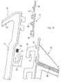
- a roof 1 of a bus and a side wall 2 of a bus joined by an angular edge 3 are illustrated in part.
- the plane of the roof 1 and the plane of the side wall 2 form an obtuse angle ⁇ which is slightly greater than 90°.
- the angle ⁇ varies according to the types and to the models of bus.
- the roof 1 also, which is shown rectilinear in the example, can take on a convex shape or other curvature, according to the model of bus.
- An overhead luggage bin structure denoted as a whole with reference numeral 4, comprises a structural shape 5 for coupling to the roof 1 and a structural shape 6 for coupling to the wall 2 joined together by means of a plurality of brackets 30.
- the structural shapes 5 and 6 for coupling to the roof and to the wall extend substantially for the entire length of the bus, whereas the brackets 30 are spaced apart from one another.
- the roof coupling structural shape 5 is fixed to the roof 1 by means of a roof coupling support 7 (visible in the Figure), in the form of an extruded structural shape which extends for the entire length of the bus.
- a plurality of supports 7 for coupling to the roof, spaced apart from each other along the entire length of the bus, can also be used.
- the support 7 for coupling to the roof is fixed to the underside of the roof 1 by means of bolts 8.
- the support 7 for coupling to the roof has a base portion 9 which abuts against the underside of the roof 1.
- One end of the base part 9 extends in a supporting part 10, rounded in shape and thicker, which protrudes downward from the base part.
- a cam seat 11 is provided, formed by a curved slot, substantially C-shaped when seen in cross section.
- the curved slot 11 defines an end 14 of the supporting part having a rounded profile.
- the roof coupling structural shape 5 comprises a flat rectangular plate 12, designed to be disposed along a substantially vertical plane, parallel to the side wall 2 of the bus.
- Said roof coupling structural shape 5 has a top end 13 having a curved shape, with a substantially C-shaped curve, complementary to the curved seat 11 of the roof coupling support.
- the end 13 of the roof coupling structural shape 5 can engage in the seats 11 of the roof coupling supports 10 and thus the curved end 13 of the roof coupling structural shape is supported, with the possibility of angular adjustment, on the rounded end 14 of the roof coupling supports.
- the roof coupling structural shape 12 [the plate 12 of the roof coupling structural shape 5; translator's note] can be turned around a longitudinal axis passing through the centre of curvature of its end 13, so as to adapt to the shape of the roof 1 and of the wall 2 of the bus, that is to say to the angle ⁇ defined between the roof 1 and the wall 2 of the bus, and to the curvature of the roof 1.
- each supporting rib 15 defines a coupling seat 16 having a U-shaped profile.
- four supporting ribs 15 placed equidistant in height from one another have been shown by way of example.
- a plurality of brackets 30 of the air channel disposed spaced apart from each other are fixed to the roof coupling structural shape 5.
- the bracket of the air channel 30 is shaped as a triangle with a right angle.
- the bracket 30 is defined by three sides, that is to say a vertical cathetus 31, a horizontal cathetus 32 and a hypotenuse 33.
- Two downward facing, outward protruding coupling teeth 34 are provided on the vertical cathetus 31, near the top end thereof. Each tooth 34 has a slot 35. Again on the vertical cathetus 31, near the bottom end thereof, two hooks 36 which protrude outward and upward and have an inverted L-shape to define respective coupling seats 37 are provided.
- a downward facing coupling seat 38 defined by a substantially inverted U-shaped profile, is provided in the horizontal cathetus 32 near the vertical cathetus 31.
- An outward protruding coupling tooth 39 is provided at the end of the horizontal cathetus 31 facing towards the hypotenuse 33.
- the bracket 30 is coupled to the roof coupling structural shape 5, inserting the top teeth 34 of the bracket into the seats 16 of the structural shape 5. Subsequently the bracket 30 is lowered so that the upward facing protrusions of the ribs 15 of the structural shape 5 engage in the slots 35 of the teeth 34 of the bracket. At this point, spacers 40 that block the bracket firmly are inserted longitudinally into gap remaining into the seats 16 of the structural shape 5. It should be noted that the position of each bracket 30 can be adjusted in height, according to the seats 16 occupied by the teeth 34, to allow the structure to be adapted to different angles of inclination thereof.
- a coupling seat 17 facing in the opposite direction to the wall 2 of the bus (toward the right with reference to the Figures) is provided.
- the coupling seat 17 is defined by a substantially C-shaped portion 18 of the plate 12.
- the top cover 19 has pins or clips 20 able to engage in the seats 17 of the roof coupling structural shape.
- Each clip 20 consists of two elastic tongues 21, separated from each other by a slot 22, so as to be able to bend elastically in said slot 22.
- protrusions 23, acting as shock-absorbers to abut against the plate 12 of the roof coupling structural shape, are provided in the side portion of the closing hood or cover 19.
- the hood 19 is disposed at a short distance from a plate-shaped structural shape 41 fixed to the underside of the roof 1. In this manner a channel 42 for the passage of air is defined between the structural shape 41 and the hood 19.
- slots 43 are provided at one end of the hood 19 for discharge of the air from the channel 42 into the passenger compartment of the bus.
- a seat able to receive a support 44 for the door is defined in the hood 19, near the air outlet end 43.
- a door 46 to close the overhead luggage bin structure is hinged to the support 44 by means of a pivot 45.
- the bottom end of the side part of the hood 19 is connected, by means of a upper connecting structural shape 47, to a base cover 48 of the overhead luggage bin, which forms the base on which the luggage is placed.
- the base cover 48 of the overhead luggage bin structure is supported by a plurality of brackets of the overhead luggage bin, arranged spaced out.
- the bracket 50 of the overhead luggage bin structure has an irregular substantially triangular shape, and has a bottom side 51, a top side 52 and a vertical side 53.
- the base cover 48 of the overhead luggage bin structure is supported in the top side 52.
- a first seat 54, near the vertical side 53, and a second seat 55 in a central position are formed in the bottom side 51.
- Two hooks 56 protruding outward and downward so as to define respective seats 57 are provided in the vertical side 53.
- the hooks 56 of the luggage bin bracket are of a shape substantially complementary to that of the hooks 36 of the air channel bracket.
- the hooks 56 of the luggage bin bracket engage in the slots 37 of the hooks of the air channel bracket and the hooks 36 of the air channel bracket engage reciprocally in the slots 57 of the hooks of the luggage bin bracket.
- a longitudinal spacer 58 is inserted between the hooks 36 and 56.
- the luggage bin brackets 50 and thus the base 48 of the overhead luggage bin structure are also adjusted in height, thus reducing or increasing the vertical distance between the base 48 of the overhead luggage bin structure and the upper part of the hood 19 as desired, with a consequent reduction or increase of the capacity of the luggage compartment.
- the upper connecting structural shape 47 has a substantially inverted C-shaped seat 60 in a central position which hooks onto a pin 61.
- the connecting structural shape 47 has at its top end a U-shaped seat 62 which receives the bottom end of the hood 19. Furthermore, the connecting structural shape 47 has at its bottom end an inverted U-shaped seat 63 which receives the top end of the bottom cover 48 of the overhead luggage bin.
- a substantially Greek fret-shaped structural shape 74 engages in the seat 38 of each air channel bracket.
- a spacer 75 is inserted in the seat 38 of the bracket 30 to fix the Greek fret-shaped structural shape 74.
- abutment structural shape 76 Fixed to the Greek fret-shaped structural shape is an abutment structural shape 76 which has a rounded abutment surface 77 that abuts against a rounded abutment surface 78 of another connecting structural shape 80 which is fixed to the bracket 50 of the overhead luggage bin.
- a spacer 81 is used to eliminate play between the bracket 50 of the overhead luggage bin structure and the structural shape 80 and also for mechanical fixing between the bracket 50 and the structural shape 80.
- the connecting structural shape 80 has a portion 82 shaped substantially as an inverted U which engages in the seat 54 of the bracket 50.
- the folded edge of a bottom cover 83 is fixed to the inverted U-shaped portion 82.
- the other edge of the bottom cover 83 is fixed to a T-shaped structural shape 84 disposed in the seats 55 of each bracket 50 of the overhead luggage bin.
- a handrail 85 in the form of a substantially tubular structural shape is mounted at the free end of each luggage bin bracket 50 and also forms an abutment ledge for the luggage if the door 46 is not provided. In any case the bottom end of the door 46 abuts against the handrail 85.
- An inverted U-shaped seat 86 is provided in the bottom part of the handrail 85.
- Another bottom cover 87 has an edge fixed to the T-shaped structural shape 84 and the other edge fixed in the slot 86 of the handrail 85.
- the multiset 88 can include adjustable lights, air outlet nozzles and the like.
- a third bottom cover 89 fixed to the Greek fret-shaped structural shape is directed toward the wall 2 of the bus, defining the bottom wall of the air channel. Said cover 89 is fixed to the wall connection structural shape 6.
- the multiset 88 has been shown mounted on the bottom cover 83 disposed beneath the base 48 of the overhead luggage bin, the multiset 88 could similarly be mounted on the bottom cover 89 which defines the air channel.
- the wall connection structural shape 6 comprises a flat, vertical rectangular plate 90 from which protrude horizontal ribs 91 facing in the opposite direction to the wall 2 of the bus.
- Each rib 91 ends in an upward facing retaining tooth 92 which defines a seat 93.
- Four ribs 91 spaced at an equal distance from each other are preferably provided for better adjustment.
- the seats 93 of the wall connection structural shape 6 are able to receive the coupling teeth 39 of the air channel brackets 30.
- a spacer 95 in the form of a plug is inserted.
- the height and inclination of the bracket 30 of the air channel can be adjusted, adapting it to the shape of the sidewall 2 and the roof 1 of the bus.
- a horizontal rib extends which ends in a substantially inverted U-shaped portion which defines a seat 96 able to receive the ends of one or more substantially L-shaped supports 97 fixed by means of bolts to the side wall 2 of the bus.
- the bottom end of the structural shape 6 is rounded and ends in a substantially inverted L-shaped seat able to receive the folded inverted U-shaped edge of the bottom cover 89.
- Figure 1 shows an overhead luggage bin structure 4 in its most complete form, able to support various optional elements of the overhead luggage bin, such as the base 48, the brackets 50, the bottom covers 83, 87 with the multiset 88, the handrail 85 and the door 46.
- FIG 8 shows an overhead luggage bin structure 4 in its simplest form, wherein the optional elements of the overhead luggage bin structure have been omitted and wherein like or similar elements to those already described are denoted by the same reference numerals and a detailed description thereof is omitted.
- the overhead luggage bin structure 4 comprises a side cover structural shape 100 which, together with the hood 19 and the bottom cover 89, defines the air channel.
- the side cover structural shape 100 has at its top end a U-shaped seat 102 able to receive the bottom end of the hood 19 and ribs 101 able to engage in the seats 37 of the hooks 36 of the air channel brackets 30 and a rounded bottom end 103 able to abut with the rounded abutment surface 77 ( Figure 5) of the abutment structural shape 76.
Landscapes
- Engineering & Computer Science (AREA)
- Mechanical Engineering (AREA)
- Vehicle Step Arrangements And Article Storage (AREA)
- Fittings On The Vehicle Exterior For Carrying Loads, And Devices For Holding Or Mounting Articles (AREA)
- Body Structure For Vehicles (AREA)
Claims (12)
- Structure suspendue de casier à bagages (4) pour moyen de locomotion pour le transport de passagers, comme des bus et similaires, comprenant une forme structurelle (5) à coupler au toit (1) et une forme structurelle (6) à coupler à une paroi latérale (2) du moyen de locomotion, connectées entre elles au moyen d'une pluralité de consoles (30) du canal à air de manière à définir, près du bord de jointure (3), entre le toit (1) et la paroi (2), un canal pour le passage de l'air,
caractérisée en ce que ladite structure suspendue de casier à bagages (4) comprend des moyens de fixation (7, 27) susceptibles d'être fixés solidement au toit (1) et à la paroi latérale (2) respectivement et de se coupler de manière ajustable à ladite forme structurelle (5) à coupler au toit (1) et à ladite forme structurelle (6) à coupler à la paroi latérale (2) afin de permettre à la forme structurelle (5) à coupler au toit et à la forme structurelle (6) à coupler à la paroi d'être adaptables à la forme du toit (1) et de la paroi (2) et à l'angle d'inclinaison (α) du toit (1) par rapport à la paroi (2). - Structure suspendue de casier à bagages selon la revendication 1, caractérisée en ce que ledit moyen de fixation au toit (1) comprend au moins un support (7) susceptible d'être fixé sur le dessous du toit (1) et présentant une fente incurvée (11) susceptible de recevoir l'extrémité supérieure incurvée (13) de ladite forme structurelle (5) couplée au toit, de sorte que ladite forme structurelle couplée au toit (5) peut tourner autour de l'axe traversant le centre d'incurvation de ladite fente incurvée (11) du support de fixation au toit (7) pour s'adapter audit angle d'inclinaison (α) du toit (1) par rapport à la paroi (2) ainsi qu'à la forme du toit (1).
- Structure suspendue de casier à bagages selon la revendication 1 ou 2,
caractérisée en ce que ledit moyen de fixation à la paroi comprend au moins un support (97) sensiblement en forme de L en section transversale, susceptible d'être fixé à la surface intérieure de la paroi (2) et que ladite forme structurelle (6) à coupler à la paroi (2) comporte une nervure horizontale se terminant dans un siège (96) conformé sensiblement en « U » inversé en section transversale et où est susceptible de s'engager l'extrémité libre desdits supports de fixation à la paroi (97). - Structure suspendue de casier à bagages selon l'une quelconque des revendications précédentes, caractérisée en ce que ledit toit et lesdites formes structurelles couplées à la paroi (5, 6) ont des moyens de couplage et d'ajustement (15, 16, 91, 93) coopérant avec des moyens d'ajustement complémentaires (34, 39) prévus dans lesdites consoles (30) du canal à air pour ajuster la position desdites consoles de canal à air (30) en fonction dudit angle d'inclinaison (α) du toit (1) par rapport à la paroi (2).
- Structure suspendue de casier à bagages selon la revendication 4, caractérisée en ce que lesdits moyens de couplage et d'ajustement (15, 16, 91, 93) dudit toit et lesdites formes structurelles (5, 6) couplées à la paroi sont des nervures horizontales (15, 91) se terminant dans des nervures protubérantes vers le haut (15', 92) de manière à définir des sièges de couplage respectifs (16, 93) et que lesdits moyens de couplage complémentaires (34, 39) desdites consoles de canal à air (30) sont des dents ou des crochets (34, 39) susceptibles de s'engager dans lesdits sièges (16, 93) en utilisant des entretoises (40, 95) pour éliminer le jeu.
- Structure suspendue de casier à bagages selon l'une quelconque des revendications précédentes, caractérisée en ce que lesdites consoles de canal à air (30) sont réalisées sensiblement sous forme d'une équerre à angle droit.
- Structure suspendue de casier à bagages selon l'une quelconque des revendications précédentes, caractérisée en ce qu'elle comprend :- un recouvrement de fond (89) dont les bords sont fixés à ladite forme structurelle (6) couplée à la paroi et à ladite console de canal à air (30) et- une hotte (19) sous la forme d'une plaque fléchie sensiblement en forme de L inversé de manière à ce qu'on ait une partie supérieure sensiblement parallèle au toit (1) et une partie latérale sensiblement parallèle à la paroi (2), la partie latérale de la hotte (19) étant fixée à ladite forme structurelle (5) couplée au toit, un canal transversal (42) pour le passage d'air du canal à air vers le compartiment passagers du moyen de locomotion étant défini entre le toit (1) et la partie supérieure de la hotte (19).
- Structure suspendue de casier à bagages selon l'une quelconque des revendications précédentes, caractérisée en ce qu'elle comprend une pluralité de consoles (50) de la structure suspendue de casier à bagages pouvant être fixées auxdites consoles (30) du canal à air afin de supporter un recouvrement de base (48) de la structure suspendue de casier à bagage conçue pour supporter les bagages.
- Structure suspendue de casier à bagages selon la revendication 8, caractérisée en ce que lesdites consoles (50) de la structure suspendue de casier à bagages comportent des crochets (56) susceptibles de s'engager dans des crochets complémentaires (36) prévus dans lesdites consoles à air (30) après interposition d'une entretoise (58) pour éliminer le jeu et fixer les divers composants les uns aux autres.
- Structure suspendue de casier à bagages selon la revendication 8 ou 9,
caractérisée en ce qu'elle comprend des recouvrements de fond (83; 87) fixés auxdites consoles (50) de la structure suspendue de casier à bagages sous ledit recouvrement de base (48). - Structure suspendue de casier à bagages selon la revendication 10, caractérisée en ce qu'elle comprend un ensemble multiple (88) composé de lampes et/ou sorties d'air, montées dans au moins un desdits recouvrements de fond du canal à air et de la structure suspendue de casier à bagages (89, 83, 87) et disposées dans le canal à air et/ou dans l'espace créé entre le recouvrement de base (48) de la structure suspendue de casier à bagages et les recouvrements de fond (83, 87) de la structure suspendue de casier à bagages.
- Structure suspendue de casier à bagages selon l'une quelconque des revendications 7 à 11, caractérisée en ce qu'est monté dans la partie supérieure dudit crochet (19) un support (44) pour la porte, auquel s'articule une porte (46) servant à fermer la structure suspendue de casier à bagages.
Priority Applications (6)
| Application Number | Priority Date | Filing Date | Title |
|---|---|---|---|
| DE60304668T DE60304668T2 (de) | 2003-02-03 | 2003-02-03 | Überkopf-Gepäckablagebehälter |
| EP03425062A EP1442935B1 (fr) | 2003-02-03 | 2003-02-03 | Compartiment à bagages installé au-dessus de la hauteur de la tête |
| PT03425062T PT1442935E (pt) | 2003-02-03 | 2003-02-03 | Estrutura porta- bagagens instalada por cima da cabeca. |
| ES03425062T ES2262966T3 (es) | 2003-02-03 | 2003-02-03 | Estructura de compartimiento superior para equipaje. |
| DK03425062T DK1442935T3 (da) | 2003-02-03 | 2003-02-03 | Overliggende baggagebokskonstruktion |
| AT03425062T ATE323626T1 (de) | 2003-02-03 | 2003-02-03 | Überkopf-gepäckablagebehälter |
Applications Claiming Priority (1)
| Application Number | Priority Date | Filing Date | Title |
|---|---|---|---|
| EP03425062A EP1442935B1 (fr) | 2003-02-03 | 2003-02-03 | Compartiment à bagages installé au-dessus de la hauteur de la tête |
Publications (2)
| Publication Number | Publication Date |
|---|---|
| EP1442935A1 EP1442935A1 (fr) | 2004-08-04 |
| EP1442935B1 true EP1442935B1 (fr) | 2006-04-19 |
Family
ID=32605507
Family Applications (1)
| Application Number | Title | Priority Date | Filing Date |
|---|---|---|---|
| EP03425062A Expired - Lifetime EP1442935B1 (fr) | 2003-02-03 | 2003-02-03 | Compartiment à bagages installé au-dessus de la hauteur de la tête |
Country Status (6)
| Country | Link |
|---|---|
| EP (1) | EP1442935B1 (fr) |
| AT (1) | ATE323626T1 (fr) |
| DE (1) | DE60304668T2 (fr) |
| DK (1) | DK1442935T3 (fr) |
| ES (1) | ES2262966T3 (fr) |
| PT (1) | PT1442935E (fr) |
Families Citing this family (8)
| Publication number | Priority date | Publication date | Assignee | Title |
|---|---|---|---|---|
| ITMI20041793A1 (it) | 2004-09-20 | 2004-12-20 | Ellamp Interiors S P A | Struttura di cappelliera versatile |
| US20070084966A1 (en) * | 2005-10-14 | 2007-04-19 | Haynes Michael S | Stowage bin with shear fittings |
| EP1900573A1 (fr) * | 2006-09-15 | 2008-03-19 | Ellamp Interiors SPA | Structure de compartiment à bagages installé au-dessus de la tête et réglable |
| US8002218B2 (en) * | 2008-08-13 | 2011-08-23 | Be Aerospace, Inc. | Combination ventilation and overhead stowage bin system |
| DE102012108411B4 (de) * | 2012-09-10 | 2023-07-06 | Bombardier Transportation Gmbh | Schienenfahrzeug mit einem in einen Gepäckträger teilweise integrierten Lüftungskanal, und Gepäckträgermodul zum Aufbau eines Gepäckträgers |
| CN107264424A (zh) * | 2017-06-06 | 2017-10-20 | 上海汽车集团股份有限公司 | 客用车整体环绕式行李架 |
| DE102017112594A1 (de) * | 2017-06-08 | 2018-12-13 | Airbus Operations Gmbh | Luftverteilungssystem für eine Flugzeugkabine |
| DE102020109169A1 (de) | 2020-04-02 | 2021-10-07 | Airbus Operations Gmbh | Fahrzeugbereich mit Gepäckfach mit vergrößertem Stauraum, und Verfahren zum Einbau und Ausbau eines Deckenpaneels oberhalb eines Gepäckfaches |
Family Cites Families (5)
| Publication number | Priority date | Publication date | Assignee | Title |
|---|---|---|---|---|
| US5441326A (en) * | 1993-01-22 | 1995-08-15 | Transmatic, Inc. | Combined air conditioning duct, luggage compartment and lighting fixture for mass transit vehicles |
| DE4431245C1 (de) * | 1994-09-02 | 1996-01-04 | Daimler Benz Ag | Deckenkanalanordnung für Großraumfahrzeuge |
| GB9721360D0 (en) * | 1997-10-08 | 1997-12-10 | Transmatic Europ Limited | Rack unit |
| DE19839701C2 (de) * | 1998-09-01 | 2003-07-24 | Airbus Gmbh | Gepäckablagenanordnung in einer Flugzeugpassagierkabine |
| DE20016392U1 (de) * | 2000-09-20 | 2001-06-13 | HYMER-LEICHTMETALLBAU GMBH & CO. KG, 88239 Wangen | Modulares Dachsystem für Omnibusse |
-
2003
- 2003-02-03 ES ES03425062T patent/ES2262966T3/es not_active Expired - Lifetime
- 2003-02-03 EP EP03425062A patent/EP1442935B1/fr not_active Expired - Lifetime
- 2003-02-03 PT PT03425062T patent/PT1442935E/pt unknown
- 2003-02-03 AT AT03425062T patent/ATE323626T1/de not_active IP Right Cessation
- 2003-02-03 DK DK03425062T patent/DK1442935T3/da active
- 2003-02-03 DE DE60304668T patent/DE60304668T2/de not_active Expired - Fee Related
Also Published As
| Publication number | Publication date |
|---|---|
| ES2262966T3 (es) | 2006-12-01 |
| EP1442935A1 (fr) | 2004-08-04 |
| PT1442935E (pt) | 2006-09-29 |
| DK1442935T3 (da) | 2007-11-19 |
| ATE323626T1 (de) | 2006-05-15 |
| DE60304668D1 (de) | 2006-05-24 |
| DE60304668T2 (de) | 2007-04-05 |
Similar Documents
| Publication | Publication Date | Title |
|---|---|---|
| US6840417B2 (en) | Motorcycle trunk and motorcycle with attached motorcycle trunk | |
| EP1442935B1 (fr) | Compartiment à bagages installé au-dessus de la hauteur de la tête | |
| US5429412A (en) | Plastic fender retainer arrangement | |
| KR20190034732A (ko) | 자동차용 슬림형 에어벤트 장치 | |
| CN111516566B (zh) | 交通工具用座椅 | |
| US9931999B2 (en) | Back panel lower clip anchorage features for dynamic events | |
| US7284736B2 (en) | Mounting bracket | |
| CN110356567A (zh) | 用于载具的机舱内的两个乘客座椅之间的滑动座椅导轨的导轨遮盖件 | |
| SU1487805A3 (ru) | Опорный элемент кресла для общественного транспорта 2 | |
| JP6528277B2 (ja) | 車両 | |
| US7014254B2 (en) | Fastening device for a component installed in a depression in an automotive body part | |
| WO2006100542A1 (fr) | Cabine d'ascenseur a parois vitrees | |
| CN104802676A (zh) | 座椅、尤其乘客座椅 | |
| EP1900573A1 (fr) | Structure de compartiment à bagages installé au-dessus de la tête et réglable | |
| KR100534957B1 (ko) | 자동차용 럼버서포트 장치 | |
| CN113320558A (zh) | 车厢及轨道车辆 | |
| US6688675B2 (en) | Arrangement for fastening a body element | |
| CN210941751U (zh) | 车辆贯通道的地板遮盖装置及包括其的贯通道和车辆 | |
| CN222629413U (zh) | 一种客车侧顶的钣金机构 | |
| EP0455279B1 (fr) | Plancher de fond pour véhicule automobile | |
| US6854761B2 (en) | Airbag system for a motor vehicle | |
| US4720136A (en) | Curtain-hanging means for recreational vehicles | |
| RU2231456C1 (ru) | Устройство для крепления пассажирского сиденья | |
| CN221605673U (zh) | 一种汽车座椅的座盆结构 | |
| CN209870201U (zh) | 车辆行李架的扶手型材及车辆 |
Legal Events
| Date | Code | Title | Description |
|---|---|---|---|
| PUAI | Public reference made under article 153(3) epc to a published international application that has entered the european phase |
Free format text: ORIGINAL CODE: 0009012 |
|
| AK | Designated contracting states |
Kind code of ref document: A1 Designated state(s): AT BE BG CH CY CZ DE DK EE ES FI FR GB GR HU IE IT LI LU MC NL PT SE SI SK TR |
|
| AX | Request for extension of the european patent |
Extension state: AL LT LV MK RO |
|
| 17P | Request for examination filed |
Effective date: 20050111 |
|
| AKX | Designation fees paid |
Designated state(s): AT BE BG CH CY CZ DE DK EE ES FI FR GB GR HU IE IT LI LU MC NL PT SE SI SK TR |
|
| AXX | Extension fees paid |
Extension state: RO Payment date: 20050111 |
|
| GRAP | Despatch of communication of intention to grant a patent |
Free format text: ORIGINAL CODE: EPIDOSNIGR1 |
|
| GRAS | Grant fee paid |
Free format text: ORIGINAL CODE: EPIDOSNIGR3 |
|
| GRAA | (expected) grant |
Free format text: ORIGINAL CODE: 0009210 |
|
| AK | Designated contracting states |
Kind code of ref document: B1 Designated state(s): AT BE BG CH CY CZ DE DK EE ES FI FR GB GR HU IE IT LI LU MC NL PT SE SI SK TR |
|
| AX | Request for extension of the european patent |
Extension state: RO |
|
| PG25 | Lapsed in a contracting state [announced via postgrant information from national office to epo] |
Ref country code: IT Free format text: LAPSE BECAUSE OF FAILURE TO SUBMIT A TRANSLATION OF THE DESCRIPTION OR TO PAY THE FEE WITHIN THE PRESCRIBED TIME-LIMIT;WARNING: LAPSES OF ITALIAN PATENTS WITH EFFECTIVE DATE BEFORE 2007 MAY HAVE OCCURRED AT ANY TIME BEFORE 2007. THE CORRECT EFFECTIVE DATE MAY BE DIFFERENT FROM THE ONE RECORDED. Effective date: 20060419 Ref country code: SI Free format text: LAPSE BECAUSE OF FAILURE TO SUBMIT A TRANSLATION OF THE DESCRIPTION OR TO PAY THE FEE WITHIN THE PRESCRIBED TIME-LIMIT Effective date: 20060419 Ref country code: CZ Free format text: LAPSE BECAUSE OF FAILURE TO SUBMIT A TRANSLATION OF THE DESCRIPTION OR TO PAY THE FEE WITHIN THE PRESCRIBED TIME-LIMIT Effective date: 20060419 Ref country code: SK Free format text: LAPSE BECAUSE OF FAILURE TO SUBMIT A TRANSLATION OF THE DESCRIPTION OR TO PAY THE FEE WITHIN THE PRESCRIBED TIME-LIMIT Effective date: 20060419 |
|
| REG | Reference to a national code |
Ref country code: GB Ref legal event code: FG4D |
|
| REF | Corresponds to: |
Ref document number: 60304668 Country of ref document: DE Date of ref document: 20060524 Kind code of ref document: P |
|
| REG | Reference to a national code |
Ref country code: IE Ref legal event code: FG4D |
|
| PG25 | Lapsed in a contracting state [announced via postgrant information from national office to epo] |
Ref country code: DK Free format text: LAPSE BECAUSE OF FAILURE TO SUBMIT A TRANSLATION OF THE DESCRIPTION OR TO PAY THE FEE WITHIN THE PRESCRIBED TIME-LIMIT Effective date: 20060719 |
|
| REG | Reference to a national code |
Ref country code: CH Ref legal event code: NV Representative=s name: A. BRAUN, BRAUN, HERITIER, ESCHMANN AG PATENTANWAE |
|
| REG | Reference to a national code |
Ref country code: SE Ref legal event code: TRGR |
|
| REG | Reference to a national code |
Ref country code: GR Ref legal event code: EP Ref document number: 20060402485 Country of ref document: GR |
|
| REG | Reference to a national code |
Ref country code: PT Ref legal event code: SC4A Effective date: 20060717 |
|
| REG | Reference to a national code |
Ref country code: ES Ref legal event code: FG2A Ref document number: 2262966 Country of ref document: ES Kind code of ref document: T3 |
|
| ET | Fr: translation filed | ||
| PLBE | No opposition filed within time limit |
Free format text: ORIGINAL CODE: 0009261 |
|
| STAA | Information on the status of an ep patent application or granted ep patent |
Free format text: STATUS: NO OPPOSITION FILED WITHIN TIME LIMIT |
|
| PGFP | Annual fee paid to national office [announced via postgrant information from national office to epo] |
Ref country code: CH Payment date: 20070227 Year of fee payment: 5 Ref country code: DK Payment date: 20070227 Year of fee payment: 5 Ref country code: GB Payment date: 20070227 Year of fee payment: 5 Ref country code: SE Payment date: 20070227 Year of fee payment: 5 |
|
| PG25 | Lapsed in a contracting state [announced via postgrant information from national office to epo] |
Ref country code: MC Free format text: LAPSE BECAUSE OF NON-PAYMENT OF DUE FEES Effective date: 20070228 |
|
| PGFP | Annual fee paid to national office [announced via postgrant information from national office to epo] |
Ref country code: AT Payment date: 20070228 Year of fee payment: 5 Ref country code: FI Payment date: 20070228 Year of fee payment: 5 Ref country code: IE Payment date: 20070228 Year of fee payment: 5 |
|
| PGFP | Annual fee paid to national office [announced via postgrant information from national office to epo] |
Ref country code: BE Payment date: 20070327 Year of fee payment: 5 |
|
| 26N | No opposition filed |
Effective date: 20070122 |
|
| PGFP | Annual fee paid to national office [announced via postgrant information from national office to epo] |
Ref country code: NL Payment date: 20070427 Year of fee payment: 5 |
|
| REG | Reference to a national code |
Ref country code: DK Ref legal event code: EGE |
|
| REG | Reference to a national code |
Ref country code: DK Ref legal event code: T3 |
|
| PGFP | Annual fee paid to national office [announced via postgrant information from national office to epo] |
Ref country code: GR Payment date: 20070227 Year of fee payment: 5 |
|
| PGFP | Annual fee paid to national office [announced via postgrant information from national office to epo] |
Ref country code: ES Payment date: 20080207 Year of fee payment: 6 |
|
| PGFP | Annual fee paid to national office [announced via postgrant information from national office to epo] |
Ref country code: PT Payment date: 20080131 Year of fee payment: 6 |
|
| REG | Reference to a national code |
Ref country code: CH Ref legal event code: PFA Owner name: ELLAMP INTERIORS SPA Free format text: ELLAMP INTERIORS SPA#VIA ROSSINI 7#21020 BODIO LOMNAGO(VARESE) (IT) -TRANSFER TO- ELLAMP INTERIORS SPA#VIA ROSSINI 7#21020 BODIO LOMNAGO(VARESE) (IT) |
|
| PG25 | Lapsed in a contracting state [announced via postgrant information from national office to epo] |
Ref country code: BG Free format text: LAPSE BECAUSE OF FAILURE TO SUBMIT A TRANSLATION OF THE DESCRIPTION OR TO PAY THE FEE WITHIN THE PRESCRIBED TIME-LIMIT Effective date: 20060719 |
|
| PG25 | Lapsed in a contracting state [announced via postgrant information from national office to epo] |
Ref country code: EE Free format text: LAPSE BECAUSE OF FAILURE TO SUBMIT A TRANSLATION OF THE DESCRIPTION OR TO PAY THE FEE WITHIN THE PRESCRIBED TIME-LIMIT Effective date: 20060419 |
|
| PGFP | Annual fee paid to national office [announced via postgrant information from national office to epo] |
Ref country code: DE Payment date: 20080320 Year of fee payment: 6 Ref country code: FR Payment date: 20080225 Year of fee payment: 6 |
|
| BERE | Be: lapsed |
Owner name: *ELLAMP INTERIORS S.P.A. Effective date: 20080228 |
|
| REG | Reference to a national code |
Ref country code: DK Ref legal event code: EBP |
|
| PGFP | Annual fee paid to national office [announced via postgrant information from national office to epo] |
Ref country code: TR Payment date: 20080204 Year of fee payment: 6 |
|
| REG | Reference to a national code |
Ref country code: CH Ref legal event code: PL |
|
| EUG | Se: european patent has lapsed | ||
| GBPC | Gb: european patent ceased through non-payment of renewal fee |
Effective date: 20080203 |
|
| PG25 | Lapsed in a contracting state [announced via postgrant information from national office to epo] |
Ref country code: GR Free format text: LAPSE BECAUSE OF NON-PAYMENT OF DUE FEES Effective date: 20060720 Ref country code: CH Free format text: LAPSE BECAUSE OF NON-PAYMENT OF DUE FEES Effective date: 20080229 Ref country code: LI Free format text: LAPSE BECAUSE OF NON-PAYMENT OF DUE FEES Effective date: 20080229 Ref country code: FI Free format text: LAPSE BECAUSE OF NON-PAYMENT OF DUE FEES Effective date: 20080203 |
|
| NLV4 | Nl: lapsed or anulled due to non-payment of the annual fee |
Effective date: 20080901 |
|
| PG25 | Lapsed in a contracting state [announced via postgrant information from national office to epo] |
Ref country code: AT Free format text: LAPSE BECAUSE OF NON-PAYMENT OF DUE FEES Effective date: 20080203 Ref country code: NL Free format text: LAPSE BECAUSE OF NON-PAYMENT OF DUE FEES Effective date: 20080901 |
|
| PG25 | Lapsed in a contracting state [announced via postgrant information from national office to epo] |
Ref country code: IE Free format text: LAPSE BECAUSE OF NON-PAYMENT OF DUE FEES Effective date: 20080204 Ref country code: SE Free format text: LAPSE BECAUSE OF NON-PAYMENT OF DUE FEES Effective date: 20080204 |
|
| PG25 | Lapsed in a contracting state [announced via postgrant information from national office to epo] |
Ref country code: BE Free format text: LAPSE BECAUSE OF NON-PAYMENT OF DUE FEES Effective date: 20080228 |
|
| PG25 | Lapsed in a contracting state [announced via postgrant information from national office to epo] |
Ref country code: GB Free format text: LAPSE BECAUSE OF NON-PAYMENT OF DUE FEES Effective date: 20080203 |
|
| REG | Reference to a national code |
Ref country code: PT Ref legal event code: MM4A Free format text: LAPSE DUE TO NON-PAYMENT OF FEES Effective date: 20090803 |
|
| PG25 | Lapsed in a contracting state [announced via postgrant information from national office to epo] |
Ref country code: IT Free format text: LAPSE BECAUSE OF NON-PAYMENT OF DUE FEES Effective date: 20080203 Ref country code: CY Free format text: LAPSE BECAUSE OF FAILURE TO SUBMIT A TRANSLATION OF THE DESCRIPTION OR TO PAY THE FEE WITHIN THE PRESCRIBED TIME-LIMIT Effective date: 20060419 Ref country code: LU Free format text: LAPSE BECAUSE OF NON-PAYMENT OF DUE FEES Effective date: 20070203 |
|
| PGFP | Annual fee paid to national office [announced via postgrant information from national office to epo] |
Ref country code: IT Payment date: 20080229 Year of fee payment: 6 |
|
| PG25 | Lapsed in a contracting state [announced via postgrant information from national office to epo] |
Ref country code: HU Free format text: LAPSE BECAUSE OF FAILURE TO SUBMIT A TRANSLATION OF THE DESCRIPTION OR TO PAY THE FEE WITHIN THE PRESCRIBED TIME-LIMIT Effective date: 20061020 |
|
| PG25 | Lapsed in a contracting state [announced via postgrant information from national office to epo] |
Ref country code: PT Free format text: LAPSE BECAUSE OF NON-PAYMENT OF DUE FEES Effective date: 20090803 |
|
| REG | Reference to a national code |
Ref country code: FR Ref legal event code: ST Effective date: 20091030 |
|
| PG25 | Lapsed in a contracting state [announced via postgrant information from national office to epo] |
Ref country code: DE Free format text: LAPSE BECAUSE OF NON-PAYMENT OF DUE FEES Effective date: 20090901 |
|
| REG | Reference to a national code |
Ref country code: ES Ref legal event code: FD2A Effective date: 20090204 |
|
| PG25 | Lapsed in a contracting state [announced via postgrant information from national office to epo] |
Ref country code: FR Free format text: LAPSE BECAUSE OF NON-PAYMENT OF DUE FEES Effective date: 20090302 |
|
| PG25 | Lapsed in a contracting state [announced via postgrant information from national office to epo] |
Ref country code: ES Free format text: LAPSE BECAUSE OF NON-PAYMENT OF DUE FEES Effective date: 20090204 |
|
| PG25 | Lapsed in a contracting state [announced via postgrant information from national office to epo] |
Ref country code: TR Free format text: LAPSE BECAUSE OF NON-PAYMENT OF DUE FEES Effective date: 20090203 |
|
| PG25 | Lapsed in a contracting state [announced via postgrant information from national office to epo] |
Ref country code: DK Free format text: LAPSE BECAUSE OF FAILURE TO SUBMIT A TRANSLATION OF THE DESCRIPTION OR TO PAY THE FEE WITHIN THE PRESCRIBED TIME-LIMIT Effective date: 20080229 |