EP1443145B1 - Bande de transfert pour une bande de papier humide - Google Patents
Bande de transfert pour une bande de papier humide Download PDFInfo
- Publication number
- EP1443145B1 EP1443145B1 EP20040250474 EP04250474A EP1443145B1 EP 1443145 B1 EP1443145 B1 EP 1443145B1 EP 20040250474 EP20040250474 EP 20040250474 EP 04250474 A EP04250474 A EP 04250474A EP 1443145 B1 EP1443145 B1 EP 1443145B1
- Authority
- EP
- European Patent Office
- Prior art keywords
- paper web
- wet paper
- transfer belt
- belt
- side layer
- Prior art date
- Legal status (The legal status is an assumption and is not a legal conclusion. Google has not performed a legal analysis and makes no representation as to the accuracy of the status listed.)
- Expired - Lifetime
Links
- 239000000835 fiber Substances 0.000 claims description 58
- XLYOFNOQVPJJNP-UHFFFAOYSA-N water Substances O XLYOFNOQVPJJNP-UHFFFAOYSA-N 0.000 claims description 26
- 239000013013 elastic material Substances 0.000 claims description 19
- 239000011148 porous material Substances 0.000 claims description 12
- 230000009471 action Effects 0.000 claims description 5
- 239000000463 material Substances 0.000 claims description 3
- 238000000034 method Methods 0.000 abstract description 20
- 230000008569 process Effects 0.000 abstract description 20
- 239000011347 resin Substances 0.000 abstract description 13
- 229920005989 resin Polymers 0.000 abstract description 13
- 238000005299 abrasion Methods 0.000 abstract description 8
- 238000009826 distribution Methods 0.000 abstract description 2
- 239000000945 filler Substances 0.000 description 20
- 239000002759 woven fabric Substances 0.000 description 18
- 239000004744 fabric Substances 0.000 description 13
- 229920002803 thermoplastic polyurethane Polymers 0.000 description 10
- 239000005995 Aluminium silicate Substances 0.000 description 9
- 235000012211 aluminium silicate Nutrition 0.000 description 9
- 238000000227 grinding Methods 0.000 description 9
- NLYAJNPCOHFWQQ-UHFFFAOYSA-N kaolin Chemical compound O.O.O=[Al]O[Si](=O)O[Si](=O)O[Al]=O NLYAJNPCOHFWQQ-UHFFFAOYSA-N 0.000 description 9
- 230000003746 surface roughness Effects 0.000 description 9
- 238000012360 testing method Methods 0.000 description 9
- 239000004927 clay Substances 0.000 description 8
- 230000000052 comparative effect Effects 0.000 description 8
- 239000002245 particle Substances 0.000 description 8
- 230000035699 permeability Effects 0.000 description 8
- 238000004080 punching Methods 0.000 description 8
- 239000010408 film Substances 0.000 description 7
- 229920002292 Nylon 6 Polymers 0.000 description 6
- 238000004519 manufacturing process Methods 0.000 description 6
- VYPSYNLAJGMNEJ-UHFFFAOYSA-N Silicium dioxide Chemical compound O=[Si]=O VYPSYNLAJGMNEJ-UHFFFAOYSA-N 0.000 description 5
- 239000000203 mixture Substances 0.000 description 5
- 101000658138 Homo sapiens Thymosin beta-10 Proteins 0.000 description 3
- 102100034998 Thymosin beta-10 Human genes 0.000 description 3
- 230000000694 effects Effects 0.000 description 3
- 238000009941 weaving Methods 0.000 description 3
- 229910052681 coesite Inorganic materials 0.000 description 2
- 239000012141 concentrate Substances 0.000 description 2
- 229910052906 cristobalite Inorganic materials 0.000 description 2
- HNPSIPDUKPIQMN-UHFFFAOYSA-N dioxosilane;oxo(oxoalumanyloxy)alumane Chemical compound O=[Si]=O.O=[Al]O[Al]=O HNPSIPDUKPIQMN-UHFFFAOYSA-N 0.000 description 2
- 238000001035 drying Methods 0.000 description 2
- 238000002156 mixing Methods 0.000 description 2
- 229920000642 polymer Polymers 0.000 description 2
- 239000000377 silicon dioxide Substances 0.000 description 2
- 229910052682 stishovite Inorganic materials 0.000 description 2
- 239000000126 substance Substances 0.000 description 2
- 239000010409 thin film Substances 0.000 description 2
- 229910052905 tridymite Inorganic materials 0.000 description 2
- 229920002972 Acrylic fiber Polymers 0.000 description 1
- 239000005909 Kieselgur Substances 0.000 description 1
- 239000004699 Ultra-high molecular weight polyethylene Substances 0.000 description 1
- HERJJROLHRDFEX-UHFFFAOYSA-N [AlH3].[Si](O)(O)(O)O Chemical compound [AlH3].[Si](O)(O)(O)O HERJJROLHRDFEX-UHFFFAOYSA-N 0.000 description 1
- PNEYBMLMFCGWSK-UHFFFAOYSA-N aluminium oxide Inorganic materials [O-2].[O-2].[O-2].[Al+3].[Al+3] PNEYBMLMFCGWSK-UHFFFAOYSA-N 0.000 description 1
- 230000009286 beneficial effect Effects 0.000 description 1
- 230000015572 biosynthetic process Effects 0.000 description 1
- 239000011248 coating agent Substances 0.000 description 1
- 238000000576 coating method Methods 0.000 description 1
- 229910052593 corundum Inorganic materials 0.000 description 1
- 230000007812 deficiency Effects 0.000 description 1
- 230000036541 health Effects 0.000 description 1
- XLYOFNOQVPJJNP-ZSJDYOACSA-N heavy water Substances [2H]O[2H] XLYOFNOQVPJJNP-ZSJDYOACSA-N 0.000 description 1
- 230000002209 hydrophobic effect Effects 0.000 description 1
- 230000006872 improvement Effects 0.000 description 1
- 239000007788 liquid Substances 0.000 description 1
- 239000011159 matrix material Substances 0.000 description 1
- 230000000704 physical effect Effects 0.000 description 1
- RMAQACBXLXPBSY-UHFFFAOYSA-N silicic acid Chemical compound O[Si](O)(O)O RMAQACBXLXPBSY-UHFFFAOYSA-N 0.000 description 1
- 235000012239 silicon dioxide Nutrition 0.000 description 1
- 229920002994 synthetic fiber Polymers 0.000 description 1
- 238000010998 test method Methods 0.000 description 1
- 229920001187 thermosetting polymer Polymers 0.000 description 1
- 229920000785 ultra high molecular weight polyethylene Polymers 0.000 description 1
- 238000011144 upstream manufacturing Methods 0.000 description 1
- 238000009736 wetting Methods 0.000 description 1
- 238000004804 winding Methods 0.000 description 1
- 229910001845 yogo sapphire Inorganic materials 0.000 description 1
Images


Classifications
-
- H—ELECTRICITY
- H02—GENERATION; CONVERSION OR DISTRIBUTION OF ELECTRIC POWER
- H02M—APPARATUS FOR CONVERSION BETWEEN AC AND AC, BETWEEN AC AND DC, OR BETWEEN DC AND DC, AND FOR USE WITH MAINS OR SIMILAR POWER SUPPLY SYSTEMS; CONVERSION OF DC OR AC INPUT POWER INTO SURGE OUTPUT POWER; CONTROL OR REGULATION THEREOF
- H02M7/00—Conversion of AC power input into DC power output; Conversion of DC power input into AC power output
- H02M7/003—Constructional details, e.g. physical layout, assembly, wiring or busbar connections
-
- D—TEXTILES; PAPER
- D21—PAPER-MAKING; PRODUCTION OF CELLULOSE
- D21F—PAPER-MAKING MACHINES; METHODS OF PRODUCING PAPER THEREON
- D21F7/00—Other details of machines for making continuous webs of paper
- D21F7/08—Felts
- D21F7/083—Multi-layer felts
-
- D—TEXTILES; PAPER
- D21—PAPER-MAKING; PRODUCTION OF CELLULOSE
- D21F—PAPER-MAKING MACHINES; METHODS OF PRODUCING PAPER THEREON
- D21F3/00—Press section of machines for making continuous webs of paper
- D21F3/02—Wet presses
- D21F3/0209—Wet presses with extended press nip
- D21F3/0218—Shoe presses
- D21F3/0227—Belts or sleeves therefor
-
- D—TEXTILES; PAPER
- D21—PAPER-MAKING; PRODUCTION OF CELLULOSE
- D21F—PAPER-MAKING MACHINES; METHODS OF PRODUCING PAPER THEREON
- D21F3/00—Press section of machines for making continuous webs of paper
- D21F3/02—Wet presses
- D21F3/04—Arrangements thereof
- D21F3/045—Arrangements thereof including at least one extended press nip
-
- H—ELECTRICITY
- H02—GENERATION; CONVERSION OR DISTRIBUTION OF ELECTRIC POWER
- H02M—APPARATUS FOR CONVERSION BETWEEN AC AND AC, BETWEEN AC AND DC, OR BETWEEN DC AND DC, AND FOR USE WITH MAINS OR SIMILAR POWER SUPPLY SYSTEMS; CONVERSION OF DC OR AC INPUT POWER INTO SURGE OUTPUT POWER; CONTROL OR REGULATION THEREOF
- H02M7/00—Conversion of AC power input into DC power output; Conversion of DC power input into AC power output
- H02M7/42—Conversion of DC power input into AC power output without possibility of reversal
- H02M7/44—Conversion of DC power input into AC power output without possibility of reversal by static converters
-
- Y—GENERAL TAGGING OF NEW TECHNOLOGICAL DEVELOPMENTS; GENERAL TAGGING OF CROSS-SECTIONAL TECHNOLOGIES SPANNING OVER SEVERAL SECTIONS OF THE IPC; TECHNICAL SUBJECTS COVERED BY FORMER USPC CROSS-REFERENCE ART COLLECTIONS [XRACs] AND DIGESTS
- Y10—TECHNICAL SUBJECTS COVERED BY FORMER USPC
- Y10S—TECHNICAL SUBJECTS COVERED BY FORMER USPC CROSS-REFERENCE ART COLLECTIONS [XRACs] AND DIGESTS
- Y10S162/00—Paper making and fiber liberation
- Y10S162/901—Impermeable belts for extended nip press
-
- Y—GENERAL TAGGING OF NEW TECHNOLOGICAL DEVELOPMENTS; GENERAL TAGGING OF CROSS-SECTIONAL TECHNOLOGIES SPANNING OVER SEVERAL SECTIONS OF THE IPC; TECHNICAL SUBJECTS COVERED BY FORMER USPC CROSS-REFERENCE ART COLLECTIONS [XRACs] AND DIGESTS
- Y10—TECHNICAL SUBJECTS COVERED BY FORMER USPC
- Y10T—TECHNICAL SUBJECTS COVERED BY FORMER US CLASSIFICATION
- Y10T428/00—Stock material or miscellaneous articles
- Y10T428/249921—Web or sheet containing structurally defined element or component
- Y10T428/249924—Noninterengaged fiber-containing paper-free web or sheet which is not of specified porosity
- Y10T428/24994—Fiber embedded in or on the surface of a polymeric matrix
-
- Y—GENERAL TAGGING OF NEW TECHNOLOGICAL DEVELOPMENTS; GENERAL TAGGING OF CROSS-SECTIONAL TECHNOLOGIES SPANNING OVER SEVERAL SECTIONS OF THE IPC; TECHNICAL SUBJECTS COVERED BY FORMER USPC CROSS-REFERENCE ART COLLECTIONS [XRACs] AND DIGESTS
- Y10—TECHNICAL SUBJECTS COVERED BY FORMER USPC
- Y10T—TECHNICAL SUBJECTS COVERED BY FORMER US CLASSIFICATION
- Y10T442/00—Fabric [woven, knitted, or nonwoven textile or cloth, etc.]
- Y10T442/30—Woven fabric [i.e., woven strand or strip material]
- Y10T442/3325—Including a foamed layer or component
- Y10T442/3366—Woven fabric is coated, impregnated, or autogenously bonded
- Y10T442/3374—Coating or impregnation includes particulate material other than fiber
Definitions
- This invention relates to wet paper web transfer belts, and particularly, to a belt for transferring a wet paper web at high speed.
- the "closed draw” papermaking machine has been developed for achieving higher speed operation of a papermaking machine.
- the conventional open draw machine in which a wet paper web is transferred without being supported
- the closed draw machine in which the wet paper web is supported throughout the papermaking process.
- the closed draw structure solves various problems encountered in the operation of the open draw machines, such as running out of paper. Thus, higher speed production can be achieved.
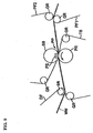
- a wet paper web WW shown by a broken line, which is transferred from right to left in the figure, is supported by press felts PF1 and PF2, a wet paper web transfer belt TB, and a dryer fabric DF.
- the press felts PF1 and PF2, the wet paper web transfer belt TB, and the dryer fabric DF, are endless belts supported by guide rollers GR.
- the wet paper web WW passes through a press part comprising a press roll PR, a concave shoe PS, which conforms to the shape of the press roll, and a shoe press belt SB.
- the wet paper web then moves past a suction roll SR.
- the press part and the suction roll structures are generally known.
- a continuous wet paper web WW passes successively through a wire part and a first press part. (The wire part and the first press part are not illustrated.)
- the wet web is carried from the first press part on press felt PF1, and is then transferred to press felt PF2, as shown in FIG. 9 .
- the press felt PF2 transfers the wet paper web to the press part PP.
- the wet paper web WW is pinched between by the press felt PF2 and the wet paper web transfer belt TB by the pressure applied by the press roll PR, and by the shoe PS through the shoe press belt SB.
- the press felt PF2 has high water permeability and the wet paper web transfer belt TB has low water permeability. Consequently, water in the wet paper web WW moves to the press felt PF2 at the press part PP.
- the wet paper web WW, and the wet paper web transfer belt TB move out of the press part, the pressure on them is suddenly released, and they expand in volume. This expansion, together with the capillary action of the pulp fibers forming the wet paper web WW, causes a rewetting phenomenon wherein part of water in the press felt PF2 moves back into to the wet paper web WW.
- the wet paper web transfer belt TB has very low permeability, it does not hold water. Therefore, rewetting from the wet paper web transfer belt TB does not occur, and the transfer belt TB contributes to improvement in the efficiency of water removal from the wet paper web.
- wet paper web WW moves out of the press part PP, it is transferred by the transfer belt TB to the suction roll SR, where the wet paper web is transferred to dryer fabric DF which carries the web through a drying process.
- wet paper web transfer belt TB There are several requirements for the proper operation of the wet paper web transfer belt TB.
- the wet paper web WW must be attached to the transfer belt TB, during transport, after the belt moves out of the press part PP.
- the wet paper web WW must be removable from the transfer belt TB smoothly when the web is transferred to the next stage of the papermaking process.
- the wet paper web transfer belt TB10 comprises a woven fabric 31, a high molecular weight elastic section 51 formed on one side of the woven fabric, and a batt layer 41 formed on the other side of the woven fabric.
- the wet paper web side layer TB11 of belt TB10 is formed by the high molecular weight elastic section 51 and the machine side layer TB12 is formed by the batt layer 41.
- the exposed surface of the wet paper web side layer TB11 is roughened by grinding.
- the ten-point average surface roughness Rz (according to JIS-B0601) is in the range of 0 to 20 microns while the belt is in the press part, and in the range of 2 to 80 microns after the belt moves out of the press part.
- the ten-point average roughness Rz, in the range of 0 to 20 microns in the press part is maintained for a short time after the belt moves out of the press part.
- the surface of the wet paper web side layer TB11 is smooth at this point. Therefore, a thin film of water may be formed between the wet paper web and the smooth surface of the wet paper web side layer TB11. The thin film of water causes the wet paper web to adhere to the surface of the wet paper web side layer TB11.
- the ten-point average surface roughness of its wet paper web side layer TB11 increases to a level within the range from 2 to 80 microns.
- the increase in the surface roughness of layer TB 11 breaks the thin water film, reducing the adhesion between the transfer belt and the wet paper web. Therefore, the wet paper web can be more easily transferred from the belt TB 10 to the next stage of the papermaking process.
- the transfer belt shown in Figure 10 meets the requirements described above for the proper operation of a wet paper web transfer belt by continually changing its surface roughness as it passes through the press part of the papermaking machine.
- the wet paper web side layer TB11 becomes worn, and the desirable effects resulting from the changing surface roughness of the belt diminish. Consequently, the belt becomes increasingly difficult to use over time.
- Japanese Patent No. 3264461 discloses an alternative transfer belt structure, as shown in Figure 11 , in which particles 60 of a filler protrude from the surface on the wet paper web side layer TB11.
- the size of the filler particles is exaggerated in FIG. 11 , since the actual particle size is in the order of a micron.
- the protruding filler particles 60 contribute to breaking of the thin water film.
- the use of a hydrophilic filler makes it possible for the thin water film which is formed after the belt moves out of the nip of the press part to concentrate at the locations of the protruding filler bodies 60 and thus be destroyed.
- Kaolin clay (hydrous silicic acid aluminum, having the general chemical formula Al 2 O 3 ⁇ 2SiO 2 ⁇ 2H 2 O) is used for the filler.
- the surface of the wet paper web side layer TB11 of the transfer belt is relatively smooth, there is a high likelihood that some filler bodies will separate from the surface of the belt, either during manufacture of the belt or during its use in the papermaking process.
- the filler which is mixed with liquefied high molecular weight elastic material, and the mixture is applied to a woven cloth 31 and then cured. After curing, the surface of the wet paper web side layer TB11 is ground, and in the grinding process some of the filler is scooped out. Filler can also separate from the belt in the paper-making process due to the high operating speeds and the strain in the belt resulting from the application of pressure in the press part of the machine. Because of the loss of filler, it has been difficult to obtain uniform physical properties in a transfer belt, and adequate durability. Thus it was difficult to produce a wet paper web transfer belt suitable for use over a long time.
- WO0127387 discloses a transfer belt for a paper machine, the transfer belt comprises a base structure and a fibre batt layer attached to the base structure and facing the fibre web. At least the fibre batt layer side of the belt is provided with a polymer matrix impregnating the fibre batt layer.
- the transfer belt fibre batt layer comprises at least two fibres with different surface properties.
- EP1096066 discloses a wet web transfer belt for a closed draw paper making machine which is provided with a rough surface to allow easy release of the wet web.
- the rough surface is formed from a welded layer of multiple fibre in which a filler material is incorporated.
- EP0576115 discloses a transfer belt for carrying a paper sheet in a paper machine from a press nip in a closed draw to a transfer point, where it is readily released.
- the belt comprises a supporting base with a particle filled polymer coating on its paper-facing surface, which surface has a pressure responsive recoverable degree of roughness.
- An object of this invention is to provide a wet paper web transfer belt which can be used for a long time, while fully meeting the requirements for attachment of the wet paper web to the belt during transport, and smooth removal of the wet paper web from the belt when the web is transferred to a next stage in the papermaking process.
- a wet paper web transfer belt for use in the press part of a closed draw papermaking machine, comprises comprising a base body, a machine side layer, and a wet paper web side layer, the wet paper web side layer having a wet paper web contacting surface and having porous bodies embedded therein.
- a plurality of the porous bodies, which comprise porous fibers, are exposed at the wet paper web contacting surface.
- the porous bodies protrude from the wet paper web side layer of the belt.
- the porous bodies resist falling off the belt because they are well-anchored in the wet web side layer, which is composed of a mixture of the porous bodies in a high molecular weight elastic material, preferably such as urethane resin, which enters the pores of the bodies.
- the transfer belt can transport an attached wet paper web, and release the web smoothly to a next stage in the papermaking process, over a long period of use.
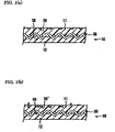
- FIG. 1 (a) is a cross-sectional schematic view, taken in the cross machine direction, of first embodiment of a wet paper web transfer belt according to the invention
- FIG. 1 (b) is a cross-sectional schematic view, taken in the cross machine direction, of a second embodiment of wet paper web transfer belt according to the invention:
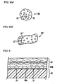
- FIG. 2 (a) is an enlarged view of a porous particle for use in the belt of FIG. 1(a) ;
- FIG. 2(b) is an enlarged oblique view of a porous fiber for use in the belt of FIG. 1(b) ;
- FIG. 3 is a first cross-sectional view illustrating the operation of a wet paper web transfer belt according to the invention
- FIG. 4 is a second cross-sectional view illustrating the operation of a wet paper web transfer belt according to the invention.
- FIG. 5 is a cross-sectional view of a wet paper web transfer belt in accordance with as embodiment of the invention.
- FIG.6 is a cross-sectional view of a wet paper web transfer belt of another embodiment according to the invention.
- FIG. 7 is a cross-sectional view of a wet paper web transfer belt of still another- embodiment: according to the invention.
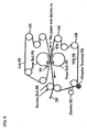
- FIG. 8 is a schematic view of an apparatus for evaluating the functional durability of wet paper web transfer belts
- FIG. 9 is a schematic view of a typical closed draw papermaking machine
- FIG. 10 is a cross-sectional view of a conventional wet paper web transfer belt.
- FIG. 11 is a cross-sectional view of another conventional wet paper web transfer belt.
- Each of the wet paper web transfer belts 10 of FIGS. 1(a) and 1(b) comprises a base body 30, a wet paper web side layer 11 and a machine side layer 12.
- the wet paper web side layer 11 is formed by a high molecular weight elastic material 50.
- porous bodies 20 are in the form of particles, as shown in detail in FIG. 2 (a) . These porous bodies are exposed at the surface of the wet paper web side layer 11.
- the porous bodies are in the form of porous fibers 20', as shown in detail in FIG. 2 (b) . Some of these porous fibers 2.0' are exposed at the surface of the wet paper web side layer 11 and some of the porous fibers 20' protrude from the surface of the layer 11.
- the high molecular weight, elastic material enters the pores of the porous bodies 20 and 20', thereby achieving a greater contact area between the elastic material and the bodies than in the case or non-porous bodies. Because the high molecular weight elastic material enters the pores of the bodies, and because of the greater contact area, the exposed and protruding bodies are firmly anchored in the wet paper web side layer 11. Thus, unlike an ordinary filler such as kaolin, etc. , which tends to fall off by itself during use even without being worn away, the porous bodies 20 and 20' tend to wear during use in the same way as the surrounding resin as a result of friction and abrasion. The distribution of the exposed porous bodies does not chance as a result of abrasion during use.
- a wet paper web transfer belt of the invention may be produced by mixing the porous bodies into a high molecular weight elastic material, forming the wet web side layer of a belt from the mixture, and then grinding the surface of the wet web side layer, and thereby either exposing porous bodies or causing them to protrude from the surface of the belt.
- porous fibers are intertwined with the outer surface of a base body by a process such as needle punching.
- a high molecular weight elastic material is then laid onto the porous fiber layer, forming a wet web side layer composed of porous fibers impregnated with the elastic material. Thereafter, the outer surface of the wet web side layer is ground to expose some of the porous fibers or to cause some of the fibers to protrude.
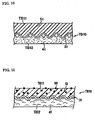
- FIG. 3 which is a cross-sectional view taken at the press part of a papermaking machine, a press felt PF, a wet paper web WW and a wet paper web transfer belt 10 are shown.
- the wet paper web WW is pinched between the press felt PF and the belt 10.
- the permeability of the wet paper web transfer belt 10 is either zero or very low.
- Water WA from the wet paper web WW forms a film between the wet paper web WW and the belt 10.
- FIG. 4 which shows press felt PF, the wet paper web WW, and the wet paper web transfer belt 10 after they have traveled beyond the press part.
- the porosity of the porous bodies improves their affinity for water, and causes water to concentrate at the locations of the exposed porous bodies.
- the water between the wet paper web WW and the belt 10 is drawn to the pores 21 of the porous bodies 20 by capillary action, and the water becomes concentrated at the locations of the exposed porous bodies, as shown in FIG. 4 .
- Porous fibers exhibit the same effect as non-fibrous porous filler bodies. Protruding porous fibers also draw water due to the effect of surface tension.
- the water held in the porous bodies 20 enables the wet paper web WW to remain attached to the wet paper web transfer belt 10.
- the web may be transferred smoothly from the belt 10 because the water is concentrated at the locations of the porous bodies and is not in the form of a continuous film, which would cause strong adhesion of the web to the belt.
- the use of porous bodies in the wet web side layer of the transfer belt enables the transfer belt to satisfy the requirements of adhesion of the wet web to the belt, and smooth release of the wet web from the belt, without depending on surface roughness of the high molecular weight elastic material which forms the wet paper web side layer.
- the size of the porous bodies 20 is preferably such that a rectangle, having the minimum area required to surround the pores of a porous body, has a larger side less than 10 ⁇ m in length. This length is shorter than an average pulp fiber in a wet paper web.
- the pores 21 are smaller than the average interval between pulp fibers in a wet paper web, water held in the pores 21 does not move back into to the wet paper web WW by capillary action immediately after the wet paper web moves out of the press part. Therefore, the porous bodies do not cause re-wetting.
- the area ratio of the exposed parts of the porous bodies 20 to the surface of the belt is preferably in the range from 5% to 50%.
- a ratio below 5% makes it difficult to remove the wet paper web from the wet paper web transfer belt, and a ratio above 50% causes the belt to lose its flexibility so that it no longer functions properly as a belt.
- the area ratio may be easily measured by photographing the surface of the belt with an electron microscope, scanning the picture into a computer, clarifying the picture using picture reading software such as "Photoshop5" from Adobe System Incorporated, and then calculating the areas of the porous bodies by the use of image processing software such as "NIH image" from the National Institutes of Health.
- porous body 20 having an average body diameter from 5 ⁇ m to 500 ⁇ m may be used.
- the porous filler may be inorganic or organic, and may be hydrophilic or hydrophobic.
- Diatomaceous earth (silicic acid: biolite, which contains more than 80% SiO 2 ) may be used as an inorganic porous filler.
- This product is available on the market as "RADIOLITE FINE FLOW B", a trademark of Showa Chemical Industry Co., Ltd.
- a high functional acrylic fiber may be used as an organic porous fiber.
- This product is available on the market as "BIOSAFE”, a trademark of Kanebo Synthetic Fiber Co., Ltd.
- wet paper web transfer belts according to the invention will be explained, with reference to FIGs. 5-7 .
- the wet paper web transfer belt 10 in FIG. 5 comprises a base body 30, a batt layer 40 comprising a batt fiber intertwiningly integrated with one side of the base body 30, and a high molecular weight elastic section 50 formed on the other side of the base body 30.
- the high molecular weight elastic section 50 constitutes the wet paper web side layer 11, and the batt layer 40 constitutes the machine side layer 12.
- the wet paper web side layer 11 may be obtained by mixing porous bodies 20 with liquid, high molecular weight, elastic material used to form the high molecular weight elastic section 50. After curing the high molecular weight elastic material containing the porous bodies 20, porous bodies are exposed by grinding the surface of the wet paper web side layer 11 with sandpaper, a whetstone, or the like.
- the machine side layer of the wet paper web transfer belt 10 comprises only batt fiber 40.
- a high molecular weight elastic material may be impregnated into this batt fiber 40 as shown in FIG. 6 .
- the machine side layer may be composed entirely of a high molecular weight elastic material 50 as shown in FIG. 7 , so that the transfer belt is formed without a batt fiber layer.
- a wet paper web transfer belt 10 according to the invention it include a wet paper web side layer 11 comprising a high molecular weight elastic section and porous bodies exposed on the surface of the wet paper web side layer 11.
- the porous bodies 20 are exposed by grinding the surface of the wet paper web side layer 11.
- the wet paper web side layer 11 of a wet paper web transfer belt 10 according to the invention contributes to the formation of an excellent paper surface since its web-contacting surface is smoother than the web-contacting surface of a press felt.
- thermosetting urethane resin or the like may be used as the material of the high molecular weight elastic section 50, and its Shore A hardness is desirably between 50 and 95.
- the wet paper web transfer belt according to the invention has no permeability.
- some papermaking machines requires a transfer belt having permeability.
- the desired belt structure may be obtained by reducing the amount of the impregnated high molecular weight elastic material, increasing the amount of grinding, or using a high molecular weight elastic material having open cells.
- the permeability of the belt is preferably 2cc/cm 2 /sec or less, measured by the test method for general woven fabric specified in JIS L 1096, using a fragile type testing machine.
- the base body 30 imparts strength to the wet paper web transfer belt. While a fabric woven with machine direction yarns and cross machine direction yarns is shown in FIGs. 5-7 , the base body is not limited to this structure, and may have various alternative structures as appropriate, such as, yarns in the machine direction and the cross machine direction which are overlapping rather than woven, or may be in the form of a film a knitted structure, or a wide belt-shaped body made by winding a narrow belt-shaped body in a helix.
- a wet paper web transfer belt having the structure shown in FIG. 5 was produced in the following process.
- An endless double woven fabric was obtained by weaving machine direction yarns and cross machine direction yarns of nylon-6 so that the basis weight of the double woven fabric was 600 g/m 2 .
- Staple fiber comprising nylon-6 and having an average fineness of 20 dtex was intertwiningly integrated with the outer surface of an endless woven fabric by needle punching.
- the basis weight of the staple fiber layer was 200g/m 2 .
- the fabric was then turned over, and the side which was not previously intertwiningly integrated with staple fiber became a new outer surface.
- staple fiber having an average fineness of 20 dtex was then intertwiningly integrated with the new outer surface by needle punching so that the basis weight of the staple fiber lawyer 200g/m 2
- a belt having a batt with a basis weight of 200g/m 2 on both sides was formed.
- One side of the structure was then coated with urethane resin containing a RADIOLITE FINE FLOW B as a porous filler.
- the porous filler was present in the mixture in an amount equal to 30% by weight relative to 100% by weight of the urethane resin was mixed.
- the average diameter of the porous bodies was 13.7 ⁇ m.
- the porosity of the porous bodies was 90%, and the main component of the porous material was SiO 2 .
- the outer surface was ground to a ten-point average surface roughness Rz of 15 ⁇ m.
- the grinding process exposed porous bodies on the surface of the resin layer, and completed the wet paper web transfer belt.
- a wet paper web transfer belt according to the invention was produced by the following process.
- An endless double woven fabric was obtained by weaving machine direction yarns and cross machine direction yarns of nylon-6 so that the basis weight of the double woven fabric was 600 g/m 2 .
- Staple fiber comprising nylon-6 and having an average fineness of 20 dtex was intertwiningly integrated with the outer surface of an endless woven fabric by needle punching.
- the basis weight of the staple fiber layer was 200g/m 2 .
- BIOSAFE staple fiber layer was pressed to make its density 0.4 g/cm 3 .
- the outer surface of the woven fabric was then impregnated with urethane resin and cured.
- the outer surface was ground to a ten-point average roughness Rz of 35 ⁇ m.
- the grinding process exposes porous bodies on the surface of the resin layer, and completed the wet paper web transfer belt.
- the structure shown in FIG. 11 was produced in the following process.
- An endless double woven fabric was obtained by weaving machine direction yarns and cross machine direction yarns of nylon-6 so that the basis weight of the double woven fabric was 600 g/m 2 .
- Staple fiber comprising nylon-6 and having an average fineness of 20 dtex was intertwiningly integrated with the outer surface of an endless woven fabric by needle punching.
- the basis weight of the staple fiber layer was 200g/m 2 .
- the fabric was then turned over, and the side which was not previously intertwiningly integrated with staple fiber became a new outer surface.
- staple fiber having an average fineness of 20 dtex was then intertwiningly integrated with the new outer surface by needle punching so that the basis weight of the staple fiber layer 200g/m 2 .
- a belt having a batt with a basis weight of 200g/m 2 on both sides was formed.
- the outer surface was ground to a ten-point average roughness Rz of 15 ⁇ m. This process caused kaolin clay to protrude from the surface of resin and completed the wet paper web transfer belt.
- Tests of the three wet paper web transfer belts were conducted by using an apparatus as shown in FIG. 8 .
- This experimental apparatus comprises a pair of press rolls PR forming a press part PP, a press felt PF pinched by the press rolls, and a wet paper web transfer belt TB.
- the press felt PF and the wet paper web transfer belt TB were supported under a predetermined tension by a plurality of guide rolls GR, and moved along with the rotation of the press rolls PR.
- SR is a suction roll and DF is a dryer fabric in FIG. 8 . While only a part of a dryer fabric DF is shown, the dryer fabric is endless, and is supported by guide rolls GR and driven by the wet paper web transfer belt TB.
- An abrasion terminal FR which comprises ultra high molecular weight polyethylene, is pushed against the wet paper web transfer belt TB to accelerate abrasion of the belt TB.
- a wet paper web WW was thrown on the wet paper web transfer belt TB on the upstream side relative to the press part PP.
- the wet paper web WW passed through the press part PP, and was transferred from the transfer belt TB to the dryer fabric DR by the suction roll SR.
- the wet paper transfer belts were run for 30 hours in these tests, and during the tests, the abrasion terminal FR continuously wore the wet paper web transfer belt TB. After the elapse of 30 hours, a wet paper web WW was thrown on the transfer belt TB once again. The test, therefore, compares a new wet paper web transfer belt TB with a worn belt.
- the driving speed of the apparatus was 150 m/min, the pressure at the press part was 40kg/cm, and the vacuum at the suction roll SR was 150 mm Hg.
- the wet paper web WW was composed of craft pulp, having an average basis weight of 80g/m 2 and a dryness of 38%.
- the press felt PF had a conventional structure, comprising a woven fabric and a batt layer which was intertwiningly integrated with the woven fabric by needle punching.
- the press felt had a basis weight of 1200g/m 2 , a batt fiber fineness of 10 dtex, and a felt density 0.45/cm 3
- the belt of the comparative example functioned efficiently when new because of the surface roughness resulting from grinding of the surface of the resin and the exposure of the kaolin clay in the manufacturing process.
- the surface of resin was worn smooth by the abrasion terminal FR, and the kaolin clay fell away.
- the water film between the belt and the wet paper web WW did not break, and therefore failure occurred in the transfer of the wet paper web WW to the drying stage.
- the transfer belt in accordance with the invention is advantageous because the porous bodies are anchored in the resin on the wet paper web side of the belt.
- the porous bodies resist falling off from the wet paper web side layer.
- the proper function of the belt, in which the wet paper web remains attached to the belt during transport but can be transferred smoothly to a next stage in the papermaking process, can be maintained over a very long period of time.
Landscapes
- Engineering & Computer Science (AREA)
- Power Engineering (AREA)
- Paper (AREA)
Claims (6)
- Une bande de transfert de feuille de papier continue humide (10) pour une utilisation dans la section des presses (PP) d'une machine à papier à tirage fermé, ladite bande (10) comportant un corps de base (30), une couche côté machine (12), et une couche côté feuille de papier continue humide (11) comportant un matériau élastique de poids moléculaire élevé, la couche côté feuille de papier continue humide (11) ayant une surface en contact avec la feuille de papier continue humide et ayant des fibres poreuses (20') intégrées en elle et ancrées par le matériau élastique de poids moléculaire élevé de la couche côté feuille de papier continue humide (11) dans des pores des parties intégrées des fibres poreuses (20'), où une pluralité desdites fibres poreuses (20') ont des parties exposées à ladite surface en contact avec la feuille de papier continue humide, et une pluralité desdites parties exposées des fibres poreuses (20') font saillie à partir de la couche côté feuille de papier continue humide (11) de telle sorte que de l'eau sur la surface en contact avec la feuille de papier continue humide peut être tirée jusque dans des pores des parties exposées des fibres poreuses (20') par action capillaire.
- Une bande de transfert de feuille de papier continue humide selon la revendication 1, où le rapport de surface des parties exposées des fibres poreuses (20') à la surface en contact avec la feuille de papier continue humide va de 5 % à 50 %.
- Une bande de transfert de feuille de papier continue humide selon n'importe quelle revendication précédente, où la porosité des fibres poreuses (20') est d'environ 60 %.
- Une machine à papier à tirage fermé comportant une section des presses (PP) et une bande de transfert de feuille de papier continue humide (10) agencée pour porter une feuille de papier continue humide à travers ladite section des presses (PP), ladite bande de transfert (10) comportant un corps de base (30), une couche côté machine (12), et une couche côté feuille de papier continue humide (11) comportant un matériau élastique de poids moléculaire élevé, la couche côté feuille de papier continue humide (11) ayant une surface en contact avec la feuille de papier continue humide et ayant des fibres poreuses (20') intégrées en elle et ancrées par le matériau élastique de poids moléculaire élevé de la couche côté feuille de papier continue humide (11) dans des pores des parties intégrées des fibres poreuses (20'), où une pluralité desdites fibres poreuses (20') ont des parties exposées à ladite surface en contact avec la feuille de papier continue humide, et une pluralité desdites parties exposées des fibres poreuses (20') font saillie à partir de la couche côté feuille de papier continue humide (11) de telle sorte que de l'eau sur la surface en contact avec la feuille de papier continue humide peut être tirée jusque dans des pores des parties exposées des fibres poreuses (20') par action capillaire.
- Une machine à papier à tirage fermé selon la revendication 4, où le rapport de surface des parties exposées des fibres poreuses (20') à la surface en contact avec la feuille de papier continue humide de la bande de transfert (10) va de 5 % à 50 %.
- Une machine à papier à tirage fermé selon la revendication 4 ou 5, où la porosité des fibres poreuses (20') de la bande de transfert (10) est d'environ 60 %.
Applications Claiming Priority (2)
| Application Number | Priority Date | Filing Date | Title |
|---|---|---|---|
| JP2003020471 | 2003-01-29 | ||
| JP2003020471A JP4036765B2 (ja) | 2003-01-29 | 2003-01-29 | 湿紙搬送用ベルト |
Publications (2)
| Publication Number | Publication Date |
|---|---|
| EP1443145A1 EP1443145A1 (fr) | 2004-08-04 |
| EP1443145B1 true EP1443145B1 (fr) | 2010-01-27 |
Family
ID=32652872
Family Applications (1)
| Application Number | Title | Priority Date | Filing Date |
|---|---|---|---|
| EP20040250474 Expired - Lifetime EP1443145B1 (fr) | 2003-01-29 | 2004-01-28 | Bande de transfert pour une bande de papier humide |
Country Status (8)
| Country | Link |
|---|---|
| US (1) | US7118650B2 (fr) |
| EP (1) | EP1443145B1 (fr) |
| JP (1) | JP4036765B2 (fr) |
| KR (1) | KR101147513B1 (fr) |
| CN (1) | CN100366819C (fr) |
| AT (1) | ATE456701T1 (fr) |
| CA (1) | CA2456616C (fr) |
| DE (1) | DE602004025305D1 (fr) |
Cited By (1)
| Publication number | Priority date | Publication date | Assignee | Title |
|---|---|---|---|---|
| CN101680179B (zh) * | 2007-06-11 | 2012-12-26 | 沃依特专利有限责任公司 | 用于制造单面平滑的纸幅面的机器和方法 |
Families Citing this family (17)
| Publication number | Priority date | Publication date | Assignee | Title |
|---|---|---|---|---|
| GB0204308D0 (en) * | 2002-02-23 | 2002-04-10 | Voith Fabrics Heidenheim Gmbh | Papermachine clothing |
| JP4041056B2 (ja) * | 2003-11-13 | 2008-01-30 | イチカワ株式会社 | 湿紙搬送用ベルト |
| JP2006144149A (ja) * | 2004-11-17 | 2006-06-08 | Ichikawa Co Ltd | 抄紙搬送フェルトおよび該抄紙搬送フェルトを備えた抄紙機のプレス装置 |
| JP3946221B2 (ja) * | 2004-11-30 | 2007-07-18 | ヤマウチ株式会社 | 製紙用弾性ベルト |
| JP2006176904A (ja) * | 2004-12-21 | 2006-07-06 | Ichikawa Co Ltd | 抄紙搬送フェルトおよび該抄紙搬送フェルトを備えた抄紙機のプレス装置 |
| DE102005046905A1 (de) * | 2005-09-30 | 2007-04-05 | Voith Patent Gmbh | Papiermaschinenbespannung |
| DE102006003707A1 (de) * | 2006-01-26 | 2007-08-02 | Voith Patent Gmbh | Transportband |
| US7500295B2 (en) * | 2006-07-05 | 2009-03-10 | American Linc, Llc | System, apparatus, and method of reducing production loss having a counterband |
| US8075738B2 (en) | 2006-10-27 | 2011-12-13 | Metso Paper Karlstad Ab | Apparatus with an impermeable transfer belt in a papermaking machine, and associated methods |
| US20080176690A1 (en) * | 2007-01-18 | 2008-07-24 | Lefkowitz Leonard R | Anti-rewet transfer belt |
| EP2206828B1 (fr) | 2007-09-18 | 2015-04-08 | Ichikawa Co., Ltd. | Tapis pour le transport d'une bande humide |
| AT505760B1 (de) * | 2008-01-09 | 2009-04-15 | Andritz Ag Maschf | Vorrichtung und verfahren zur entwasserung einer materialbahn |
| JP5551905B2 (ja) * | 2009-08-21 | 2014-07-16 | 旭化成せんい株式会社 | 微細繊維を含むシートの製造装置及び方法 |
| JP6389041B2 (ja) | 2014-02-03 | 2018-09-12 | イチカワ株式会社 | 湿紙搬送用ベルト |
| JP6389042B2 (ja) * | 2014-02-03 | 2018-09-12 | イチカワ株式会社 | 湿紙搬送用ベルト |
| JP6298011B2 (ja) * | 2015-05-28 | 2018-03-20 | イチカワ株式会社 | 湿紙搬送ベルト |
| US11098450B2 (en) | 2017-10-27 | 2021-08-24 | Albany International Corp. | Methods for making improved cellulosic products using novel press felts and products made therefrom |
Family Cites Families (14)
| Publication number | Priority date | Publication date | Assignee | Title |
|---|---|---|---|---|
| US4799998A (en) * | 1983-08-01 | 1989-01-24 | Albany International Corp. | Papermachine clothing |
| US4552620A (en) * | 1983-09-19 | 1985-11-12 | Beloit Corporation | Paper machine belt |
| CA1223764A (fr) * | 1983-10-19 | 1987-07-07 | August Murka, Jr. | Feutre de machine a papier |
| JPS61252389A (ja) * | 1985-04-25 | 1986-11-10 | 市川毛織株式会社 | 抄紙用加圧ベルト |
| US5298124A (en) | 1992-06-11 | 1994-03-29 | Albany International Corp. | Transfer belt in a press nip closed draw transfer |
| ES2192815T3 (es) * | 1999-07-08 | 2003-10-16 | Heimbach Gmbh Thomas Josef | Cinta de transferencia para una maquina papelera. |
| TW538175B (en) * | 1999-07-08 | 2003-06-21 | Heimbach Gmbh Thomas Josef | Transfer belt for a paper making machine |
| US6465074B1 (en) * | 1999-08-25 | 2002-10-15 | Albany International Corp. | Base substrates for coated belts |
| JP3488403B2 (ja) * | 1999-09-20 | 2004-01-19 | 市川毛織株式会社 | 湿紙搬送ベルト及びその製造方法 |
| FI111471B (fi) * | 1999-10-13 | 2003-07-31 | Tamfelt Oyj Abp | Siirtohihna paperikonetta varten |
| JP3443052B2 (ja) * | 1999-10-25 | 2003-09-02 | 市川毛織株式会社 | 湿紙搬送ベルト |
| US6383339B1 (en) * | 2000-03-30 | 2002-05-07 | Weavexx Corporation | Transfer belt |
| EP1162307B1 (fr) * | 2000-06-06 | 2003-11-12 | Thomas Josef Heimbach Gesellschaft mit beschränkter Haftung & Co. | Bande pour presse à patin pour machines à papier |
| JP2004124274A (ja) * | 2002-09-30 | 2004-04-22 | Ichikawa Woolen Textile Co Ltd | 湿紙搬送用ベルト |
-
2003
- 2003-01-29 JP JP2003020471A patent/JP4036765B2/ja not_active Expired - Lifetime
-
2004
- 2004-01-15 CN CNB2004100005957A patent/CN100366819C/zh not_active Expired - Lifetime
- 2004-01-26 US US10/764,618 patent/US7118650B2/en not_active Expired - Lifetime
- 2004-01-28 AT AT04250474T patent/ATE456701T1/de active
- 2004-01-28 EP EP20040250474 patent/EP1443145B1/fr not_active Expired - Lifetime
- 2004-01-28 DE DE200460025305 patent/DE602004025305D1/de not_active Expired - Lifetime
- 2004-01-28 CA CA 2456616 patent/CA2456616C/fr not_active Expired - Fee Related
- 2004-01-29 KR KR1020040005634A patent/KR101147513B1/ko not_active Expired - Fee Related
Cited By (1)
| Publication number | Priority date | Publication date | Assignee | Title |
|---|---|---|---|---|
| CN101680179B (zh) * | 2007-06-11 | 2012-12-26 | 沃依特专利有限责任公司 | 用于制造单面平滑的纸幅面的机器和方法 |
Also Published As
| Publication number | Publication date |
|---|---|
| US20040154776A1 (en) | 2004-08-12 |
| JP2004232118A (ja) | 2004-08-19 |
| ATE456701T1 (de) | 2010-02-15 |
| CN1519426A (zh) | 2004-08-11 |
| KR101147513B1 (ko) | 2012-05-21 |
| CA2456616A1 (fr) | 2004-07-29 |
| DE602004025305D1 (de) | 2010-03-18 |
| CA2456616C (fr) | 2012-04-24 |
| US7118650B2 (en) | 2006-10-10 |
| EP1443145A1 (fr) | 2004-08-04 |
| JP4036765B2 (ja) | 2008-01-23 |
| CN100366819C (zh) | 2008-02-06 |
| KR20040070045A (ko) | 2004-08-06 |
Similar Documents
| Publication | Publication Date | Title |
|---|---|---|
| CA2456616C (fr) | Courroie de transfert de bande de papier humide | |
| US5298124A (en) | Transfer belt in a press nip closed draw transfer | |
| JP4064930B2 (ja) | プレスフェルト | |
| EP1531198B1 (fr) | Bande pour transférer une bande de papier humide | |
| US5753085A (en) | Textile substrate for a long nip press belt | |
| CA2442440C (fr) | Courroie de transfert de bande continue de papier humide | |
| EP1460172A1 (fr) | Bande pour transférer une bande de papier humide | |
| EP2907919B1 (fr) | Courroie de transfert d'une bande de papier humide | |
| EP2213788A1 (fr) | Courroie de support pour bande de papier humide | |
| EP1959055B1 (fr) | Bande de transfert pour machine à papier | |
| EP2902545B1 (fr) | Bande de transfert d'une bande de papier humide | |
| EP0987366A2 (fr) | Feutre de presse à essorage amélioré | |
| WO2000052263A1 (fr) | Toile de transfert |
Legal Events
| Date | Code | Title | Description |
|---|---|---|---|
| PUAI | Public reference made under article 153(3) epc to a published international application that has entered the european phase |
Free format text: ORIGINAL CODE: 0009012 |
|
| AK | Designated contracting states |
Kind code of ref document: A1 Designated state(s): AT BE BG CH CY CZ DE DK EE ES FI FR GB GR HU IE IT LI LU MC NL PT RO SE SI SK TR |
|
| AX | Request for extension of the european patent |
Extension state: AL LT LV MK |
|
| 17P | Request for examination filed |
Effective date: 20050131 |
|
| AKX | Designation fees paid |
Designated state(s): AT BE BG CH CY CZ DE DK EE ES FI FR GB GR HU IE IT LI LU MC NL PT RO SE SI SK TR |
|
| 17Q | First examination report despatched |
Effective date: 20070612 |
|
| GRAP | Despatch of communication of intention to grant a patent |
Free format text: ORIGINAL CODE: EPIDOSNIGR1 |
|
| GRAS | Grant fee paid |
Free format text: ORIGINAL CODE: EPIDOSNIGR3 |
|
| GRAA | (expected) grant |
Free format text: ORIGINAL CODE: 0009210 |
|
| AK | Designated contracting states |
Kind code of ref document: B1 Designated state(s): AT BE BG CH CY CZ DE DK EE ES FI FR GB GR HU IE IT LI LU MC NL PT RO SE SI SK TR |
|
| REG | Reference to a national code |
Ref country code: GB Ref legal event code: FG4D |
|
| REG | Reference to a national code |
Ref country code: CH Ref legal event code: EP |
|
| REG | Reference to a national code |
Ref country code: IE Ref legal event code: FG4D |
|
| REF | Corresponds to: |
Ref document number: 602004025305 Country of ref document: DE Date of ref document: 20100318 Kind code of ref document: P |
|
| REG | Reference to a national code |
Ref country code: SE Ref legal event code: TRGR |
|
| REG | Reference to a national code |
Ref country code: NL Ref legal event code: VDEP Effective date: 20100127 |
|
| PG25 | Lapsed in a contracting state [announced via postgrant information from national office to epo] |
Ref country code: NL Free format text: LAPSE BECAUSE OF FAILURE TO SUBMIT A TRANSLATION OF THE DESCRIPTION OR TO PAY THE FEE WITHIN THE PRESCRIBED TIME-LIMIT Effective date: 20100127 Ref country code: ES Free format text: LAPSE BECAUSE OF FAILURE TO SUBMIT A TRANSLATION OF THE DESCRIPTION OR TO PAY THE FEE WITHIN THE PRESCRIBED TIME-LIMIT Effective date: 20100508 Ref country code: PT Free format text: LAPSE BECAUSE OF FAILURE TO SUBMIT A TRANSLATION OF THE DESCRIPTION OR TO PAY THE FEE WITHIN THE PRESCRIBED TIME-LIMIT Effective date: 20100527 |
|
| PG25 | Lapsed in a contracting state [announced via postgrant information from national office to epo] |
Ref country code: MC Free format text: LAPSE BECAUSE OF NON-PAYMENT OF DUE FEES Effective date: 20100131 Ref country code: SI Free format text: LAPSE BECAUSE OF FAILURE TO SUBMIT A TRANSLATION OF THE DESCRIPTION OR TO PAY THE FEE WITHIN THE PRESCRIBED TIME-LIMIT Effective date: 20100127 |
|
| REG | Reference to a national code |
Ref country code: CH Ref legal event code: PL |
|
| PG25 | Lapsed in a contracting state [announced via postgrant information from national office to epo] |
Ref country code: BE Free format text: LAPSE BECAUSE OF FAILURE TO SUBMIT A TRANSLATION OF THE DESCRIPTION OR TO PAY THE FEE WITHIN THE PRESCRIBED TIME-LIMIT Effective date: 20100127 Ref country code: GR Free format text: LAPSE BECAUSE OF FAILURE TO SUBMIT A TRANSLATION OF THE DESCRIPTION OR TO PAY THE FEE WITHIN THE PRESCRIBED TIME-LIMIT Effective date: 20100428 Ref country code: CH Free format text: LAPSE BECAUSE OF NON-PAYMENT OF DUE FEES Effective date: 20100131 Ref country code: RO Free format text: LAPSE BECAUSE OF FAILURE TO SUBMIT A TRANSLATION OF THE DESCRIPTION OR TO PAY THE FEE WITHIN THE PRESCRIBED TIME-LIMIT Effective date: 20100127 Ref country code: CY Free format text: LAPSE BECAUSE OF FAILURE TO SUBMIT A TRANSLATION OF THE DESCRIPTION OR TO PAY THE FEE WITHIN THE PRESCRIBED TIME-LIMIT Effective date: 20100127 Ref country code: EE Free format text: LAPSE BECAUSE OF FAILURE TO SUBMIT A TRANSLATION OF THE DESCRIPTION OR TO PAY THE FEE WITHIN THE PRESCRIBED TIME-LIMIT Effective date: 20100127 Ref country code: LI Free format text: LAPSE BECAUSE OF NON-PAYMENT OF DUE FEES Effective date: 20100131 |
|
| PG25 | Lapsed in a contracting state [announced via postgrant information from national office to epo] |
Ref country code: BG Free format text: LAPSE BECAUSE OF FAILURE TO SUBMIT A TRANSLATION OF THE DESCRIPTION OR TO PAY THE FEE WITHIN THE PRESCRIBED TIME-LIMIT Effective date: 20100427 Ref country code: CZ Free format text: LAPSE BECAUSE OF FAILURE TO SUBMIT A TRANSLATION OF THE DESCRIPTION OR TO PAY THE FEE WITHIN THE PRESCRIBED TIME-LIMIT Effective date: 20100127 Ref country code: SK Free format text: LAPSE BECAUSE OF FAILURE TO SUBMIT A TRANSLATION OF THE DESCRIPTION OR TO PAY THE FEE WITHIN THE PRESCRIBED TIME-LIMIT Effective date: 20100127 |
|
| PLBE | No opposition filed within time limit |
Free format text: ORIGINAL CODE: 0009261 |
|
| STAA | Information on the status of an ep patent application or granted ep patent |
Free format text: STATUS: NO OPPOSITION FILED WITHIN TIME LIMIT |
|
| 26N | No opposition filed |
Effective date: 20101028 |
|
| PG25 | Lapsed in a contracting state [announced via postgrant information from national office to epo] |
Ref country code: IE Free format text: LAPSE BECAUSE OF NON-PAYMENT OF DUE FEES Effective date: 20100128 Ref country code: DK Free format text: LAPSE BECAUSE OF FAILURE TO SUBMIT A TRANSLATION OF THE DESCRIPTION OR TO PAY THE FEE WITHIN THE PRESCRIBED TIME-LIMIT Effective date: 20100127 |
|
| PGFP | Annual fee paid to national office [announced via postgrant information from national office to epo] |
Ref country code: IT Payment date: 20101223 Year of fee payment: 8 |
|
| PG25 | Lapsed in a contracting state [announced via postgrant information from national office to epo] |
Ref country code: HU Free format text: LAPSE BECAUSE OF FAILURE TO SUBMIT A TRANSLATION OF THE DESCRIPTION OR TO PAY THE FEE WITHIN THE PRESCRIBED TIME-LIMIT Effective date: 20100728 Ref country code: LU Free format text: LAPSE BECAUSE OF NON-PAYMENT OF DUE FEES Effective date: 20100128 |
|
| PG25 | Lapsed in a contracting state [announced via postgrant information from national office to epo] |
Ref country code: TR Free format text: LAPSE BECAUSE OF FAILURE TO SUBMIT A TRANSLATION OF THE DESCRIPTION OR TO PAY THE FEE WITHIN THE PRESCRIBED TIME-LIMIT Effective date: 20100127 |
|
| PG25 | Lapsed in a contracting state [announced via postgrant information from national office to epo] |
Ref country code: IT Free format text: LAPSE BECAUSE OF NON-PAYMENT OF DUE FEES Effective date: 20120128 |
|
| REG | Reference to a national code |
Ref country code: FR Ref legal event code: PLFP Year of fee payment: 13 |
|
| PGFP | Annual fee paid to national office [announced via postgrant information from national office to epo] |
Ref country code: FR Payment date: 20151208 Year of fee payment: 13 |
|
| PGFP | Annual fee paid to national office [announced via postgrant information from national office to epo] |
Ref country code: AT Payment date: 20151223 Year of fee payment: 13 |
|
| REG | Reference to a national code |
Ref country code: AT Ref legal event code: MM01 Ref document number: 456701 Country of ref document: AT Kind code of ref document: T Effective date: 20170128 |
|
| REG | Reference to a national code |
Ref country code: FR Ref legal event code: ST Effective date: 20170929 |
|
| PG25 | Lapsed in a contracting state [announced via postgrant information from national office to epo] |
Ref country code: FR Free format text: LAPSE BECAUSE OF NON-PAYMENT OF DUE FEES Effective date: 20170131 Ref country code: AT Free format text: LAPSE BECAUSE OF NON-PAYMENT OF DUE FEES Effective date: 20170128 |
|
| PGFP | Annual fee paid to national office [announced via postgrant information from national office to epo] |
Ref country code: SE Payment date: 20221212 Year of fee payment: 20 Ref country code: GB Payment date: 20221208 Year of fee payment: 20 |
|
| PGFP | Annual fee paid to national office [announced via postgrant information from national office to epo] |
Ref country code: FI Payment date: 20230109 Year of fee payment: 20 |
|
| PGFP | Annual fee paid to national office [announced via postgrant information from national office to epo] |
Ref country code: DE Payment date: 20221207 Year of fee payment: 20 |
|
| REG | Reference to a national code |
Ref country code: DE Ref legal event code: R071 Ref document number: 602004025305 Country of ref document: DE |
|
| REG | Reference to a national code |
Ref country code: GB Ref legal event code: PE20 Expiry date: 20240127 |
|
| REG | Reference to a national code |
Ref country code: SE Ref legal event code: EUG |
|
| PG25 | Lapsed in a contracting state [announced via postgrant information from national office to epo] |
Ref country code: GB Free format text: LAPSE BECAUSE OF EXPIRATION OF PROTECTION Effective date: 20240127 |