EP1443169B1 - Elément de renforcement à monter entre deux profilés en matière plastique de cadres dormants contigus - Google Patents
Elément de renforcement à monter entre deux profilés en matière plastique de cadres dormants contigus Download PDFInfo
- Publication number
- EP1443169B1 EP1443169B1 EP04001550A EP04001550A EP1443169B1 EP 1443169 B1 EP1443169 B1 EP 1443169B1 EP 04001550 A EP04001550 A EP 04001550A EP 04001550 A EP04001550 A EP 04001550A EP 1443169 B1 EP1443169 B1 EP 1443169B1
- Authority
- EP
- European Patent Office
- Prior art keywords
- reinforcing element
- cross
- piece
- element according
- cover strip
- Prior art date
- Legal status (The legal status is an assumption and is not a legal conclusion. Google has not performed a legal analysis and makes no representation as to the accuracy of the status listed.)
- Expired - Lifetime
Links
- 229920003023 plastic Polymers 0.000 title claims abstract description 28
- 239000004033 plastic Substances 0.000 title claims abstract description 28
- 230000003014 reinforcing effect Effects 0.000 title claims description 52
- 238000007789 sealing Methods 0.000 claims description 14
- 239000000463 material Substances 0.000 claims 5
- 230000004308 accommodation Effects 0.000 claims 3
- 238000007373 indentation Methods 0.000 claims 3
- 238000005728 strengthening Methods 0.000 abstract 1
- 210000002414 leg Anatomy 0.000 description 16
- 239000002184 metal Substances 0.000 description 6
- 238000004519 manufacturing process Methods 0.000 description 3
- 238000005553 drilling Methods 0.000 description 2
- 210000003414 extremity Anatomy 0.000 description 2
- 238000009413 insulation Methods 0.000 description 2
- 239000012212 insulator Substances 0.000 description 2
- 238000000465 moulding Methods 0.000 description 2
- 238000004026 adhesive bonding Methods 0.000 description 1
- 238000010276 construction Methods 0.000 description 1
- 230000008878 coupling Effects 0.000 description 1
- 238000010168 coupling process Methods 0.000 description 1
- 238000005859 coupling reaction Methods 0.000 description 1
- 238000003780 insertion Methods 0.000 description 1
- 230000037431 insertion Effects 0.000 description 1
- 230000000149 penetrating effect Effects 0.000 description 1
- 230000008092 positive effect Effects 0.000 description 1
- 230000005855 radiation Effects 0.000 description 1
- 230000002787 reinforcement Effects 0.000 description 1
- 230000000284 resting effect Effects 0.000 description 1
- 239000007787 solid Substances 0.000 description 1
- 210000000689 upper leg Anatomy 0.000 description 1
- 238000003466 welding Methods 0.000 description 1
Images


Classifications
-
- E—FIXED CONSTRUCTIONS
- E06—DOORS, WINDOWS, SHUTTERS, OR ROLLER BLINDS IN GENERAL; LADDERS
- E06B—FIXED OR MOVABLE CLOSURES FOR OPENINGS IN BUILDINGS, VEHICLES, FENCES OR LIKE ENCLOSURES IN GENERAL, e.g. DOORS, WINDOWS, BLINDS, GATES
- E06B1/00—Border constructions of openings in walls, floors, or ceilings; Frames to be rigidly mounted in such openings
- E06B1/56—Fastening frames to the border of openings or to similar contiguous frames
- E06B1/60—Fastening frames to the border of openings or to similar contiguous frames by mechanical means, e.g. anchoring means
- E06B1/6007—Fastening frames to the border of openings or to similar contiguous frames by mechanical means, e.g. anchoring means between similar contiguous frames
Definitions
- the invention relates to a reinforcing element for the arrangement between two plastic profiles of adjacent frame, in particular of plastic windows and / or - doors, which extends over the entire length of the plastic profiles and on each longitudinal side has a receptacle for the frictional fixing a fastening web of a cover strip.
- this connection can absorb the forces that occur on the one hand and on the other hand is both waterproof and as poor as possible thermally conductive.
- reinforcing elements between the adjacent frame hollow profiles or solid profiles are used in practice, which are fixed by means of coupling screws to the adjacent plastic profiles.
- DE 198 55 966 A1 discloses a reinforcing element for window frames, facades or the like with an inner part extending to the inside of the frame and an outer part extending to the outside of the frame, wherein the two parts are thermally separated from one another.
- one of the parts made of metal and the other is made as an insulator and another thermal insulator connects the inner and outer parts together.
- This multi-part reinforcing element is expensive to manufacture and therefore expensive.
- US-A-5 435 106 shows a reinforcing member for a window frame having recesses for insertion into window frame-side recesses.
- the free ends of the reinforcing element each have one flat cross section and a cover strip is mounted in a clip recess of the window frame.
- DE 88 11 361 U1 describes a reinforcing element for window frames, which is composed of two identical but mirror images of each other arranged sheet metal profiles, wherein the sheet metal profiles are inextricably linked together in their central region by riveting, welding, gluing or otherwise.
- the object is achieved by a cross-sectionally T-shaped configuration of the reinforcing element, wherein the foot and the web are each provided centrally with the receptacle for the mounting web of the cover strip, the foot associated with recording for the cover strip widens to a chamber in the web and the foot and the bridge are made in one piece from a sheet metal.
- the reinforcing element is to be used in conjunction with all plastic profiles customary in window construction, since the foot or the web can protrude beyond the inside or outside of the plastic profile of the window frame and is covered by the cover strip.
- the air-filled chamber has a positive effect on the heat-insulating properties of the reinforcing element from and the one-piece production can be done for example by roll forming.
- the foot is preferably at each of its longitudinal sides 180 ° outwardly mortared and has a cross-sectionally V-shaped inlet slope for the fastening web.
- the foot is expediently mortared on each of its longitudinal sides by 180 ° inwards.
- the chamber is divided by a constriction of the web, wherein the foot facing away from the chamber portion for receiving at least one building side to be fastened holding bracket is used.
- the inclusion of a top and bottom bracket to be arranged in the chamber portion can be positive or non-positive and ensures high stability of the two adjacent frame, which, as usual, are bolted together.
- the web associated recording for the cover strip is U-shaped, wherein the two legs of the receptacle extending parallel to the outer contour of the web and the leg connecting web bounds the chamber.
- each trim strip is advantageously provided on the longitudinal side facing the fastening web with a recess for receiving sealing strips.
- the sealing strips are formed as sealing lips, which are arranged in the recess, that they covered by the cover strip on the respective associated plastic profile sealingly rest.
- a groove for receiving the free end of the web is embedded in the recess of the cover strip on both sides of the fastening web.
- the web which can protrude over the one side of the frame in the connection of frame with a relatively small thickness, thus immersed in the groove of the cover strip and is completely covered by the cover strip, so that it does not interfere visually.
- the rectangular bracket preferably consists of a flange plate and an angle leg, wherein the flange plate is provided with holes for attaching the building side and the angle leg extends frontally into the chamber portion.
- the angle leg of the bracket is provided with a 2-dimensionally adjustable holder for receiving a roller shutter shaft.
- the bracket formed in this way is used for the upper attachment of the reinforcing element and avoids the construction-side arrangement of additional bearings for roller shutter shafts, wherein the holder is adjustable both in height and in depth.
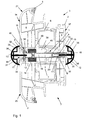
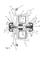
- the reinforcing element 1 is arranged between two plastic profiles of adjacent frame 3.
- Each of the plastic profiles 2 is provided with longitudinally extending hollow chambers 4 and has a seal 5, which serves as a stop for a sash frame, not shown.
- a reinforcing profile 6 is used, in the area of holes 7 are arranged for screwing the plastic profiles 2.
- the reinforcing element 1 is formed in cross-section T-shaped with a foot 8 and a web 9, which in one piece are made of a metallic sheet.
- a foot 8 and a web 9, which in one piece are made of a metallic sheet are mortared at each of its longitudinal sides 10 by 180 ° inwards.
- the foot 8 is mortared at each of its longitudinal sides 10 by 180 ° to the outside and has a directed into the open inlet slope 41 with a V-shaped cross-section.
- a slot-shaped receptacle 11 for non-positive fixing of a fastening web 12 of a trim strip 13 is provided in the middle of the foot 8.
- the receptacle 11 opens into a divided by a constriction 14 of the web 9 chamber 15, the foot 8 facing away from the chamber portion 16 is limited by a web 9 associated receptacle 17 for the cover strip 13.
- a web 9 associated receptacle 17 for the cover strip 13 instead of introducing the constriction 14, it is also possible for the web 9 in such a way on both sides to inwardly that interlocking support arms 42 each with end-side bend the chamber 15 of the web 9 subdivide.
- the centrally inserted into the free end of the web 9 receptacle 17 is U-shaped in cross-section, wherein the two legs 19 of the receptacle 17 parallel to the outer contour of the web 9 and the limbs 19 limiting web 20 limits the chamber portion 16.
- the two legs 19 open via a 180 ° bend in the web 9, whereby the one-piece part of the reinforcing element 1 is made. Due to the chamber 15 and the chamber portion 16 in the web 9, the reinforcing element 1 has a relatively poor thermal conductivity.
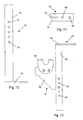
- the first frame 23 is first fixed to the building. Subsequently, each end face an angle leg 22 of a bracket 23 is inserted into the chamber portion 16 of the web 9 of the reinforcing element 1 such that a welded to the angle leg end flange plate 24 in the assembly of the reinforcing element in the direction of the second frame 25 has. Now, the reinforcing element 1 is brought into abutment with the first frame and attached by means of holes 26 of the flange 24 piercing screw on the building. Subsequently, the second frame 25 is attached to the reinforcing element 1 and also attached to the building side.
- first frame 21 and the second frame 25 are screwed together while penetrating the reinforcing element 1.
- the chamber section 16 is loaded by the two frame frames 21, 25 in such a way that the angle leg 22 of the holding bracket 23 is held in a non-positive manner in the chamber section 16 of the chamber 15.
- a holder 27 for supporting a roller shutter shaft is attached to the angle leg 22 of the upper bracket 23.
- the holder 27 is composed of an angle leg 22 associated with the flange plate 28 and a bearing member 29, wherein the bearing member 29 is bolted to the flange 28 and this in turn with the angle leg 22.
- the angle leg 22 has a plurality of spaced-apart through holes 30.
- the cover strip 13 is provided with sealing lips 32 formed as sealing strips 33, wherein in each case a sealing lip 32 a on an outer side 34 of the frame 3 resting longitudinal side of the cover strip 13 is associated.
- the sealing lips 32 are inserted into a recess 35 of the trim strip 13. Into the recess 35 12 adjacent grooves 36 are incorporated directly to the mounting bar.
- the thickness of the frame 3 is dimensioned larger than the width of the reinforcing element 1, so that both the free end of the foot 8 and the free end of the web 9 behind the outside 34 and the inside 37 of the frame 3 back, the foot 8 is inserted into chambers 38 of the frame 3.
- the web 9 carries in the region of the constriction 14 insulating elements 39 which protrude into chambers 38 of the frame 3 and there are supported on a boundary web 40.
- Both in the receptacle 11 of the foot 8 and in the receptacle 17 of the web 9 each have a profiled mounting web 12 of a substantially semicircular cross-sectional molding strip 13 is inserted such that the sealing lips 32 of the molding strips 13 sealingly on the outside 34 and the inside 37 of the frame 3 come to rest.
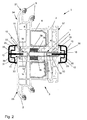
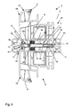
- the reinforcing element 1 is arranged according to FIGS. 2 and 7 between two frame 3, which compared to the frame 3 of FIG. 1 have a smaller thickness, which is why the free end 18 of the web 9 protrudes slightly beyond the inside 37 of the frame 3. It protrudes into the recess 35 of the associated trim strip 13, wherein both trim strips 13 are formed flattened frontally.
- the foot 8 of the reinforcing element 1 is again in opposite chambers 38 of the frame 3 used.
- the insulation elements 39 used in chambers 38 of the frame 3 are based on the web 9 of the reinforcing element 1 and on the boundary webs 40 of the frame 3 on the one hand.
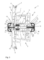
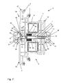
- the frame 3 according to FIGS. 3 and 8 are formed reduced in thickness relative to the frame 3 of FIG. 2, so that the free end 18 of the web 9 projects into the grooves 36 of the associated cover strip 13.
- the foot 8 of the reinforcing element 1 is in turn defined in chambers 38 of the frame 3.
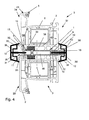
- the two side trim strips 13 are essentially trapezoidal in cross section.
- the frame 3 according to FIGS. 5 and 9 are again reduced in thickness relative to the frame 3 according to FIG. 3, so that on the one hand the foot 8 of the reinforcing element 1 rests on the outside 34 of the adjacent frame and in the recess 35 of the associated cover strip 13 protrudes and the free end 18 of the web 9 engages in the grooves 36 of the associated trim strip 13.
Landscapes
- Engineering & Computer Science (AREA)
- Mechanical Engineering (AREA)
- Civil Engineering (AREA)
- Structural Engineering (AREA)
- Door And Window Frames Mounted To Openings (AREA)
- Operating, Guiding And Securing Of Roll- Type Closing Members (AREA)
- Body Structure For Vehicles (AREA)
- Panels For Use In Building Construction (AREA)
- Window Of Vehicle (AREA)
- Wing Frames And Configurations (AREA)
Claims (13)
- Élément de renfort à disposer entre deux profilés en matière plastique (2) de châssis dormants voisins (3, 21, 25), en particulier de fenêtres et/ou de portes en matière plastique, lequel s'étend sur toute la longueur des profilés en matière plastique (2) et comporte, sur chaque côté longitudinal, un logement (11, 17) pour la fixation par conjugaison de forces d'une patte de fixation (12) d'une baguette de parement (13), caractérisé par une configuration à section transversale en T, le pied (8) et la membrure (9) étant chacun pourvus centralement du logement (11, 17) pour la patte de fixation (12) de la baguette de parement (13), le logement (11) associé au pied (8) et destiné à la baguette de parement (13) s'élargissant dans la membrure (9) sous la forme d'un compartiment (15), et le pied (8) et la membrure (9) étant réalisés d'un seul tenant dans une même tôle.
- Élément de renfort selon la revendication 1, caractérisé en ce que, sur chacun de ses côtés longitudinaux (10), le pied (8) est replié à 180° vers l'extérieur et comporte un biseau d'insertion à section transversale en V (41) pour la patte de fixation (12).
- Élément de renfort selon la revendication 1, caractérisé en ce que, sur chacun de ses côtés longitudinaux (10), le pied (8) est replié à 180° vers l'intérieur.
- Élément de renfort selon la revendication 1, caractérisé en ce que le compartiment (15) est divisé par un rétrécissement (14) de la membrure (9).
- Élément de renfort selon la revendication 1, caractérisé en ce que la membrure (9) est repliée des deux côtés vers l'intérieur, de façon à former des bras de retenue (42) qui sont emboîtés l'un dans l'autre et comportent chacun une portion coudée à leur extrémité et qui divisent le compartiment (15) de la membrure (9).
- Élément de renfort selon la revendication 4 ou 5, caractérisé en ce que la portion de compartiment (16) orientée à l'opposé du pied (8) sert à recevoir au moins une équerre de retenue (23) à fixer côté bâtiment.
- Élément de renfort selon une des revendications 1 à 6, caractérisé en ce que le logement (17) associé à la membrure (9) et destiné à la baguette de parement (13) est conformé en U, les deux branches (19) du logement (17) s'étendant parallèlement au contour extérieur de la membrure (9), et la membrure (20) qui relie les branches (19) limitant le compartiment (15).
- Élément de renfort selon la revendication 1, caractérisé en ce que chaque baguette de parement (13) est pourvue, sur le côté longitudinal tourné vers la patte de fixation (12), d'un renfoncement (35) pour recevoir des baguettes d'étanchéité (33).
- Élément de renfort selon la revendication 8, caractérisé en ce que les baguettes d'étanchéité (33) sont conformées en lèvres d'étanchéité (32), lesquelles sont disposées dans le renfoncement (35) de façon à reposer de manière étanche sur le profilé en matière plastique (2) qui leur est associé en étant recouvertes par la baguette de parement (13).
- Élément de renfort selon une des revendications 1 à 9, caractérisé en ce que, des deux côtés de la patte de fixation (12), une rainure (36) est ménagée dans le renfoncement (35) de la baguette de parement (13) pour recevoir l'extrémité libre (18) de la membrure (9).
- Élément de renfort selon une des revendications 1 à 10, caractérisé en ce que la membrure (9) porte des éléments isolants (39) qui pénètrent dans des compartiments (38) des profilés en matière plastique (2).
- Élément de renfort selon la revendication 6, caractérisé en ce que l'équerre de retenue à angle droit (23) est constituée d'une plaque de semelle (24) et d'une aile d'équerre (22), la plaque de semelle (24) étant pourvue de trous (26) pour la fixation côté bâtiment, et l'aile d'équerre (22) s'étendant frontalement dans la portion de compartiment (16).
- Élément de renfort selon la revendication 12, caractérisé en ce que l'aile d'équerre (22) de l'équerre de retenue (23) est munie d'un support (27) réglable dans deux dimensions pour recevoir un arbre de volet roulant.
Applications Claiming Priority (2)
| Application Number | Priority Date | Filing Date | Title |
|---|---|---|---|
| DE10304389 | 2003-02-03 | ||
| DE10304389A DE10304389B4 (de) | 2003-02-03 | 2003-02-03 | Verstärkungselement zur Anordnung zwischen zwei Kunststoffprofilen benachbarter Blendrahmen |
Publications (3)
| Publication Number | Publication Date |
|---|---|
| EP1443169A2 EP1443169A2 (fr) | 2004-08-04 |
| EP1443169A3 EP1443169A3 (fr) | 2005-04-20 |
| EP1443169B1 true EP1443169B1 (fr) | 2007-04-25 |
Family
ID=32603136
Family Applications (1)
| Application Number | Title | Priority Date | Filing Date |
|---|---|---|---|
| EP04001550A Expired - Lifetime EP1443169B1 (fr) | 2003-02-03 | 2004-01-26 | Elément de renforcement à monter entre deux profilés en matière plastique de cadres dormants contigus |
Country Status (3)
| Country | Link |
|---|---|
| EP (1) | EP1443169B1 (fr) |
| AT (1) | ATE360740T1 (fr) |
| DE (2) | DE10304389B4 (fr) |
Families Citing this family (2)
| Publication number | Priority date | Publication date | Assignee | Title |
|---|---|---|---|---|
| DE102007026749A1 (de) * | 2007-06-09 | 2008-12-11 | Profine Gmbh | Verbindungsprofil |
| DK178524B1 (en) | 2013-06-21 | 2016-05-23 | Vkr Holding As | A window arrangement comprising a plurality of window systems and at least one accessory element |
Family Cites Families (8)
| Publication number | Priority date | Publication date | Assignee | Title |
|---|---|---|---|---|
| DE8708611U1 (de) * | 1987-06-20 | 1987-10-22 | Over, Christa Maria | Träger für Fensterrahmen |
| DE8811361U1 (de) * | 1988-09-08 | 1988-10-27 | Over, Helmut, 5352 Zülpich | Befestigungsmittel für einen Träger für Fensterrahmen |
| DE3929716A1 (de) * | 1989-01-25 | 1990-08-02 | Helmut Over | Fensterband mit abstandselementen |
| DE4107743A1 (de) * | 1990-03-09 | 1992-01-23 | Rudolf Strobel | Pfosten bzw. pfette fuer eine leichtbauwand aus bauelementen, insbesondere kunststoffenstern |
| US5435106A (en) * | 1994-01-18 | 1995-07-25 | Aluminum Company Of America | Metal reinforced mullion for windows |
| DE19855966A1 (de) * | 1998-03-27 | 1999-09-30 | Helmut Over | Träger für Fensterrahmen, Fassaden oder dergleichen |
| DE10028802A1 (de) * | 2000-06-15 | 2001-12-20 | Helmut Over | Bauelement und Verwendung eines Trägers sowie Verfahren zur Herstellung eines Fassadenelementes |
| US6662512B2 (en) * | 2000-06-30 | 2003-12-16 | Certainteed Corporation | Two-piece mullion reinforcement |
-
2003
- 2003-02-03 DE DE10304389A patent/DE10304389B4/de not_active Expired - Fee Related
-
2004
- 2004-01-26 EP EP04001550A patent/EP1443169B1/fr not_active Expired - Lifetime
- 2004-01-26 DE DE502004003578T patent/DE502004003578D1/de not_active Expired - Fee Related
- 2004-01-26 AT AT04001550T patent/ATE360740T1/de not_active IP Right Cessation
Also Published As
| Publication number | Publication date |
|---|---|
| DE10304389B4 (de) | 2006-05-11 |
| EP1443169A2 (fr) | 2004-08-04 |
| EP1443169A3 (fr) | 2005-04-20 |
| DE502004003578D1 (de) | 2007-06-06 |
| ATE360740T1 (de) | 2007-05-15 |
| DE10304389A1 (de) | 2004-08-26 |
Similar Documents
| Publication | Publication Date | Title |
|---|---|---|
| EP1352134B1 (fr) | Construction a traverses et montants | |
| EP0616107B1 (fr) | Raccord à onglet d'éléments profilés | |
| DE3513469A1 (de) | Fenster- oder tuerkonstruktion fuer ein gebaeude | |
| DE202014009250U1 (de) | Dichtungsvorrichtung für einen verschiebbaren Flügel als Schiebeflügel oder verschiebbaren Hebe-Schiebeflügel eines Fensters oder einer Tür | |
| EP2666948A1 (fr) | Agencement de cadre pour un panneau de porte sectionnelle | |
| EP0692586B2 (fr) | Façade | |
| DE29708214U1 (de) | Türrahmen | |
| DE3308273A1 (de) | Fenster-oder tuerrahmen aus metall | |
| CH690452A5 (de) | Isolationsvorrichtung zur thermischen Trennung von Leichtmetallprofilen im Fensterbau. | |
| DE10304389B4 (de) | Verstärkungselement zur Anordnung zwischen zwei Kunststoffprofilen benachbarter Blendrahmen | |
| DE29600334U1 (de) | Magnetische Türdichtung und Zusatzprofile zu deren Herstellung | |
| DE20304176U1 (de) | Verstärkungselement zur Anordnung zwischen zwei Kunststoffprofilen benachbarter Blendrahmen | |
| EP0477544B1 (fr) | Pièce de remplissage pour parcloses | |
| DE29704349U1 (de) | Hohlprofil, insbesondere aus Kunststoff, zur Bildung eines Abdeckrahmens zur Verkleidung von Holzrahmen | |
| DE29920777U1 (de) | Fensteranordnung | |
| AT396385B (de) | Stockrahmenprofil | |
| DE202007015319U1 (de) | Isolator für Fenster-, Tür- und Fassadensysteme | |
| EP4506531B1 (fr) | Dispositif d'étanchéité avec un joint d'étanchéité pour rendre étanche à l'eau une zone de raccordement entre un rebord de fenêtre et un cadre de fenêtre | |
| DE202010016979U1 (de) | Lichtband und Hallenwand mit einem Lichtband | |
| EP3879061B1 (fr) | Porte coulissante et kit pour une porte coulissante | |
| EP2372038B1 (fr) | Structure de façades | |
| DE19855966A1 (de) | Träger für Fensterrahmen, Fassaden oder dergleichen | |
| DE3528388A1 (de) | Elastische profildichtung fuer isolierverglasungen | |
| DE10048954C2 (de) | Rahmensystem mit T-Stossverbindung | |
| DE20301858U1 (de) | Führungseinrichtung |
Legal Events
| Date | Code | Title | Description |
|---|---|---|---|
| PUAI | Public reference made under article 153(3) epc to a published international application that has entered the european phase |
Free format text: ORIGINAL CODE: 0009012 |
|
| AK | Designated contracting states |
Kind code of ref document: A2 Designated state(s): AT BE BG CH CY CZ DE DK EE ES FI FR GB GR HU IE IT LI LU MC NL PT RO SE SI SK TR |
|
| AX | Request for extension of the european patent |
Extension state: AL LT LV MK |
|
| PUAL | Search report despatched |
Free format text: ORIGINAL CODE: 0009013 |
|
| AK | Designated contracting states |
Kind code of ref document: A3 Designated state(s): AT BE BG CH CY CZ DE DK EE ES FI FR GB GR HU IE IT LI LU MC NL PT RO SE SI SK TR |
|
| AX | Request for extension of the european patent |
Extension state: AL LT LV MK |
|
| 17P | Request for examination filed |
Effective date: 20051013 |
|
| AKX | Designation fees paid |
Designated state(s): AT BE BG CH CY CZ DE DK EE ES FI FR GB GR HU IE IT LI LU MC NL PT RO SE SI SK TR |
|
| GRAP | Despatch of communication of intention to grant a patent |
Free format text: ORIGINAL CODE: EPIDOSNIGR1 |
|
| GRAS | Grant fee paid |
Free format text: ORIGINAL CODE: EPIDOSNIGR3 |
|
| GRAA | (expected) grant |
Free format text: ORIGINAL CODE: 0009210 |
|
| AK | Designated contracting states |
Kind code of ref document: B1 Designated state(s): AT BE BG CH CY CZ DE DK EE ES FI FR GB GR HU IE IT LI LU MC NL PT RO SE SI SK TR |
|
| PG25 | Lapsed in a contracting state [announced via postgrant information from national office to epo] |
Ref country code: FI Free format text: LAPSE BECAUSE OF FAILURE TO SUBMIT A TRANSLATION OF THE DESCRIPTION OR TO PAY THE FEE WITHIN THE PRESCRIBED TIME-LIMIT Effective date: 20070425 |
|
| REG | Reference to a national code |
Ref country code: GB Ref legal event code: FG4D Free format text: NOT ENGLISH |
|
| REG | Reference to a national code |
Ref country code: IE Ref legal event code: FG4D Free format text: LANGUAGE OF EP DOCUMENT: GERMAN |
|
| REG | Reference to a national code |
Ref country code: CH Ref legal event code: EP |
|
| REF | Corresponds to: |
Ref document number: 502004003578 Country of ref document: DE Date of ref document: 20070606 Kind code of ref document: P |
|
| PG25 | Lapsed in a contracting state [announced via postgrant information from national office to epo] |
Ref country code: SE Free format text: LAPSE BECAUSE OF FAILURE TO SUBMIT A TRANSLATION OF THE DESCRIPTION OR TO PAY THE FEE WITHIN THE PRESCRIBED TIME-LIMIT Effective date: 20070725 |
|
| PG25 | Lapsed in a contracting state [announced via postgrant information from national office to epo] |
Ref country code: ES Free format text: LAPSE BECAUSE OF FAILURE TO SUBMIT A TRANSLATION OF THE DESCRIPTION OR TO PAY THE FEE WITHIN THE PRESCRIBED TIME-LIMIT Effective date: 20070805 |
|
| PG25 | Lapsed in a contracting state [announced via postgrant information from national office to epo] |
Ref country code: PT Free format text: LAPSE BECAUSE OF FAILURE TO SUBMIT A TRANSLATION OF THE DESCRIPTION OR TO PAY THE FEE WITHIN THE PRESCRIBED TIME-LIMIT Effective date: 20070925 |
|
| NLV1 | Nl: lapsed or annulled due to failure to fulfill the requirements of art. 29p and 29m of the patents act | ||
| GBV | Gb: ep patent (uk) treated as always having been void in accordance with gb section 77(7)/1977 [no translation filed] |
Effective date: 20070425 |
|
| REG | Reference to a national code |
Ref country code: IE Ref legal event code: FD4D |
|
| EN | Fr: translation not filed | ||
| PLAZ | Examination of admissibility of opposition: despatch of communication + time limit |
Free format text: ORIGINAL CODE: EPIDOSNOPE2 |
|
| PG25 | Lapsed in a contracting state [announced via postgrant information from national office to epo] |
Ref country code: BG Free format text: LAPSE BECAUSE OF FAILURE TO SUBMIT A TRANSLATION OF THE DESCRIPTION OR TO PAY THE FEE WITHIN THE PRESCRIBED TIME-LIMIT Effective date: 20070725 Ref country code: DK Free format text: LAPSE BECAUSE OF FAILURE TO SUBMIT A TRANSLATION OF THE DESCRIPTION OR TO PAY THE FEE WITHIN THE PRESCRIBED TIME-LIMIT Effective date: 20070425 Ref country code: CZ Free format text: LAPSE BECAUSE OF FAILURE TO SUBMIT A TRANSLATION OF THE DESCRIPTION OR TO PAY THE FEE WITHIN THE PRESCRIBED TIME-LIMIT Effective date: 20070425 Ref country code: SI Free format text: LAPSE BECAUSE OF FAILURE TO SUBMIT A TRANSLATION OF THE DESCRIPTION OR TO PAY THE FEE WITHIN THE PRESCRIBED TIME-LIMIT Effective date: 20070425 Ref country code: NL Free format text: LAPSE BECAUSE OF FAILURE TO SUBMIT A TRANSLATION OF THE DESCRIPTION OR TO PAY THE FEE WITHIN THE PRESCRIBED TIME-LIMIT Effective date: 20070425 Ref country code: IE Free format text: LAPSE BECAUSE OF FAILURE TO SUBMIT A TRANSLATION OF THE DESCRIPTION OR TO PAY THE FEE WITHIN THE PRESCRIBED TIME-LIMIT Effective date: 20070425 |
|
| PLBI | Opposition filed |
Free format text: ORIGINAL CODE: 0009260 |
|
| PLBA | Examination of admissibility of opposition: reply received |
Free format text: ORIGINAL CODE: EPIDOSNOPE4 |
|
| PLAX | Notice of opposition and request to file observation + time limit sent |
Free format text: ORIGINAL CODE: EPIDOSNOBS2 |
|
| PG25 | Lapsed in a contracting state [announced via postgrant information from national office to epo] |
Ref country code: SK Free format text: LAPSE BECAUSE OF FAILURE TO SUBMIT A TRANSLATION OF THE DESCRIPTION OR TO PAY THE FEE WITHIN THE PRESCRIBED TIME-LIMIT Effective date: 20070425 |
|
| 26 | Opposition filed |
Opponent name: OVER, HELMUT Effective date: 20080124 |
|
| PG25 | Lapsed in a contracting state [announced via postgrant information from national office to epo] |
Ref country code: IT Free format text: LAPSE BECAUSE OF FAILURE TO SUBMIT A TRANSLATION OF THE DESCRIPTION OR TO PAY THE FEE WITHIN THE PRESCRIBED TIME-LIMIT Effective date: 20070425 Ref country code: GR Free format text: LAPSE BECAUSE OF FAILURE TO SUBMIT A TRANSLATION OF THE DESCRIPTION OR TO PAY THE FEE WITHIN THE PRESCRIBED TIME-LIMIT Effective date: 20070726 Ref country code: FR Free format text: LAPSE BECAUSE OF FAILURE TO SUBMIT A TRANSLATION OF THE DESCRIPTION OR TO PAY THE FEE WITHIN THE PRESCRIBED TIME-LIMIT Effective date: 20071221 Ref country code: GB Free format text: LAPSE BECAUSE OF FAILURE TO SUBMIT A TRANSLATION OF THE DESCRIPTION OR TO PAY THE FEE WITHIN THE PRESCRIBED TIME-LIMIT Effective date: 20070425 |
|
| PG25 | Lapsed in a contracting state [announced via postgrant information from national office to epo] |
Ref country code: RO Free format text: LAPSE BECAUSE OF FAILURE TO SUBMIT A TRANSLATION OF THE DESCRIPTION OR TO PAY THE FEE WITHIN THE PRESCRIBED TIME-LIMIT Effective date: 20070425 |
|
| PGFP | Annual fee paid to national office [announced via postgrant information from national office to epo] |
Ref country code: AT Payment date: 20071227 Year of fee payment: 5 |
|
| PLBB | Reply of patent proprietor to notice(s) of opposition received |
Free format text: ORIGINAL CODE: EPIDOSNOBS3 |
|
| BERE | Be: lapsed |
Owner name: ZENTRA G.M.B.H. Effective date: 20080131 |
|
| PGFP | Annual fee paid to national office [announced via postgrant information from national office to epo] |
Ref country code: DE Payment date: 20080322 Year of fee payment: 5 |
|
| RAP2 | Party data changed (patent owner data changed or rights of a patent transferred) |
Owner name: ROEMPLER GMBH FENSTER-TUEREN-ROLLADEN |
|
| PG25 | Lapsed in a contracting state [announced via postgrant information from national office to epo] |
Ref country code: MC Free format text: LAPSE BECAUSE OF NON-PAYMENT OF DUE FEES Effective date: 20080131 |
|
| REG | Reference to a national code |
Ref country code: CH Ref legal event code: PL |
|
| PG25 | Lapsed in a contracting state [announced via postgrant information from national office to epo] |
Ref country code: LI Free format text: LAPSE BECAUSE OF NON-PAYMENT OF DUE FEES Effective date: 20080131 Ref country code: CH Free format text: LAPSE BECAUSE OF NON-PAYMENT OF DUE FEES Effective date: 20080131 |
|
| PG25 | Lapsed in a contracting state [announced via postgrant information from national office to epo] |
Ref country code: FR Free format text: LAPSE BECAUSE OF FAILURE TO SUBMIT A TRANSLATION OF THE DESCRIPTION OR TO PAY THE FEE WITHIN THE PRESCRIBED TIME-LIMIT Effective date: 20070425 |
|
| PG25 | Lapsed in a contracting state [announced via postgrant information from national office to epo] |
Ref country code: EE Free format text: LAPSE BECAUSE OF FAILURE TO SUBMIT A TRANSLATION OF THE DESCRIPTION OR TO PAY THE FEE WITHIN THE PRESCRIBED TIME-LIMIT Effective date: 20070425 |
|
| PG25 | Lapsed in a contracting state [announced via postgrant information from national office to epo] |
Ref country code: BE Free format text: LAPSE BECAUSE OF NON-PAYMENT OF DUE FEES Effective date: 20080131 |
|
| PG25 | Lapsed in a contracting state [announced via postgrant information from national office to epo] |
Ref country code: CY Free format text: LAPSE BECAUSE OF FAILURE TO SUBMIT A TRANSLATION OF THE DESCRIPTION OR TO PAY THE FEE WITHIN THE PRESCRIBED TIME-LIMIT Effective date: 20070425 |
|
| PG25 | Lapsed in a contracting state [announced via postgrant information from national office to epo] |
Ref country code: DE Free format text: LAPSE BECAUSE OF NON-PAYMENT OF DUE FEES Effective date: 20090801 Ref country code: AT Free format text: LAPSE BECAUSE OF NON-PAYMENT OF DUE FEES Effective date: 20090126 |
|
| PLBD | Termination of opposition procedure: decision despatched |
Free format text: ORIGINAL CODE: EPIDOSNOPC1 |
|
| PLBM | Termination of opposition procedure: date of legal effect published |
Free format text: ORIGINAL CODE: 0009276 |
|
| STAA | Information on the status of an ep patent application or granted ep patent |
Free format text: STATUS: OPPOSITION PROCEDURE CLOSED |
|
| 27C | Opposition proceedings terminated |
Effective date: 20100108 |
|
| PG25 | Lapsed in a contracting state [announced via postgrant information from national office to epo] |
Ref country code: LU Free format text: LAPSE BECAUSE OF NON-PAYMENT OF DUE FEES Effective date: 20080126 Ref country code: HU Free format text: LAPSE BECAUSE OF FAILURE TO SUBMIT A TRANSLATION OF THE DESCRIPTION OR TO PAY THE FEE WITHIN THE PRESCRIBED TIME-LIMIT Effective date: 20071026 |
|
| PG25 | Lapsed in a contracting state [announced via postgrant information from national office to epo] |
Ref country code: TR Free format text: LAPSE BECAUSE OF FAILURE TO SUBMIT A TRANSLATION OF THE DESCRIPTION OR TO PAY THE FEE WITHIN THE PRESCRIBED TIME-LIMIT Effective date: 20070425 |