EP1443215B1 - Etanchéification integrée pour buse de ventilateur - Google Patents
Etanchéification integrée pour buse de ventilateur Download PDFInfo
- Publication number
- EP1443215B1 EP1443215B1 EP03079116.4A EP03079116A EP1443215B1 EP 1443215 B1 EP1443215 B1 EP 1443215B1 EP 03079116 A EP03079116 A EP 03079116A EP 1443215 B1 EP1443215 B1 EP 1443215B1
- Authority
- EP
- European Patent Office
- Prior art keywords
- shroud
- fan
- seal
- annular
- band
- Prior art date
- Legal status (The legal status is an assumption and is not a legal conclusion. Google has not performed a legal analysis and makes no representation as to the accuracy of the status listed.)
- Expired - Lifetime
Links
Images

Classifications
-
- F—MECHANICAL ENGINEERING; LIGHTING; HEATING; WEAPONS; BLASTING
- F04—POSITIVE - DISPLACEMENT MACHINES FOR LIQUIDS; PUMPS FOR LIQUIDS OR ELASTIC FLUIDS
- F04D—NON-POSITIVE-DISPLACEMENT PUMPS
- F04D29/00—Details, component parts, or accessories
- F04D29/08—Sealings
- F04D29/16—Sealings between pressure and suction sides
- F04D29/161—Sealings between pressure and suction sides especially adapted for elastic fluid pumps
- F04D29/164—Sealings between pressure and suction sides especially adapted for elastic fluid pumps of an axial flow wheel
-
- F—MECHANICAL ENGINEERING; LIGHTING; HEATING; WEAPONS; BLASTING
- F04—POSITIVE - DISPLACEMENT MACHINES FOR LIQUIDS; PUMPS FOR LIQUIDS OR ELASTIC FLUIDS
- F04D—NON-POSITIVE-DISPLACEMENT PUMPS
- F04D29/00—Details, component parts, or accessories
- F04D29/26—Rotors specially for elastic fluids
- F04D29/32—Rotors specially for elastic fluids for axial flow pumps
- F04D29/325—Rotors specially for elastic fluids for axial flow pumps for axial flow fans
- F04D29/326—Rotors specially for elastic fluids for axial flow pumps for axial flow fans comprising a rotating shroud
Definitions
- the invention relates to fan efficiency increase and noise reduction of fans for engine cooling applications.
- the primary object of the invention is to provide an effective means of reducing noise and increasing the fan efficiency by minimizing air leakage and its swirling component between banded fan blade tips and the shroud.
- tip seals of a labyrinth type have been used to reduce tip air leakage or the flow of air in a gap (on the order of 5 mm) between the shroud and rotor (fan) in an engine cooling fan assembly.
- Ribs have also been used in an effort to reduce this air leakage.
- a disadvantage of the labyrinth seal is that this seal is difficult to manufacture and that often the manufacturing tolerances limit the proper design of the seal.
- Ribs in the tip region only prevent the swirling component of flow from causing turbulence by reentering the fan. However, the ribs do not seal air leakage through the tip gap effectively.
- a conventional axial flow form is known from WO 95/06822 .
- a fan-shroud structure including a fan mounted for rotation about an axis.
- the fan has a plurality of blades with tips of the blades being coupled to an annular band.
- a shroud including an annular labyrinth seal, is disposed generally adjacent to the annular band thereby defining a gap between the annular band and the seal.
- the seal has a corrugated profile which is generally V-shaped having alternating peaks and valleys and is constructed and arranged to provide resistance to air flow as air swirls and flows back into the gap and to minimize air leakage across the gap.
- a method for providing a labyrinth seal in a shroud of a fan-shroud structure includes steps of: molding a shroud to have a motor mount structure disposed about an axis, and ribs disposed in spaced relation and extending radially with respect to the axis, each rib having one end coupled to the motor mount structure and another end coupled to an annular ring, and molding, integrally with the shroud, an annular labyrinth seal of corrugated profile which is generally V-shaped having alternating peaks and valleys, the seal being concentric with the annular ring and being axially spaced from and generally adjacent to the annular ring.
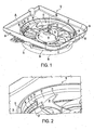
- FIG. 1 A fan-shroud structure, generally indicated at 10, is shown in FIG. 1 in accordance with the principles of the invention.
- the fan-shroud structure 10 includes a fan, generally indicated at 12, having a hub 14 coupled with a shaft 16 of a motor 18 for rotation of the fan 12 about axis B.
- the fan includes a plurality of blades 20.
- Each blade 20 is coupled to the hub 14 at one end thereof and the tip 21 of each blade 20 is coupled to an annular band 22.
- the band 22 is preferably L-shaped, having a radially extending portion 24 and an axially extending portion 27.
- the motor 18 is mounted to a shroud, generally indicated at 26.
- the shroud 26 includes support ribs 29 that extend from body 34 of the shroud 26 to a motor mount portion 19 of the shroud.
- the ribs 29 are generally adjacent to the blades 20 of the fan 12.
- the shroud 26 includes an improved labyrinth seal 28 having a corrugated profile.
- the seal 28 is preferably molded as an integral part of the shroud 26.
- the seal 28 can be molded as a separate part and assembled with the shroud 26 in a second operation.
- the corrugated profile of seal 28 can be of V-shape or polygonal shape with constant or variable spacing.
- the V-shaped profile is saw-toothed, including alternating peaks 35 and valleys 37. The peaks 35 are evenly spaced and the valleys 37 are also evenly spaced. As shown in FIG.
- seal 28' shows that certain or all peaks or valleys can include a radius without departing from the principles of the invention.
- FIG. 3b shows an uneven spacing of the polygonal shaped seal 28".
- the seal 28 is annular and generally adjacent to the band 22 to define a gap 30 ( FIG. 2 ) between the seal 28 and the band 22.
- the seal 28 thus provides resistance to air flow as air swirls and flows back into a gap 30, and minimizes air leakage across the gap 30.
- the swirl and axial components of air velocity now have to travel past the corrugations that dissipate the kinetic energy of the re-circulating air flow, thus reducing fan noise and increasing efficiency.
- the structure of the seal 28 also minimizes the size of the gap 30 and increases the air resistance in the gap 30 to minimize axial leakage flow.
- the shroud 26 includes an inlet nozzle, generally indicated at 32.
- the inlet nozzle 32 is preferably molded as an integral part of the shroud 26 and is embossed and surrounds the band 22 and the seal 28 at a front portion of the shroud 26.
- the inlet nozzle 32 has an inner diameter greater than an outer diameter of the annular band 22 and extends upwardly from base 34 of the shroud 26.
- the inlet nozzle 32 can be molded as an integral part together with the corrugated seal 28 and the shroud 26.
- the inlet nozzle 32 also significantly increases the stiffness of the shroud 26.
- the shroud 26 includes an outlet diffuser 36 that is preferably molded as a single piece with the shroud 26, the inlet 32 and the seal 28 by using moving slides in a mold.
- the outlet diffuser can be molded separately and assembled on the shroud in a second operation.
- the outlet diffuser 36 is thus a generally annular member surrounding the band 22 and seal 28 and extends outwardly from a rear portion of the shroud 26. Since the outlet diffuser 36 functions to diffuse air, a diameter of the diffuser 38 near the ribs 29 is less than the outermost diameter 40.
- the labyrinth seal 28 is provided by molding the shroud 26 to have the motor mount structure 19 disposed about an axis B, with the ribs 29 disposed in spaced relation and extending radially with respect to the axis. Each rib 29 has one end coupled to the motor mount structure and another end coupled to an annular ring 31.
- the labyrinth seal 28 of corrugated profile is molded integrally with the shroud 26 to be concentric with the annular ring 31 and to be axially spaced from and generally adjacent to the annular ring 31.
- the inlet nozzle 32 is molded, integrally with the one side of the shroud 26.
- the inlet nozzle 32 is concentric with the annular ring 31 and is axially spaced from the seal 28.
- the outlet diffuser 36 is molded, integrally with a side of the shroud opposite the one side thereof.
- the outlet diffuser 32 is concentric with and axially spaced from the annular ring 31.
- seal 28 is molded integrally with the shroud, difficulty in manufacturing of the seal is reduced and tolerances can be controlled more easily.
Landscapes
- Engineering & Computer Science (AREA)
- Mechanical Engineering (AREA)
- General Engineering & Computer Science (AREA)
- Structures Of Non-Positive Displacement Pumps (AREA)
Claims (16)
- Structure de déflecteur de ventilateur (10) comprenant :- un ventilateur (12) monté de manière à tourner autour d'un axe (B), le ventilateur (12) ayant une pluralité de pales (20), les extrémités (21) des pales (20) étant couplées avec une bande annulaire (22), et- un déflecteur (26) contenant un joint-labyrinthe (56) annulaire disposé généralement de manière adjacente à la bande annulaire (22), définissant ainsi un interstice (30) entre la bande annulaire (22) et le joint (28), le joint (28) ayant un profilé ondulé et étant construit et conçu pour fournir une résistance au flux d'air quand l'air tourbillonne et reflue dans l'interstice (30) et pour diminuer la fuite d'air à travers l'interstice (30),caractérisé par le fait que le profilé ondulé du joint-labyrinthe (28) est généralement en forme de V ayant des crêtes (35) et des creux (37) alternés.
- Structure de déflecteur de ventilateur (10) selon la revendication 1, dans laquelle les crêtes (35) sont espacées régulièrement et les creux (37) sont espacés régulièrement.
- Structure de déflecteur de ventilateur (10) selon la revendication 1, dans laquelle le profilé ondulé a une forme polygonale.
- Structure de déflecteur de ventilateur (10) selon la revendication 1, dans laquelle chacune des crêtes (35) et chacun des creux (37) contient une partie de rayon.
- Structure de déflecteur de ventilateur (10) selon la revendication 1, dans laquelle les crêtes (35) et les creux (37) alternés sont espacés régulièrement.
- Structure de déflecteur de ventilateur (10) selon la revendication 1, dans laquelle les crêtes (35) et les creux (37) alternés sont espacés irrégulièrement.
- Structure de déflecteur de ventilateur (10) selon la revendication 1, dans laquelle le joint-labyrinthe (28) est formé d'un seul tenant avec le déflecteur (26).
- Structure de déflecteur de ventilateur (10) selon la revendication 1, dans laquelle le déflecteur (26) comprend une buse d'entrée annulaire (32) entourant la bande (22) et le joint (28) et s'étendant vers l'extérieur au niveau d'une section avant du déflecteur (26).
- Structure de déflecteur de ventilateur (10) selon la revendication 8, dans laquelle la buse d'entrée (32) est formée d'un seul tenant avec le déflecteur (26) et a un diamètre intérieur supérieur à un diamètre extérieur de la bande annulaire (22).
- Structure de déflecteur de ventilateur (10) selon la revendication 1, dans laquelle le déflecteur (26) comprend un diffuseur de sortie (36) entourant la bande (22) et le joint (28) et s'étendant vers l'extérieur au niveau d'une section arrière du déflecteur (26).
- Structure de déflecteur de ventilateur (10) selon la revendication 10, dans laquelle le diffuseur de sortie (36) est formé d'un seul tenant avec le déflecteur (26).
- Structure de déflecteur de ventilateur (10) selon la revendication 1, dans laquelle le déflecteur (26) comprend une buse d'entrée annulaire (32) entourant la bande (22) et le joint (28) et s'étendant vers l'extérieur au niveau d'une section avant du déflecteur (26) et le déflecteur (26) comprend un diffuseur de sortie (36) entourant la bande (22) et le joint (28) et s'étendant vers l'extérieur au niveau d'une section arrière du déflecteur (26).
- Structure de déflecteur de ventilateur (10) selon la revendication 12, dans laquelle la buse d'entrée (32) et le diffuseur de sortie (36) sont formés d'un seul tenant avec le déflecteur (26).
- Procédé de fourniture d'un joint-labyrinthe (28) dans un déflecteur (26) d'une structure de déflecteur de ventilateur (10), le procédé comportant les étapes de :- moulage d'un déflecteur (26) pour avoir une structure de montage de moteur (19) disposée autour d'un axe (B), et des nervures (29) disposées dans une position espacée et s'étendant radialement par rapport à l'axe (B), chaque nervure (29) ayant une extrémité couplée avec la structure de moteur (19) et une autre extrémité couplée avec une bague annulaire (31), et- moulage, en un seul tenant avec le déflecteur (26), d'un joint-labyrinthe annulaire (28) de profilé ondulé, le joint (28) étant concentrique avec la bague annulaire (31) et étant axialement espacé de et généralement adjacent à la bague annulaire (31),caractérisé par le fait que l'étape de moulage du joint (28) comprend le moulage du profilé ondulé devant généralement être en forme de V et devant avoir des crêtes (35) et des creux (37) alternés.
- Procédé selon la revendication 14, comprenant en outre le moulage, en un seul tenant avec un côté du déflecteur (26), une buse d'entrée (32), la buse d'entrée (32) étant concentrique avec la bague annulaire (31) et étant axialement espacée du joint (28).
- Procédé selon la revendication 15, comprenant en outre le moulage, en un seul tenant avec un côté du déflecteur (26) faisant face à un côté de ce dernier, un diffuseur de sortie (36), le diffuseur de sortie (36) étant concentrique avec et axialement espacé de la bague annulaire (31).
Applications Claiming Priority (4)
| Application Number | Priority Date | Filing Date | Title |
|---|---|---|---|
| US44333403P | 2003-01-29 | 2003-01-29 | |
| US443334P | 2003-01-29 | ||
| US361721 | 2003-02-10 | ||
| US10/361,721 US6874990B2 (en) | 2003-01-29 | 2003-02-10 | Integral tip seal in a fan-shroud structure |
Publications (3)
| Publication Number | Publication Date |
|---|---|
| EP1443215A2 EP1443215A2 (fr) | 2004-08-04 |
| EP1443215A3 EP1443215A3 (fr) | 2005-03-16 |
| EP1443215B1 true EP1443215B1 (fr) | 2013-10-23 |
Family
ID=32658863
Family Applications (1)
| Application Number | Title | Priority Date | Filing Date |
|---|---|---|---|
| EP03079116.4A Expired - Lifetime EP1443215B1 (fr) | 2003-01-29 | 2003-12-18 | Etanchéification integrée pour buse de ventilateur |
Country Status (5)
| Country | Link |
|---|---|
| US (1) | US6874990B2 (fr) |
| EP (1) | EP1443215B1 (fr) |
| CN (1) | CN1534201A (fr) |
| ES (1) | ES2473791T3 (fr) |
| PT (1) | PT1443215E (fr) |
Cited By (1)
| Publication number | Priority date | Publication date | Assignee | Title |
|---|---|---|---|---|
| US9885368B2 (en) | 2012-05-24 | 2018-02-06 | Carrier Corporation | Stall margin enhancement of axial fan with rotating shroud |
Families Citing this family (34)
| Publication number | Priority date | Publication date | Assignee | Title |
|---|---|---|---|---|
| FR2879266B1 (fr) * | 2004-12-15 | 2007-02-02 | Valeo Systemes Dessuyage | Systeme de ventilateur comportant des moyens de limitation de debit d'air parasite |
| KR101155809B1 (ko) * | 2005-03-26 | 2012-06-12 | 한라공조주식회사 | 팬 및 쉬라우드 조립체 |
| US7416386B2 (en) * | 2005-09-21 | 2008-08-26 | Delta Electronics, Inc. | Heat dissipation apparatus |
| DE102006048483A1 (de) * | 2006-10-11 | 2008-05-08 | Behr Gmbh & Co. Kg | Axialgebläse und Verfahren zur Verhinderung einer Rezirkulationsströmung |
| US20100040458A1 (en) * | 2006-12-28 | 2010-02-18 | Carrier Corporation | Axial fan casing design with circumferentially spaced wedges |
| IT1399992B1 (it) * | 2010-05-11 | 2013-05-09 | Denso Thermal Systems Spa | Gruppo ventilatore per veicoli |
| US10639961B2 (en) * | 2010-07-07 | 2020-05-05 | Ford Global Technologies, Llc | Partial air inlet control strategy for air conditioning system |
| KR101724294B1 (ko) * | 2010-10-27 | 2017-04-07 | 엘지전자 주식회사 | 공기조화기의 실외기 |
| EP2458157B1 (fr) * | 2010-11-30 | 2015-10-14 | Techspace Aero S.A. | Abradable de virole intérieure de stator |
| JP5536236B2 (ja) * | 2011-01-11 | 2014-07-02 | 株式会社ミツバ | 電動ファン |
| ITTO20110362A1 (it) * | 2011-04-26 | 2012-10-27 | Denso Corp | Gruppo ventilatore per veicoli |
| US20120276836A1 (en) | 2011-04-29 | 2012-11-01 | Trane International Inc. | Blower Assembly |
| KR20130039481A (ko) * | 2011-10-12 | 2013-04-22 | 엘지전자 주식회사 | 축류팬 및 공기 조화기 |
| US9157362B2 (en) * | 2012-05-23 | 2015-10-13 | Denso International America, Inc. | Pressure release slot for fan noise improvement |
| CN103573717B (zh) * | 2012-07-24 | 2018-06-12 | 德昌电机(深圳)有限公司 | 风扇及其叶轮 |
| WO2014204224A1 (fr) * | 2013-06-19 | 2014-12-24 | 한라비스테온공조 주식회사 | Ensemble carénage de ventilateur |
| KR102120183B1 (ko) * | 2013-06-19 | 2020-06-08 | 한온시스템 주식회사 | 팬쉬라우드 조립체 |
| US10253676B2 (en) | 2013-12-20 | 2019-04-09 | Magna Powertrain Bad Homburg GmbH | Molded rotor for cooling fan motor |
| DE112015001218T5 (de) | 2014-03-13 | 2017-02-02 | Magna Electronics, Inc. | Fahrzeugkühllüfter mit aerodynamischen Statorstreben |
| CN103982466B (zh) * | 2014-04-23 | 2017-02-22 | 镇江市博林光电科技有限公司 | 大吸力轴流风机 |
| US10174481B2 (en) | 2014-08-26 | 2019-01-08 | Cnh Industrial America Llc | Shroud wear ring for a work vehicle |
| CN105799496B (zh) * | 2015-01-21 | 2019-10-18 | 翰昂汽车零部件有限公司 | 车辆用风扇护罩 |
| GB2545412B (en) * | 2015-12-11 | 2018-06-06 | Dyson Technology Ltd | A hair care appliance comprising a motor |
| KR101734722B1 (ko) * | 2015-12-14 | 2017-05-11 | 엘지전자 주식회사 | 공기 조화기의 오리피스 |
| JP2018096312A (ja) * | 2016-12-15 | 2018-06-21 | ダイキン工業株式会社 | 送風機、及び送風機を有する冷凍装置 |
| CN109114014A (zh) * | 2017-06-23 | 2019-01-01 | 博格华纳公司 | 具有用于降低再循环流量的集成风扇护罩通道的风扇系统 |
| JP6787860B2 (ja) * | 2017-09-14 | 2020-11-18 | 株式会社ミツバ | 送風装置 |
| US11142038B2 (en) | 2017-12-18 | 2021-10-12 | Carrier Corporation | Labyrinth seal for fan assembly |
| DE102019202116A1 (de) * | 2019-02-18 | 2020-08-20 | Brose Fahrzeugteile SE & Co. Kommanditgesellschaft, Würzburg | Kühlerlüfter eines Kraftfahrzeugs |
| US11573017B2 (en) | 2019-08-16 | 2023-02-07 | Airscape, Inc. | Ventilation system for a large industrial space |
| CN111255749B (zh) * | 2020-03-17 | 2025-05-27 | 特灵空调系统(中国)有限公司 | 导风圈和风机组件 |
| CN112762008B (zh) * | 2021-01-25 | 2025-01-07 | 珠海格力电器股份有限公司 | 风机装置及使用风机的电器 |
| CN114142679B (zh) * | 2021-11-24 | 2025-04-25 | 卧龙电气驱动集团股份有限公司 | 一种外转子电机的散热结构 |
| US11965517B1 (en) * | 2023-06-30 | 2024-04-23 | Brose Fahrzeugteile SE & Co. Kommanditgesellschaft, Würzburg | Cooling fan module |
Citations (1)
| Publication number | Priority date | Publication date | Assignee | Title |
|---|---|---|---|---|
| EP1340921A2 (fr) * | 2002-02-27 | 2003-09-03 | Halla Climate Control Corporation | Ensemble ventilateur |
Family Cites Families (19)
| Publication number | Priority date | Publication date | Assignee | Title |
|---|---|---|---|---|
| FR2051912A5 (fr) * | 1969-07-01 | 1971-04-09 | Rabouyt Denis | |
| US3814538A (en) * | 1972-08-21 | 1974-06-04 | Svenska Flaektfabriken Ab | Air inlet throat for fans |
| US3858644A (en) * | 1973-04-05 | 1975-01-07 | Int Harvester Co | Fan shroud exit structure |
| US3842902A (en) * | 1973-07-05 | 1974-10-22 | Hayes Albion Corp | Labyrinthian fan |
| US4311431A (en) * | 1978-11-08 | 1982-01-19 | Teledyne Industries, Inc. | Turbine engine with shroud cooling means |
| JPS59168300A (ja) * | 1983-03-14 | 1984-09-21 | Matsushita Electric Ind Co Ltd | 流体機械のエアガイダ−装置 |
| US4548548A (en) * | 1984-05-23 | 1985-10-22 | Airflow Research And Manufacturing Corp. | Fan and housing |
| US5489186A (en) | 1991-08-30 | 1996-02-06 | Airflow Research And Manufacturing Corp. | Housing with recirculation control for use with banded axial-flow fans |
| EP0601119B1 (fr) | 1991-08-30 | 1999-01-13 | AIRFLOW RESEARCH & MANUFACTURING CORP. | Ventilateur a biais vers l'avant, et a inclinaison et a cambrage dans le sens de la corde |
| US5244347A (en) * | 1991-10-11 | 1993-09-14 | Siemens Automotive Limited | High efficiency, low noise, axial flow fan |
| JPH09505375A (ja) * | 1993-08-30 | 1997-05-27 | エアフロー リサーチ マニュファクチュアリング コーポレーション | 帯付き軸流ファンと共に使用するための再循環制御を伴うハウジング |
| KR100467331B1 (ko) | 1997-06-05 | 2005-04-08 | 한라공조주식회사 | 휀과,휀쉬라우드조립체 |
| US5957661A (en) * | 1998-06-16 | 1999-09-28 | Siemens Canada Limited | High efficiency to diameter ratio and low weight axial flow fan |
| US6113347A (en) * | 1998-12-28 | 2000-09-05 | General Electric Company | Blade containment system |
| US6315521B1 (en) * | 1999-11-30 | 2001-11-13 | Siemens Automotive Inc. | Fan design with low acoustic tonal components |
| US6471472B1 (en) * | 2000-05-03 | 2002-10-29 | Siemens Canada Limited | Turbomachine shroud fibrous tip seal |
| TW562087U (en) * | 2000-06-16 | 2003-11-11 | Delta Electronics Inc | Frame structure for fan |
| DE60117177T2 (de) * | 2000-11-08 | 2006-09-28 | Robert Bosch Corp., Broadview | Hocheffizienter, zustromangepasster axiallüfter |
| US6508624B2 (en) * | 2001-05-02 | 2003-01-21 | Siemens Automotive, Inc. | Turbomachine with double-faced rotor-shroud seal structure |
-
2003
- 2003-02-10 US US10/361,721 patent/US6874990B2/en not_active Expired - Lifetime
- 2003-12-18 PT PT3079116T patent/PT1443215E/pt unknown
- 2003-12-18 EP EP03079116.4A patent/EP1443215B1/fr not_active Expired - Lifetime
- 2003-12-18 ES ES03079116.4T patent/ES2473791T3/es not_active Expired - Lifetime
-
2004
- 2004-01-29 CN CNA2004100035505A patent/CN1534201A/zh active Pending
Patent Citations (1)
| Publication number | Priority date | Publication date | Assignee | Title |
|---|---|---|---|---|
| EP1340921A2 (fr) * | 2002-02-27 | 2003-09-03 | Halla Climate Control Corporation | Ensemble ventilateur |
Cited By (1)
| Publication number | Priority date | Publication date | Assignee | Title |
|---|---|---|---|---|
| US9885368B2 (en) | 2012-05-24 | 2018-02-06 | Carrier Corporation | Stall margin enhancement of axial fan with rotating shroud |
Also Published As
| Publication number | Publication date |
|---|---|
| EP1443215A2 (fr) | 2004-08-04 |
| US6874990B2 (en) | 2005-04-05 |
| ES2473791T3 (es) | 2014-07-07 |
| US20040156712A1 (en) | 2004-08-12 |
| CN1534201A (zh) | 2004-10-06 |
| EP1443215A3 (fr) | 2005-03-16 |
| PT1443215E (pt) | 2014-01-29 |
Similar Documents
| Publication | Publication Date | Title |
|---|---|---|
| EP1443215B1 (fr) | Etanchéification integrée pour buse de ventilateur | |
| US5423660A (en) | Fan inlet with curved lip and cylindrical member forming labyrinth seal | |
| KR101228764B1 (ko) | 프로펠러 팬 | |
| KR100818429B1 (ko) | 고효율의 단일형 원심형 블로워 | |
| JP5466315B2 (ja) | ブロワアセンブリ | |
| US7789622B2 (en) | Engine cooling fan assembly | |
| CN209959503U (zh) | 对角风扇 | |
| EP1923572B1 (fr) | Ventilateur électrique pour nettoyeur électrique | |
| EP3462039B1 (fr) | Ventilateur électrique et aspirateur comprenant celui-ci | |
| KR20130143094A (ko) | 원형 유입부와 회전 비대칭 배출부를 가진 팬 디퓨저 | |
| CN101617127B (zh) | 风机叶轮、系统和传动装置结构系列 | |
| CN209743192U (zh) | 斜流风机 | |
| CN101617128B (zh) | 风机叶轮、系统和传动装置结构系列 | |
| EP2097313B1 (fr) | Conception de carter de ventilateur axial avec coins périphériquement espacés | |
| JP2011202560A (ja) | 電動送風機とそれを用いた電気掃除機 | |
| WO2015094940A1 (fr) | Ensemble soufflante comprenant une turbine à atténuation de bruit | |
| KR20200090095A (ko) | 차량용 축 방향 팬 배열체 | |
| CN117120727A (zh) | 带有冷却组件的电马达 | |
| WO2008082428A1 (fr) | Pertes d'espace d'extrémité réduites sur ventilateurs hélicoïdaux | |
| US20060093479A1 (en) | Pressure-boosting axial-flow heat-dissipating fan | |
| CN100371610C (zh) | 散热装置 | |
| CN210033892U (zh) | 对角风扇 | |
| CN223215465U (zh) | 叶轮和风扇组件 | |
| US20250163929A1 (en) | Method for the production of a shielded impeller, shielded impeller and fan | |
| JP2025534457A (ja) | ファンおよびファン用冷却構造 |
Legal Events
| Date | Code | Title | Description |
|---|---|---|---|
| PUAI | Public reference made under article 153(3) epc to a published international application that has entered the european phase |
Free format text: ORIGINAL CODE: 0009012 |
|
| 17P | Request for examination filed |
Effective date: 20040308 |
|
| AK | Designated contracting states |
Kind code of ref document: A2 Designated state(s): AT BE BG CH CY CZ DE DK EE ES FI FR GB GR HU IE IT LI LU MC NL PT RO SE SI SK TR |
|
| AX | Request for extension of the european patent |
Extension state: AL LT LV MK |
|
| PUAL | Search report despatched |
Free format text: ORIGINAL CODE: 0009013 |
|
| AK | Designated contracting states |
Kind code of ref document: A3 Designated state(s): AT BE BG CH CY CZ DE DK EE ES FI FR GB GR HU IE IT LI LU MC NL PT RO SE SI SK TR |
|
| AX | Request for extension of the european patent |
Extension state: AL LT LV MK |
|
| AKX | Designation fees paid |
Designated state(s): AT BE BG CH CY CZ DE DK EE ES FI FR GB GR HU IE IT LI LU MC NL PT RO SE SI SK TR |
|
| 17Q | First examination report despatched |
Effective date: 20071227 |
|
| RAP1 | Party data changed (applicant data changed or rights of an application transferred) |
Owner name: BROSE FAHRZEUGTEILE GMBH & CO. KOMMANDITGESELLSCHA |
|
| GRAP | Despatch of communication of intention to grant a patent |
Free format text: ORIGINAL CODE: EPIDOSNIGR1 |
|
| INTG | Intention to grant announced |
Effective date: 20130614 |
|
| GRAS | Grant fee paid |
Free format text: ORIGINAL CODE: EPIDOSNIGR3 |
|
| GRAA | (expected) grant |
Free format text: ORIGINAL CODE: 0009210 |
|
| AK | Designated contracting states |
Kind code of ref document: B1 Designated state(s): AT BE BG CH CY CZ DE DK EE ES FI FR GB GR HU IE IT LI LU MC NL PT RO SE SI SK TR |
|
| REG | Reference to a national code |
Ref country code: GB Ref legal event code: FG4D |
|
| REG | Reference to a national code |
Ref country code: DE Ref legal event code: R082 Ref document number: 60345126 Country of ref document: DE |
|
| REG | Reference to a national code |
Ref country code: CH Ref legal event code: EP |
|
| REG | Reference to a national code |
Ref country code: AT Ref legal event code: REF Ref document number: 637769 Country of ref document: AT Kind code of ref document: T Effective date: 20131115 |
|
| REG | Reference to a national code |
Ref country code: IE Ref legal event code: FG4D |
|
| REG | Reference to a national code |
Ref country code: DE Ref legal event code: R096 Ref document number: 60345126 Country of ref document: DE Effective date: 20131212 |
|
| REG | Reference to a national code |
Ref country code: PT Ref legal event code: SC4A Free format text: AVAILABILITY OF NATIONAL TRANSLATION Effective date: 20140120 |
|
| REG | Reference to a national code |
Ref country code: NL Ref legal event code: VDEP Effective date: 20131023 |
|
| REG | Reference to a national code |
Ref country code: AT Ref legal event code: MK05 Ref document number: 637769 Country of ref document: AT Kind code of ref document: T Effective date: 20131023 |
|
| PG25 | Lapsed in a contracting state [announced via postgrant information from national office to epo] |
Ref country code: FI Free format text: LAPSE BECAUSE OF FAILURE TO SUBMIT A TRANSLATION OF THE DESCRIPTION OR TO PAY THE FEE WITHIN THE PRESCRIBED TIME-LIMIT Effective date: 20131023 Ref country code: NL Free format text: LAPSE BECAUSE OF FAILURE TO SUBMIT A TRANSLATION OF THE DESCRIPTION OR TO PAY THE FEE WITHIN THE PRESCRIBED TIME-LIMIT Effective date: 20131023 Ref country code: SE Free format text: LAPSE BECAUSE OF FAILURE TO SUBMIT A TRANSLATION OF THE DESCRIPTION OR TO PAY THE FEE WITHIN THE PRESCRIBED TIME-LIMIT Effective date: 20131023 Ref country code: BE Free format text: LAPSE BECAUSE OF FAILURE TO SUBMIT A TRANSLATION OF THE DESCRIPTION OR TO PAY THE FEE WITHIN THE PRESCRIBED TIME-LIMIT Effective date: 20131023 |
|
| REG | Reference to a national code |
Ref country code: SK Ref legal event code: T3 Ref document number: E 15775 Country of ref document: SK |
|
| PG25 | Lapsed in a contracting state [announced via postgrant information from national office to epo] |
Ref country code: AT Free format text: LAPSE BECAUSE OF FAILURE TO SUBMIT A TRANSLATION OF THE DESCRIPTION OR TO PAY THE FEE WITHIN THE PRESCRIBED TIME-LIMIT Effective date: 20131023 Ref country code: CY Free format text: LAPSE BECAUSE OF FAILURE TO SUBMIT A TRANSLATION OF THE DESCRIPTION OR TO PAY THE FEE WITHIN THE PRESCRIBED TIME-LIMIT Effective date: 20131023 |
|
| REG | Reference to a national code |
Ref country code: ES Ref legal event code: FG2A Ref document number: 2473791 Country of ref document: ES Kind code of ref document: T3 Effective date: 20140707 |
|
| REG | Reference to a national code |
Ref country code: DE Ref legal event code: R097 Ref document number: 60345126 Country of ref document: DE |
|
| PG25 | Lapsed in a contracting state [announced via postgrant information from national office to epo] |
Ref country code: EE Free format text: LAPSE BECAUSE OF FAILURE TO SUBMIT A TRANSLATION OF THE DESCRIPTION OR TO PAY THE FEE WITHIN THE PRESCRIBED TIME-LIMIT Effective date: 20131023 |
|
| REG | Reference to a national code |
Ref country code: CH Ref legal event code: PL |
|
| REG | Reference to a national code |
Ref country code: HU Ref legal event code: AG4A Ref document number: E020140 Country of ref document: HU |
|
| PG25 | Lapsed in a contracting state [announced via postgrant information from national office to epo] |
Ref country code: RO Free format text: LAPSE BECAUSE OF FAILURE TO SUBMIT A TRANSLATION OF THE DESCRIPTION OR TO PAY THE FEE WITHIN THE PRESCRIBED TIME-LIMIT Effective date: 20131023 Ref country code: MC Free format text: LAPSE BECAUSE OF FAILURE TO SUBMIT A TRANSLATION OF THE DESCRIPTION OR TO PAY THE FEE WITHIN THE PRESCRIBED TIME-LIMIT Effective date: 20131023 Ref country code: LU Free format text: LAPSE BECAUSE OF FAILURE TO SUBMIT A TRANSLATION OF THE DESCRIPTION OR TO PAY THE FEE WITHIN THE PRESCRIBED TIME-LIMIT Effective date: 20131218 |
|
| PLBE | No opposition filed within time limit |
Free format text: ORIGINAL CODE: 0009261 |
|
| STAA | Information on the status of an ep patent application or granted ep patent |
Free format text: STATUS: NO OPPOSITION FILED WITHIN TIME LIMIT |
|
| REG | Reference to a national code |
Ref country code: IE Ref legal event code: MM4A |
|
| PG25 | Lapsed in a contracting state [announced via postgrant information from national office to epo] |
Ref country code: DK Free format text: LAPSE BECAUSE OF FAILURE TO SUBMIT A TRANSLATION OF THE DESCRIPTION OR TO PAY THE FEE WITHIN THE PRESCRIBED TIME-LIMIT Effective date: 20131023 |
|
| 26N | No opposition filed |
Effective date: 20140724 |
|
| PG25 | Lapsed in a contracting state [announced via postgrant information from national office to epo] |
Ref country code: CH Free format text: LAPSE BECAUSE OF NON-PAYMENT OF DUE FEES Effective date: 20131231 Ref country code: LI Free format text: LAPSE BECAUSE OF NON-PAYMENT OF DUE FEES Effective date: 20131231 Ref country code: IE Free format text: LAPSE BECAUSE OF NON-PAYMENT OF DUE FEES Effective date: 20131218 |
|
| REG | Reference to a national code |
Ref country code: DE Ref legal event code: R097 Ref document number: 60345126 Country of ref document: DE Effective date: 20140724 |
|
| PG25 | Lapsed in a contracting state [announced via postgrant information from national office to epo] |
Ref country code: SI Free format text: LAPSE BECAUSE OF FAILURE TO SUBMIT A TRANSLATION OF THE DESCRIPTION OR TO PAY THE FEE WITHIN THE PRESCRIBED TIME-LIMIT Effective date: 20131023 |
|
| PG25 | Lapsed in a contracting state [announced via postgrant information from national office to epo] |
Ref country code: BG Free format text: LAPSE BECAUSE OF FAILURE TO SUBMIT A TRANSLATION OF THE DESCRIPTION OR TO PAY THE FEE WITHIN THE PRESCRIBED TIME-LIMIT Effective date: 20131023 |
|
| PG25 | Lapsed in a contracting state [announced via postgrant information from national office to epo] |
Ref country code: GR Free format text: LAPSE BECAUSE OF NON-PAYMENT OF DUE FEES Effective date: 20131023 |
|
| REG | Reference to a national code |
Ref country code: FR Ref legal event code: PLFP Year of fee payment: 13 |
|
| PG25 | Lapsed in a contracting state [announced via postgrant information from national office to epo] |
Ref country code: GR Free format text: LAPSE BECAUSE OF FAILURE TO SUBMIT A TRANSLATION OF THE DESCRIPTION OR TO PAY THE FEE WITHIN THE PRESCRIBED TIME-LIMIT Effective date: 20140124 |
|
| REG | Reference to a national code |
Ref country code: FR Ref legal event code: PLFP Year of fee payment: 14 |
|
| REG | Reference to a national code |
Ref country code: FR Ref legal event code: PLFP Year of fee payment: 15 |
|
| REG | Reference to a national code |
Ref country code: DE Ref legal event code: R081 Ref document number: 60345126 Country of ref document: DE Owner name: BROSE FAHRZEUGTEILE SE & CO. KOMMANDITGESELLSC, DE Free format text: FORMER OWNER: BROSE FAHRZEUGTEILE GMBH & CO. KOMMANDITGESELLSCHAFT, WUERZBURG, 97076 WUERZBURG, DE |
|
| PGFP | Annual fee paid to national office [announced via postgrant information from national office to epo] |
Ref country code: SK Payment date: 20221115 Year of fee payment: 20 Ref country code: IT Payment date: 20221111 Year of fee payment: 20 Ref country code: GB Payment date: 20221103 Year of fee payment: 20 Ref country code: FR Payment date: 20221110 Year of fee payment: 20 Ref country code: DE Payment date: 20221231 Year of fee payment: 20 Ref country code: CZ Payment date: 20221206 Year of fee payment: 20 |
|
| PGFP | Annual fee paid to national office [announced via postgrant information from national office to epo] |
Ref country code: PT Payment date: 20221219 Year of fee payment: 20 Ref country code: HU Payment date: 20221126 Year of fee payment: 20 |
|
| PGFP | Annual fee paid to national office [announced via postgrant information from national office to epo] |
Ref country code: TR Payment date: 20221216 Year of fee payment: 20 Ref country code: ES Payment date: 20230110 Year of fee payment: 20 |
|
| REG | Reference to a national code |
Ref country code: DE Ref legal event code: R071 Ref document number: 60345126 Country of ref document: DE |
|
| REG | Reference to a national code |
Ref country code: ES Ref legal event code: FD2A Effective date: 20240102 |
|
| REG | Reference to a national code |
Ref country code: GB Ref legal event code: PE20 Expiry date: 20231217 Ref country code: SK Ref legal event code: MK4A Ref document number: E 15775 Country of ref document: SK Expiry date: 20231218 |
|
| PG25 | Lapsed in a contracting state [announced via postgrant information from national office to epo] |
Ref country code: SK Free format text: LAPSE BECAUSE OF EXPIRATION OF PROTECTION Effective date: 20231218 |
|
| PG25 | Lapsed in a contracting state [announced via postgrant information from national office to epo] |
Ref country code: GB Free format text: LAPSE BECAUSE OF EXPIRATION OF PROTECTION Effective date: 20231217 |
|
| PG25 | Lapsed in a contracting state [announced via postgrant information from national office to epo] |
Ref country code: ES Free format text: LAPSE BECAUSE OF EXPIRATION OF PROTECTION Effective date: 20231219 |
|
| PG25 | Lapsed in a contracting state [announced via postgrant information from national office to epo] |
Ref country code: SK Free format text: LAPSE BECAUSE OF EXPIRATION OF PROTECTION Effective date: 20231218 Ref country code: GB Free format text: LAPSE BECAUSE OF EXPIRATION OF PROTECTION Effective date: 20231217 Ref country code: ES Free format text: LAPSE BECAUSE OF EXPIRATION OF PROTECTION Effective date: 20231219 Ref country code: CZ Free format text: LAPSE BECAUSE OF EXPIRATION OF PROTECTION Effective date: 20231218 |
|
| PG25 | Lapsed in a contracting state [announced via postgrant information from national office to epo] |
Ref country code: PT Free format text: LAPSE BECAUSE OF EXPIRATION OF PROTECTION Effective date: 20240102 |