EP1443233A1 - Reibungskupplung - Google Patents
Reibungskupplung Download PDFInfo
- Publication number
- EP1443233A1 EP1443233A1 EP04002150A EP04002150A EP1443233A1 EP 1443233 A1 EP1443233 A1 EP 1443233A1 EP 04002150 A EP04002150 A EP 04002150A EP 04002150 A EP04002150 A EP 04002150A EP 1443233 A1 EP1443233 A1 EP 1443233A1
- Authority
- EP
- European Patent Office
- Prior art keywords
- housing
- friction clutch
- clutch according
- force
- assembly
- Prior art date
- Legal status (The legal status is an assumption and is not a legal conclusion. Google has not performed a legal analysis and makes no representation as to the accuracy of the status listed.)
- Granted
Links
Images


Classifications
-
- F—MECHANICAL ENGINEERING; LIGHTING; HEATING; WEAPONS; BLASTING
- F16—ENGINEERING ELEMENTS AND UNITS; GENERAL MEASURES FOR PRODUCING AND MAINTAINING EFFECTIVE FUNCTIONING OF MACHINES OR INSTALLATIONS; THERMAL INSULATION IN GENERAL
- F16D—COUPLINGS FOR TRANSMITTING ROTATION; CLUTCHES; BRAKES
- F16D21/00—Systems comprising a plurality of actuated clutches
- F16D21/02—Systems comprising a plurality of actuated clutches for interconnecting three or more shafts or other transmission members in different ways
- F16D21/06—Systems comprising a plurality of actuated clutches for interconnecting three or more shafts or other transmission members in different ways at least two driving shafts or two driven shafts being concentric
-
- F—MECHANICAL ENGINEERING; LIGHTING; HEATING; WEAPONS; BLASTING
- F16—ENGINEERING ELEMENTS AND UNITS; GENERAL MEASURES FOR PRODUCING AND MAINTAINING EFFECTIVE FUNCTIONING OF MACHINES OR INSTALLATIONS; THERMAL INSULATION IN GENERAL
- F16D—COUPLINGS FOR TRANSMITTING ROTATION; CLUTCHES; BRAKES
- F16D13/00—Friction clutches
- F16D13/58—Details
- F16D13/583—Diaphragm-springs, e.g. Belleville
- F16D13/585—Arrangements or details relating to the mounting or support of the diaphragm on the clutch on the clutch cover or the pressure plate
-
- F—MECHANICAL ENGINEERING; LIGHTING; HEATING; WEAPONS; BLASTING
- F16—ENGINEERING ELEMENTS AND UNITS; GENERAL MEASURES FOR PRODUCING AND MAINTAINING EFFECTIVE FUNCTIONING OF MACHINES OR INSTALLATIONS; THERMAL INSULATION IN GENERAL
- F16D—COUPLINGS FOR TRANSMITTING ROTATION; CLUTCHES; BRAKES
- F16D21/00—Systems comprising a plurality of actuated clutches
- F16D21/02—Systems comprising a plurality of actuated clutches for interconnecting three or more shafts or other transmission members in different ways
- F16D21/06—Systems comprising a plurality of actuated clutches for interconnecting three or more shafts or other transmission members in different ways at least two driving shafts or two driven shafts being concentric
- F16D2021/0607—Double clutch with torque input plate in-between the two clutches, i.e. having a central input plate
-
- F—MECHANICAL ENGINEERING; LIGHTING; HEATING; WEAPONS; BLASTING
- F16—ENGINEERING ELEMENTS AND UNITS; GENERAL MEASURES FOR PRODUCING AND MAINTAINING EFFECTIVE FUNCTIONING OF MACHINES OR INSTALLATIONS; THERMAL INSULATION IN GENERAL
- F16D—COUPLINGS FOR TRANSMITTING ROTATION; CLUTCHES; BRAKES
- F16D21/00—Systems comprising a plurality of actuated clutches
- F16D21/02—Systems comprising a plurality of actuated clutches for interconnecting three or more shafts or other transmission members in different ways
- F16D21/06—Systems comprising a plurality of actuated clutches for interconnecting three or more shafts or other transmission members in different ways at least two driving shafts or two driven shafts being concentric
- F16D2021/0684—Mechanically actuated clutches with two clutch plates
Definitions
- the present invention relates to a friction clutch, which a Housing assembly, a pressure plate, which with the housing assembly for common rotation about a rotation axis and in the direction of the rotation axis is coupled with respect to this displaceable, a Einschersystem for Generation of an engagement force and a Kraftbeetzungsan extract to Transmission of the engagement force has on the pressure plate.
- a friction clutch comprising a housing assembly, a pressure plate, which with the housing assembly for common rotation around a Rotary axis and in the direction of the axis of rotation with respect to this displaced coupled, an engagement system for generating an engagement force and a Kraftbeaufschlagungsanowski extract for transmitting the engagement force on the pressure plate, wherein the Kraftbeaufschlagungsan ever biased is one of the engaging force acting at the beginning of an engagement to provide counteracting reaction force.
- the Kraftbeetzleyungsan extract either in its radially outer edge region with respect to the housing arrangement and in a radially inner area with respect to the pressure plate be supported, or in its radially outer edge region with respect to the pressure plate and in a radially further inward Be supported area relative to the housing assembly, wherein the respective Support point with respect to the housing assembly as a fulcrum or Rotary bearing of Kraftbeaufschlagungsan ever serves.
- the bias of Kraftbeaufschlagungsan be achieved by a diaphragm spring with one of the Hardening position (manufacturing) deviating mounting position is used, i.e. the diaphragm spring before, during or after installation in the For example, clutches of the normal-open type via accordingly trained stops is clamped in the clutch housing so that they provides the desired reaction force.
- the support in a first axial Direction over a at a bottom portion of the housing ab bases first support element takes place.
- the support in the second axial direction can for example be integrally provided on the housing, carried out by forming the housing support areas.
- the support in one second axial direction via an axially fixedly connected to the housing second support element takes place.
- This second support element can, for example with the housing by positive locking, by material connection, in particular welding, or using fasteners, such as. Rivet bolt, bolt or the like, done.
- the housing comprises a first housing component, on which the support in a first axial direction, and a second housing member includes, on which the support in a second axial direction he follows.
- the first housing component on the second housing component be worn or the two housing components, for example, over common fasteners to a common carrier fixed be worn.
- the bias of Kraftbeaufschlagungsan For example, be achieved by the Kraftbeaufschlagungsanowskiowski as well as the coupling housing is, i. that the Kraftbeaufschlagungsan immediately following the desired reaction force.
- the Vorspannanschlagan inch from Einschersystem is formed, that is, the bias state by the system of Kraftbeaufschlagungsanowski inch on the clutch housing and the engagement system is reached, or that the Vorspannanschlagan whatsoever to the Housing arrangement is provided, that is, that the bias state by the plant of Kraftbeaufschlagungsanowski at least two from each other spaced areas of the coupling housing is achieved.
- Vorspannanschlagan instrument a radially outer edge region of the Kraftbeaufschlagungsanowski herein supported, the support, for example, via material protrusions can be done on the housing or so-called wire rings, which as supports or stops for the Kraftbeetzhausungsaniser serve.
- Vorspannanschlagan in one opposite the outer edge region of the Kraftbeaufschlagungsanowski immediately adjacent the outer edge region of the Kraftbeaufschlagungsanowski immediately adjacent the outer edge region of the Kraftbeaufschlagungsanowski immediately adjacent the Housing provided wire rings conceivable, with additional biasing elements be provided for example in the form of clamping bolts can to bias the Kraftbeaufschlagungsan ever.
- the support takes place within the range in which the pressure plate on the Kraftbeierschlagungsanix is supported.
- the Kraftbeaufschlagungsan Aunt at least one diaphragm spring element comprises and / or that the Kraftbeaufschlagungsan Aunt comprises a plurality of lever elements, which in Direction of disengagement are biased, wherein the lever elements biasing elements can be assigned, which the lever elements in Pretend direction to disengage.
- the friction clutch is a double clutch with two coupling regions, the Kraftbeaufschlagungsan extract in the one coupling region in its radially outer Edge region with respect to the housing assembly and in a radially further inside area relative to the pressure plate is supported and wherein the Kraftbeaufschlagungsan extract in the other coupling region in its radially outer edge region with respect to the pressure plate and in a radially inner region with respect to the housing assembly is supported.
- the present invention relates to a A friction clutch comprising a housing assembly, a pressure plate, which with the housing assembly for common rotation around a Rotary axis and in the direction of the axis of rotation with respect to this displaced coupled, an engagement system for generating an engagement force, a Kraftbeaufschlagungsanowski extract for transmitting the engagement force on the Pressure plate, wherein the Kraftbeaufschlagungsan extract in their radial outer edge region with respect to the housing assembly and in a radial further inside area is supported with respect to the pressure plate, and wherein the Kraftbeaufschlagungsan extract with respect to the housing assembly is supported in both axial directions.
- friction clutch can be combined with all previously described feature groups, either individually or in Combination, in particular those groups of characteristics that are based on the two-sided axial support of Kraftbeetzschungsan expect on Refer to housing.
- Fig. 1 shows a in a drive train between a drive unit and a transmission arranged double clutch 10.
- the double clutch 10 essentially comprises two coupling regions 12, 14, through which optionally a torque from a drive shaft, such as crankshaft an internal combustion engine, on one of two coaxial with each other arranged transmission input shafts can be transmitted.
- a drive shaft such as crankshaft an internal combustion engine
- the dual clutch 10 has a generally designated 16 and on several parts composite housing assembly.
- a plate member 20 is in a radially outer, substantially axial extending portion 22 via a plurality of bolts 24th attached to the disc-like part 18. With a radially inward cross-annular portion 26 (hereinafter referred to as abutment plate 26th referred to) forms the plate member 20 for the two in more detail below explained coupling portions 12, 14 of the dual clutch 10 a Abutment area.
- a housing part 28 is with its radially outer, itself also substantially axially extending portion 30 by means of a Plurality of bolts 32 with the plate member 20 firmly connected.
- a radially inwardly engaging annular portion or bottom portion 34th the housing part 28 serves to support or pivotal mounting on a Transmission housing o. The like. Via a bearing 36th
- the first coupling region 12 of the double clutch 10 comprises a pressure plate 38, which is arranged on one axial side of the abutment plate 26 is. Between this pressure plate 38 and the abutment plate 26 is located friction linings 40, 42 comprising friction surface arrangement 44 of a clutch disc 46 of the first coupling portion 12.
- the clutch disc 46 with a torsional vibration damper 48 trained.
- the clutch disc 46 In its radially inner region is the clutch disc 46 via a hub 50 thereof for non-rotatable coupling a first drive shaft or transmission input shaft, not shown educated.
- the power transmission assembly 52 includes two pot or cup-shaped power transmission elements 60, 62, which bridge the abutment plate 26 and in its radially outer region connected to each other.
- the power transmission element 60 may be the Pressure plate 38 with intermediate storage of a wear adjustment device, not shown apply.
- the force element 54 is in its radially outer region 64 on the power transmission element 62 supported and is in its radially further inward Area 66 via a wire ring 68 o. The like.
- the force element 54 may be formed, for example, as a diaphragm spring However, for example, a power transmission lever assembly with comprise a plurality of circumferentially distributed lever elements.
- the second coupling portion 14 comprises on the other axial side of the Abutment plate 26 also has a pressure plate 72 which is connected to the abutment plate 26, for example, again by tangential leaf springs o. The like., which can also generate a release force, rotationally fixed, but in the direction of Axis A is movably connected.
- a clutch disc 76 of the second coupling portion 14 Between pressure plate 72 and the Abutment plate 26 is the friction surface 74 of a clutch disc 76 of the second coupling portion 14 with their friction linings 78, 80.
- the clutch disc 76 has in the illustrated embodiment a torsional vibration damper 82. In her radially inner Area is the clutch disc 76 via a hub 84 for rotationally fixed Coupling to a first (not shown) transmission input shaft in Essentially concentrically arranged second (not shown) transmission input shaft educated.
- a force applying element 86 of the second coupling portion 14 is in its radially outer region 88 via a wire ring 90 o.
- the like At the Supported inside the housing part 28 and can continue in its radially inside area 92 act on the pressure plate 72.
- At the radial inner end 94 of Kraftbeaufyerungselements 86 is an operating area the second actuator 96 of the actuating mechanism 58 to be charged.
- the Kraftbeaufleyungselement 84 may be formed as a diaphragm spring or as a lever assembly.
- the illustrated dual clutch assembly 10 is of the normal open type. This type of clutch is used in contrast to normal-closed type clutches the two actuators 56, 96 of the actuating mechanism 58 to it, by an admission of the different Kraftbeaufschlagungs institute 54, 86 each generate an engaging force, with which the pressure plates 38 and 72 for engaging the respective Clutch area are pressed in the direction of the abutment plate 26, whereas the restoring force for the actuating mechanism 58, i.e. the force necessary to open the clutch, from the clutch itself must be applied.
- the Kraftbeaufyerungsetti 54, 86 of the clutch of the normal-open type however, designed so that they work at the lowest possible force level.
- the restoring force is therefore mainly of generates the tangential leaf springs or pad springs, not shown, which are designed so that the restoring forces when open Just enough clutch to keep the clutch securely open. Accordingly, the starting level of the engagement force is very low, which is problematic, because such systems running in the front the Eingurumble are difficult to control, because there are small force changes at the low level in the engagement system already to large path changes at the respective engagement bearing 98, 100 of the respective actuating element 56, 96 lead.
- the bias of Kraftbeetzschlagungselements 86 is in this embodiment, either by the Appendix the Kraftbeetzleyungselements 86 on the inside of the after radially inwardly annular ring-like portion 34 of the housing part 28 and the system of the radially inner end 94 of the Kraftbeaufschlagungselements 86 generates the engagement bearing 100, which each have the force application element in the direction away from the actuating mechanism 58.
- the force-applying element 54 of the first coupling portion 12 is a radially inwardly engaging Section 34 of the housing part 28, for example by riveting fixed spacer pin 106, which has an opening 107 of the Kraftbeaufschlagungselements 54 passes through and one on the head 109 of the Distance bolt 106 adjacent wire ring 108 lifting the Kraftbeaufschlagungselements 54 of the acting as a fulcrum wire ring 68 prevented.
- the housing part 28 in its, the radially outer portion 64 of the Kraftbeaufschlagungselements 54 near range, i.
- the preload described above the Kraftbeaufschlagungs institute in the form of a diaphragm spring and the measures to prevent the lifting of Kraftbeaufschlagungs institute 54, 86 of their respective pivots can also be used in a single clutch.
- the embodiment of the invention also in friction clutches be used, which an additional, on the respective Kraftbeaufschlagungselement for example, attacking counter-force generating element in the form of a between the radially inwardly cross-ring-like Section 34 of the housing part 28 and the respective Kraftbeaufschlagungselement 54 and 86 provided (not shown) counter-force generating element, for example in the form of an additional spring.
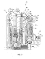
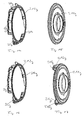
- FIG. 2 A modification of the friction clutch arrangement described in FIG is shown in Fig. 2, wherein components, those of the first embodiment correspond, with the same reference numerals, respectively increased around the letter "a”, are provided. It will only be below on the differences, so that the description the first embodiment is referenced.
- This second embodiment differs from the embodiment of the Fig. 1 essentially in that the fixation of radially outer portion 88a of the loading member 86a of the second coupling portion 14a in both axial directions only by the fulcrum wire ring 90a and a tab 102a takes place, which at the substantially axially extending portion 30a of the housing part 28a is formed, omitting the wire ring 104. Furthermore, in this embodiment, the radially inward cross-annular portion 34a of the housing part 28 in the region of Pressure plate 72a projecting in the direction of the pressure plate 72a out Bead 112a, through which the force-applying element 86a in Mounting position is held or biased.
- a bead 114a which replaces the wire ring 68 of the first embodiment, which is a axially shorter design allows.
- the housing arrangement points 28a in this embodiment in its transition region from the The substantially axially extending portion 30 a to the after radially inwardly extending annular portion 34 a does not increase Area 110, as in the first embodiment, but a wire ring 116a, which the force-applying element 54a in the installed position holds.
- a spacer pin 106 a is provided, which by means of a Wire rings 108a, the force application element 54a toward its pivot point (the bead 114a) biases or holds.
- FIG. 3 shows a further modification of the coupling arrangement described in FIG. 1, wherein components, those of the first embodiment correspond, with corresponding reference numerals, each increased by the letter "b" are provided. It will be explained below only on the Differences, so that, moreover, the description of the first embodiment is referenced.
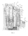
- FIG. 4 A further modification of the coupling arrangement described in FIG is shown in Fig. 4, wherein components, those of the first embodiment correspond, with the same reference numerals, respectively increased around the letter "c", are provided. It will be below the differences have been made, so that, moreover, the description of the first embodiment is referenced.
- Fig. 5 shows another embodiment of the coupling arrangement, wherein Components corresponding to those of the first embodiment, with the same reference numbers, in each case increased by the letter "d" are provided. Only the differences will be discussed below. so that, incidentally, the description of the first embodiment referenced.
- This embodiment differs from the first embodiment essentially in that instead of the tab 102 and the Wire rings 104 for supporting the radially outer portion 88 of the Kraftbeaufschlagungselements 86 of the second coupling portion 14 opposite the wire ring 90 (see Fig. 1) only a clamping ring 122d provided which is in one on the inner circumference of the substantially axially extending Section 30d formed groove 120d is inserted to a Lifting the force application element 86d of the as a fulcrum for the force applying element 86d serving wire ring 90d prevent which is received in a further groove 124d.
- the groove 124d in this embodiment formed by an area 1 26d of the radially after inside annular portion 34 d from the outside (of right) is punched, resulting in a corresponding bulge 128 d at the Inside creates, through which the groove 124d without cutting Processing can be formed. It should be noted, however that are also cutting and other conceivable procedures for Formation of the groove 124d as well as the groove 120d are used.
- the force-applying element 86e for example designed as a diaphragm spring, in its radially outer region 88e in a first axial direction, that is, in one direction on the housing part 28e to or into this, again on the first support element here acting wire ring 90e is supported, namely at the bottom area 34e of the essentially cup-shaped housing part 28e.
- a support ring 200e is provided for support in the other axial direction, ie in the direction of the pressure plate 72e.
- This is on the inside of the peripheral portion 31 e of the housing part 28e on or is there after inserting the wire ring 90e and the Kraftbeaufschlagungselements 86e used and, as indicated in Fig. 6, for example determined by welding.
- the Kraftbeaufschlagungselement 86e biased and in his intended Mounting position is maintained, a backlash-free installation is obtained.
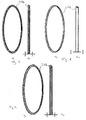
- FIGS. 7-9 show different variants of such a support ring 200e each shown in perspective and in section.
- the shaping of this Support ring 200e can of course be to the shape of the housing part Be adapted 28e and also to the shape or the Dimensioning of the load element 86e.
- the support ring 200e For example, by deep drawing, rolling, welding and calibration, or be made by turning.
- the abutment in the radially inner area also forms this embodiment variant, for example, again the engagement bearing 100e the actuating mechanism 58e, on which the radially inner End portions of the loading member 86e under bias can abut, since an axial deflection in the radially outer region 88e not possible.
- FIG. 10-12 Another variant is shown in Figs. 10-12.
- This support ring 200f has fastening webs at a plurality of circumferential positions 202f, which engage in substantially radially outward Fixing portions 204f end. In the area of these attachment sections 204f, the support ring 200f is fixedly connected to the housing part 28f. It can be seen in Fig. 10 and also in Fig. 12 that this housing part 28f, a radially outwardly engaging flange-type attachment area 33f.
- this attachment area 33f is under Use of the screw 32f the housing part 28f on the abutment plate 26f fixed. At several circumferential positions, this is flange-like However, fastening area 33f is set back axially in order to access sections 35f form, in which Tangentialblattfedern 208f, the other end of the Pressure plate 72f are fixed, with the housing part 28f by riveting or the like. are connected. Together with the tangential leaf springs 208f is then the support ring 200f in the region of its attachment portions 204f fixedly connected to the housing part 28f.
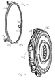
- FIG. 13-17 Another variant is shown in Figs. 13-17.
- the housing part 28g is divided into two parts into a first housing component 210g and a second housing member 212g.
- the second housing component 212g again sets the radially outward-reaching flange Mounting area 33g ready in its area using the Bolt 32g the determination on the abutment plate 26g takes place.
- this housing component 212g which also has an approximately having a cup-like structure with a ring-like open bottom, a Supporting portion 214g ready, at which the radially outer portion 88g of the Kraftbeetzschungselements 86g is supported in the axial direction.
- the second housing member 210g is in its radially outer, circumferential wall-like designed area with the housing member 212g in one Area connected radially outside of the force-applying element 86g, for example, by welding, riveting, press fit or the like.
- This approximately turn cup-shaped housing component 210g provides the bottom portion 34g at which the radial outer portion 88g of the loading member 86g over the Wire ring is supported 90g.
- this embodiment variant corresponds to the structure of the housing component 212g also shown in Fig. 14 and in Fig. 13.
- the housing component 210g carries attachment areas 216g, which in turn Fixing sections 218g end. In the area of these attachment sections 218g, the housing member 210g with the housing member 212g are firmly connected, for example by riveting.
- FIGS. 18-20 Another variant is shown in FIGS. 18-20.
- two housing components 212h and 210h used, between which then the radially outer portion 88h of the loading member 86h axially fixed and held without movement play.
- the housing component 210h is exactly centered, as this also the other support serves.
- the various interlocked and possibly directly interconnected or connected to each other via the abutment plate or fastening bolts Use housing components, these housing components can advantageously made of sheet metal material, which after a punching process be brought by a forming process in the desired shape.
- the main advantages of the foregoing with reference to FIG. 6 - 20 described embodiments are that a substantially backlash-free axial mounting of the diaphragm spring or the Kraftbeetzungselements is obtained, in its radially outer Area is to support with respect to the housing. The danger of at Force deformation of those areas, in which the axial support is made, is possible by the possibility use molded and dimensioned components, largely avoided.
- the Kraftbeaufschlagungs comprise for example, be designed as diaphragm springs, but for example also a power transmission lever assembly with multiple in Circumferentially distributed lever elements comprise, which optionally also be biased towards disengagement or have these associated biasing elements, which the lever elements in the direction of disengage, as long as a biasing the Kraftbeaufschlagungsan ever is possible to one of the beginning of a Engagement action effective engagement force counteracting reaction force provide.
- the force application elements described above are designed so that they only at the beginning of an engagement process provide a reaction force counteracting the effective engagement force, but otherwise provide essentially only low reaction forces, preferably with a neutral or degressive force-displacement behavior, although to raise the starting level of the engagement force, but not or only insignificantly the maximum value of the engagement force, so that a Transformation of the actuating mechanism 58 to achieve higher Engagement forces (maximum achievable engagement forces) is not necessary.
Landscapes
- Engineering & Computer Science (AREA)
- General Engineering & Computer Science (AREA)
- Mechanical Engineering (AREA)
- Mechanical Operated Clutches (AREA)
- Braking Arrangements (AREA)
Abstract
Description
- Fig. 1
- eine Teillängsschnittansicht einer Doppelkupplung;
- Fig. 2
- eine Ansicht entsprechend Fig. 1 einer weiteren Ausführungsform einer Doppelkupplung in Übereinstimmung mit der Erfindung;
- Fig. 3
- eine Ansicht entsprechend Fig. 1 einer weiteren Ausführungsform einer Doppelkupplung in Übereinstimmung mit der Erfindung;
- Fig. 4
- eine Ansicht entsprechend Fig. 1 einer weiteren Ausführungsform einer Doppelkupplung in Übereinstimmung mit der Erfindung;
- Fig. 5
- eine vergrößerte Teillängsschnittansicht gemäß einer weiteren Ausführungsform einer Kupplung in Übereinstimmung mit der Erfindung;
- Fig. 6
- ein der Fig. 1 entsprechende Darstellung einer Doppelkupplung mit einer alternativen Variante der beidseitigen axialen Abstützung einer Kraftbeaufschlagungsanordnung;
- Fig. 7 - 9
- verschiedene Varianten eines ringartigen Abstützelements;
- Fig. 10
- eine der Fig. 6 entsprechende Ansicht mit einer weiteren Alternative zur beidseitigen axialen Abstützung einer Kraftbeaufschlagungsanordnung;
- Fig. 11
- eine perspektivische Ansicht eines bei der Variante der Fig. 10 eingesetzten Axialabstützelements;
- Fig. 12
- eine perspektivische Ansicht des bei der Variante der Fig. 10 eingesetzten Gehäuses;
- Fig. 13
- eine weitere der Fig. 6 entsprechende Ausgestaltungsvariante mit alternativer beidseitiger Axialabstützung;
- Fig. 14 und 15
- perspektivisch dargestellt zwei Gehäuseteile der Ausgestaltungsform der Fig. 13;
- Fig. 16 und 17
- eine perspektivische Darstellung zweier Gehäuseteile gemäß einer alternativen Ausgestaltungsform;
- Fig. 18
- eine weitere der Fig. 6 entsprechende Ansicht mit einer weiteren Variante der beidseitigen axialen Abstützung einer Kraftbeaufschlagungsanordnung;
- Fig. 19
- eine perspektivische Ansicht eines bei der Ausgestaltungsform der Fig. 18 eingesetzten Gehäuseteils;
- Fig. 20
- eine perspektivische Ansicht eines weiteren bei der Ausgestaltungsform der Fig. 18 eingesetzten Gehäuseteils.
Claims (22)
- Reibungskupplung, umfassend eine Gehäuseanordnung (16; 16a; 16b; 16c; 16d; 16e; 16f; 16g; 16h), eine Anpressplatte (38, 72; 38a, 72a; 38b, 72b; 38c, 72c; 72d; 72e; 72f; 72g; 72h), welche mit der Gehäuseanordnung (16; 16a; 16b; 16c; 16d; 16e; 16f; 16g; 16h) zur gemeinsamen Drehung um eine Drehachse (A) und in Richtung der Drehachse (A) bezüglich dieser verlagerbar gekoppelt ist, ein Einrückersystem (58; 58a; 58b; 58c; 58e; 58f; 58g; 58h) zur Erzeugung einer Einrückkraft, eine Kraftbeaufschlagungsanordnung (54, 86; 54a, 86a; 54b, 86b; 54c, 86c; 86d; 86e; 86f; 86g; 86h) zur Übertragung der Einrückkraft auf die Anpressplatte (38, 72; 38a, 72a; 38b, 72b; 38c, 72c; 72d; 72e; 72f; 72g; 72h), wobei die Kraftbeaufschlagungsanordnung (54, 86; 54a, 86a; 54b, 86b; 54c, 86c; 86d; 86e; 86f; 86g; 86h) vorgespannt ist, um eine der am Beginn eines Einrückvorgangs wirkenden Einrückkraft entgegenwirkende Reaktionskraft bereitzustellen.
- Reibungskupplung nach Anspruch 1,
dadurch gekennzeichnet, dass eine Kraftbeaufschlagungsanordnung (86; 86a; 86b; 86c; 86d; 86e; 86f; 86g; 86h) in ihrem radial äußeren Randbereich (88; 88a; 88b; 88c; 88d; 88e; 88f; 88g; 88h) bezüglich der Gehäuseanordnung (16; 16a; 16b; 16c; 16d; 16e; 16g; 16g; 16h) und in einem radial weiter innen gelegenen Bereich (92; 92a; 92b; 92c; 92d; 92e; 92f; 92g; 92h) bezüglich der Anpressplatte (72; 72a; 72b; 72c; 72d; 72e; 72f; 72g; 72h) abgestützt ist. - Reibungskupplung nach Anspruch 1 oder 2,
dadurch gekennzeichnet, dass eine Kraftbeaufschlagungsanordnung (54; 54a; 54b; 54c) in ihrem radial äußeren Randbereich (64; 64a; 64b; 64c) bezüglich der Anpressplatte (38; 38a; 38b; 38c) und in einem radial weiter innen gelegenen Bereich (66; 66a; 66b; 66c) bezüglich der Gehäuseanordnung (16; 16a; 16b; 16c; 16d) abgestützt ist. - Reibungskupplung nach Anspruch 2 oder 3,
dadurch gekennzeichnet, dass die Kraftbeaufschlagungsanordnung (54, 86; 54a, 86a; 54b, 86b; 54c, 86c; 86d; 86e; 86f; 86g; 86h) bezüglich der Gehäuseanordnung (16; 16a; 16b; 16c; 16d; 16e; 16f; 16g; 16h) in beiden axialen Richtungen abgestützt ist. - Reibungskupplung nach Anspruch 4,
dadurch gekennzeichnet, dass die Abstützung in einer ersten axialen Richtung über ein an einem Bodenbereich (34; 34a; 34b; 34c; 34d; 34e; 34f; 34g; 34h) des Gehäuses (16; 16a; 16b; 16c; 16d; 16e; 16f; 16g; 16h) sich abstützendes erstes Abstützelement (90; 90a; 90b; 90c; 90d; 90f; 90g; 90h) erfolgt. - Reibungskupplung nach Anspruch 4 oder 5,
dadurch gekennzeichnet, dass die Abstützung in einer zweiten axialen Richtung über an dem Gehäuse (16; 16a; 16b; 16c) integral vorgesehene, durch Umformung des Gehäuses (16; 16a; 16b; 16c) gebildete Abstützbereiche (102; 102a; 102b; 102c) erfolgt. - Reibungskupplung nach Anspruch 4 oder 5,
dadurch gekennzeichnet, dass die Abstützung in einer zweiten axialen Richtung über ein mit dem Gehäuse (16e; 16f) axial fest verbundenes zweites Abstützelement (200e; 200f) erfolgt. - Reibungskupplung nach Anspruch 7,
dadurch gekennzeichnet, dass das zweite Abstützelement (200e; 200f) mit dem Gehäuse (16e; 16f) durch Formschluss, Materialschluss, insbesondere Verschweißung, oder unter Einsatz von Befestigungselementen fest verbunden ist. - Reibungskupplung nach Anspruch 4,
dadurch gekennzeichnet, dass das Gehäuse (16g; 16h) ein erstes Gehäusebauteil (210g; 210h) umfasst, an dem die Abstützung in einer ersten axialen Richtung erfolgt, und ein zweites Gehäusebauteil (212g; 212h) umfasst, an dem die Abstützung in einer zweiten axialen Richtung erfolgt. - Reibungskupplung nach Anspruch 9,
dadurch gekennzeichnet, dass das erste Gehäusebauteil (210g) an dem zweiten Gehäusebauteil (212g) getragen ist. - Reibungskupplung nach Anspruch 9,
dadurch gekennzeichnet, dass das erste Gehäusebauteil (210h) und das zweite Gehäusebauteil (212h) an einem gemeinsamen Träger (26h) getragen sind. - Reibungskupplung nach einem der vorhergehenden Ansprüche,
dadurch gekennzeichnet, dass die Kraftbeaufschlagungsanordnung (54, 86; 54a, 86a; 54b, 86b; 54c, 86c) in einem maximal entspannten Zustand durch eine Abstützung an einer Vorspannanschlaganordnung (100, 110; 112a, 116a; 98b, 100b; 98c, 100c) in einem Vorspannzustand gehalten ist. - Reibungskupplung nach Anspruch 12,
dadurch gekennzeichnet, dass die Vorspannanschlaganordnung (100; 98b, 100b; 98c, 100c) vom Einrückersystem (58; 58b; 58c) gebildet ist. - Reibungskupplung nach Anspruch 12 oder 13,
dadurch gekennzeichnet, dass die Vorspannanschlaganordnung (110; 112a, 116a) an der Gehäuseanordnung (16; 16a) vorgesehen ist. - Reibungskupplung nach Anspruch 3 und einem der Ansprüche 4 bis 14, sofern auf Anspruch 3 zurückbezogen,
dadurch gekennzeichnet, dass die Vorspannanschlaganordnung (110; 116a) einen radial äußeren Randbereich (64; 64a) der Kraftbeaufschlagungsanordnung (54; 54a) abstützt. - Reibungskupplung nach Anspruch 2 und einem der Ansprüche 4 bis 14, sofern auf Anspruch 2 zurückbezogen,
dadurch gekennzeichnet, dass die Vorspannanschlaganordnung (112a) in einem gegenüber dem äußeren Randbereich (88a) der Kraftbeaufschlagungsanordnung (86a) radial weiter innen gelegenen Bereich (92a) zur Abstützung vorgesehen ist. - Reibungskupplung nach einem der Ansprüche 15 oder 16,
dadurch gekennzeichnet, dass die Abstützung innerhalb eines Bereichs (64; 64a, 92a) erfolgt, in welchem die Anpressplatte (38; 38a, 72a) an der Kraftbeaufschlagungsanordnung (54; 54a, 86a) abgestützt ist. - Reibungskupplung nach einem der vorhergehenden Ansprüche,
dadurch gekennzeichnet, dass die Kraftbeaufschlagungsanordnung (54, 86; 54a, 86a; 54b, 86b; 54c, 86c; 86d) wenigstens ein Membranfederelement (54, 86; 54a, 86a; 54b, 86b; 54c, 86c; 86d) umfasst. - Reibungskupplung nach einem der vorhergehenden Ansprüche, dadurch gekennzeichnet, dass die Kraftbeaufschlagungsanordnung mehrere Hebelelemente umfasst, welche in Richtung Ausrücken vorgespannt sind.
- Reibungskupplung nach Anspruch 12, dadurch gekennzeichnet, dass den Hebelelementen Vorspannelemente zugeordnet sind, welche die Hebelelemente in Richtung Ausrücken vorspannen.
- Reibungskupplung, umfassend eine Gehäuseanordnung (16; 16a; 16b; 16c; 16d; 16e; 16f; 16g; 16h), eine Anpressplatte (38, 72; 72a; 72b; 72c; 72d; 72e; 72f; 72g; 72h), welche mit der Gehäuseanordnung (16; 16a; 16b; 16c; 16d; 16e; 16f; 16g; 16h) zur gemeinsamen Drehung um eine Drehachse (A) und in Richtung der Drehachse (A) bezüglich dieser verlagerbar gekoppelt ist, ein Einrückersystem (58; 58a; 58b; 58c; 58e; 58f; 58g; 58h) zur Erzeugung einer Einrückkraft, eine Kraftbeaufschlagungsanordnung (86; 86a; 86b; 86c; 86d; 86e; 86f; 86g; 86h) zur Übertragung der Einrückkraft auf die Anpressplatte (72; 72a; 72b; 72c; 72d; 72e; 72f; 72g; 72h), wobei die Kraftbeaufschlagungsanordnung (86; 86a; 86b; 86c; 86d; 86e; 86f; 86g; 86h) in ihrem radial äußeren Randbereich (88; 88a; 88b; 88c; 88d; 88e; 88f; 88g; 88h) bezüglich der Gehäuseanordnung (16; 16a; 16b; 16c; 16d; 16e; 16g; 16g; 16h) und in einem radial weiter innen gelegenen Bereich (92; 92a; 92b; 92c; 92d; 92e; 92f; 92g; 92h) bezüglich der Anpressplatte (72; 72a; 72b; 72c; 72d; 72e; 72f; 72g; 72h) abgestützt ist, und wobei die Kraftbeaufschlagungsanordnung (86; 86a; 86b; 86c; 86d; 86e; 86f; 86g; 86h) bezüglich der Gehäuseanordnung (16; 16a; 16b; 16c; 16d; 16e; 16f; 16g; 16h) in beiden axialen Richtungen abgestützt ist.
- Reibungskupplung, insbesondere Doppelkupplung nach einem der Ansprüche 1 bis 21, dadurch gekennzeichnet, dass zwei Kupplungsbereiche (12, 14; 12a, 14a; 12b, 14b; 12c, 14c; 12e, 14e; 12f, 14f; 12g, 14g; 12h, 14h) vorgesehen sind, wobei in einem der Kupplungsbereiche (14; 14a; 14b; 14c; 14e; 14f; 14g; 14h) die Kraftbeaufschlagungsanordnung (86; 86a; 86b; 86c) in einem radial äußeren Randbereich (88; 88a; 88b; 88c; 88e; 88f; 88g; 88h) bezüglich der Gehäuseanordnung (16; 16a; 16b; 16c; 16e; 16f; 16g; 16h) und in einem radial weiter innen gelegenen Bereich (92; 92a; 92b; 92c; 92e; 92f; 92g; 92h) bezüglich der Anpressplatte (72; 72a; 72b; 72c; 72e; 72f; 72g; 72h) abgestützt ist und wobei in dem anderen Kupplungsbereich (12; 12a; 12b; 12c; 12e; 12f; 12g; 12h) die Kraftbeaufschlagungsanordnung (54; 54a; 54b; 54c; 54e; 54f; 54g; 54h) in einem radial äußeren Randbereich (64; 64a; 64b; 64c; 64e; 64f; 64g; 64h) bezüglich der Anpressplatte (38; 38a; 38b; 38c; 38e; 38f; 38g; 38h) und in einem radial weiter innen gelegenen Bereich (66; 66a; 66b; 66c; 66e; 66f; 66g; 66h) bezüglich der Gehäuseanordnung (16; 16a; 16b; 16c; 16e; 16f; 16g; 16h) abgestützt ist.
Applications Claiming Priority (2)
| Application Number | Priority Date | Filing Date | Title |
|---|---|---|---|
| DE10304058 | 2003-02-01 | ||
| DE10304058 | 2003-02-01 |
Publications (3)
| Publication Number | Publication Date |
|---|---|
| EP1443233A1 true EP1443233A1 (de) | 2004-08-04 |
| EP1443233B1 EP1443233B1 (de) | 2010-09-29 |
| EP1443233B2 EP1443233B2 (de) | 2020-07-29 |
Family
ID=32603095
Family Applications (1)
| Application Number | Title | Priority Date | Filing Date |
|---|---|---|---|
| EP04002150.3A Expired - Lifetime EP1443233B2 (de) | 2003-02-01 | 2004-01-30 | Reibungskupplung |
Country Status (3)
| Country | Link |
|---|---|
| EP (1) | EP1443233B2 (de) |
| AT (1) | ATE483115T1 (de) |
| DE (3) | DE102004003285A1 (de) |
Cited By (1)
| Publication number | Priority date | Publication date | Assignee | Title |
|---|---|---|---|---|
| WO2006012972A1 (de) * | 2004-07-30 | 2006-02-09 | Zf Friedrichshafen Ag | Reibungskupplung vom no-typ |
Families Citing this family (3)
| Publication number | Priority date | Publication date | Assignee | Title |
|---|---|---|---|---|
| DE102007060798B4 (de) | 2007-12-18 | 2014-03-20 | BSH Bosch und Siemens Hausgeräte GmbH | Vorrichtung zum Emulgieren einer Mischung aus Luft, Dampf und Milch |
| DE102008018007B4 (de) | 2008-04-09 | 2021-04-29 | BSH Hausgeräte GmbH | Vorrichtung zum Emulgieren einer Mischung aus Luft, Dampf und Milch |
| DE102021105911A1 (de) | 2021-03-11 | 2022-09-15 | Schaeffler Technologies AG & Co. KG | Druckring mit werkzeugfallend ausgeformter axialer Anschlagskontur für einen Sicherungsring; Druckringanordnung sowie Reibkupplung |
Citations (7)
| Publication number | Priority date | Publication date | Assignee | Title |
|---|---|---|---|---|
| US4579210A (en) * | 1982-10-30 | 1986-04-01 | Fichtel & Sachs Ag | Pressure plate unit for a motor vehicle friction clutch |
| GB2186039A (en) * | 1986-02-04 | 1987-08-05 | Automotive Products Plc | Friction clutch cover assembly |
| EP0249469A2 (de) * | 1986-06-13 | 1987-12-16 | Automotive Products Public Limited Company | Reibungskupplungsgehäuse |
| US5265709A (en) * | 1990-09-28 | 1993-11-30 | Kabushiki Kaisha Daikin Seisakusho | Pull-type clutch cover assembly |
| US5586634A (en) * | 1992-12-17 | 1996-12-24 | Valeo | Clutch mechanism, especially for a motor vehicle |
| US5927418A (en) | 1996-06-13 | 1999-07-27 | Exedy Corporation | Power transmission device in a fluid pressure accumulating hybrid vehicle |
| FR2834024A1 (fr) * | 2001-12-20 | 2003-06-27 | Valeo | Mecanisme d'embrayage, notamment pour vehicule automobile |
Family Cites Families (5)
| Publication number | Priority date | Publication date | Assignee | Title |
|---|---|---|---|---|
| DE3446460A1 (de) † | 1984-12-20 | 1986-07-03 | Dr.Ing.H.C. F. Porsche Ag, 7000 Stuttgart | Doppelkupplung fuer ein kraftfahrzeuggetriebe |
| FR2745051B1 (fr) † | 1996-02-20 | 1998-04-10 | Valeo | Montage de butee de debrayage, notamment pour vehicule automobile |
| DE19622773C1 (de) † | 1996-06-07 | 1997-05-07 | Fichtel & Sachs Ag | Nehmerzylinder zur Betätigung einer Reibkupplung |
| FR2756602B1 (fr) † | 1996-11-29 | 1999-01-15 | Skf France | Dispositif debrayeur |
| DE10134118B4 (de) † | 2001-07-13 | 2013-02-21 | Volkswagen Ag | Doppelkupplung |
-
2004
- 2004-01-22 DE DE102004003285A patent/DE102004003285A1/de not_active Withdrawn
- 2004-01-30 EP EP04002150.3A patent/EP1443233B2/de not_active Expired - Lifetime
- 2004-01-30 DE DE502004011692T patent/DE502004011692D1/de not_active Expired - Lifetime
- 2004-01-30 AT AT04002150T patent/ATE483115T1/de not_active IP Right Cessation
- 2004-01-30 DE DE102004004861A patent/DE102004004861A1/de not_active Ceased
Patent Citations (7)
| Publication number | Priority date | Publication date | Assignee | Title |
|---|---|---|---|---|
| US4579210A (en) * | 1982-10-30 | 1986-04-01 | Fichtel & Sachs Ag | Pressure plate unit for a motor vehicle friction clutch |
| GB2186039A (en) * | 1986-02-04 | 1987-08-05 | Automotive Products Plc | Friction clutch cover assembly |
| EP0249469A2 (de) * | 1986-06-13 | 1987-12-16 | Automotive Products Public Limited Company | Reibungskupplungsgehäuse |
| US5265709A (en) * | 1990-09-28 | 1993-11-30 | Kabushiki Kaisha Daikin Seisakusho | Pull-type clutch cover assembly |
| US5586634A (en) * | 1992-12-17 | 1996-12-24 | Valeo | Clutch mechanism, especially for a motor vehicle |
| US5927418A (en) | 1996-06-13 | 1999-07-27 | Exedy Corporation | Power transmission device in a fluid pressure accumulating hybrid vehicle |
| FR2834024A1 (fr) * | 2001-12-20 | 2003-06-27 | Valeo | Mecanisme d'embrayage, notamment pour vehicule automobile |
Cited By (1)
| Publication number | Priority date | Publication date | Assignee | Title |
|---|---|---|---|---|
| WO2006012972A1 (de) * | 2004-07-30 | 2006-02-09 | Zf Friedrichshafen Ag | Reibungskupplung vom no-typ |
Also Published As
| Publication number | Publication date |
|---|---|
| EP1443233B2 (de) | 2020-07-29 |
| DE102004003285A1 (de) | 2004-08-12 |
| DE102004004861A1 (de) | 2004-08-12 |
| ATE483115T1 (de) | 2010-10-15 |
| EP1443233B1 (de) | 2010-09-29 |
| DE502004011692D1 (de) | 2010-11-11 |
Similar Documents
| Publication | Publication Date | Title |
|---|---|---|
| EP2906846B1 (de) | Reibungskupplungseinrichtung | |
| EP1862689B1 (de) | Drehmomentübertragungsanordnung für den Antriebsstrang eines Fahrzeugs | |
| EP2861883A1 (de) | Reibungskupplung | |
| WO2015120845A1 (de) | Normal-eingerückte kupplungsvorrichtung | |
| DE102010006055A1 (de) | Kupplungsaggregat | |
| DE112014001037B4 (de) | Reibungskupplung | |
| DE69503721T2 (de) | Drehschwingungsdämpfer, insbesondere für Kraftfahrzeuge | |
| EP1443233B1 (de) | Reibungskupplung | |
| EP3332140B1 (de) | Reibungskupplungseinrichtung | |
| DE102011086009A1 (de) | Selbstnachstellende Kupplung | |
| DE102011003030A1 (de) | Kupplungsscheibe für eine Reibungskupplung eines Kraftfahrzeugs | |
| DE102014216346B4 (de) | Tellerfeder für eine Reibungskupplung und Verfahren zu deren Herstellung | |
| DE102013226470A1 (de) | Nachstelleinrichtung für eine Reibungskupplung sowie Verfahren zur Herstellung einer Nachstelleinrichtung | |
| DE102014208097A1 (de) | Reibungskupplungseinrichtung | |
| DE102013217050A1 (de) | Reibungskupplungseinrichtung | |
| EP1907718B1 (de) | Hebelanordnung für eine reibungskupplung sowie reibungskupplung mit einer solchen hebelanordnung | |
| DE102008042659A1 (de) | Reibungskupplung | |
| DE102014210994A1 (de) | Kupplungsdeckel mit separatem Anschlagsbauteil | |
| DE102005049669A1 (de) | Kupplungsscheibenanordnung für eine Mehrscheibenkupplung | |
| EP1774193B1 (de) | Reibungskupplung vom normal-offen-typ | |
| DE102016204839B3 (de) | Mehrteilige Teller-/ oder Hebelfeder mit zwischengeschaltetem Dämpfungselement | |
| DE102012207022A1 (de) | Kupplungsvorrichtung | |
| DE102016219673A1 (de) | Reibelement, Reibungskupplung und Antriebsstrang | |
| DE102012211832A1 (de) | Reibungskupplung | |
| DE102012218573A1 (de) | Anpressplatte für eine Kupplungsvorrichtung und Kupplungsvorrichtung |
Legal Events
| Date | Code | Title | Description |
|---|---|---|---|
| PUAI | Public reference made under article 153(3) epc to a published international application that has entered the european phase |
Free format text: ORIGINAL CODE: 0009012 |
|
| AK | Designated contracting states |
Kind code of ref document: A1 Designated state(s): AT BE BG CH CY CZ DE DK EE ES FI FR GB GR HU IE IT LI LU MC NL PT RO SE SI SK TR |
|
| AX | Request for extension of the european patent |
Extension state: AL LT LV MK |
|
| 17P | Request for examination filed |
Effective date: 20040714 |
|
| 17Q | First examination report despatched |
Effective date: 20040906 |
|
| AKX | Designation fees paid |
Designated state(s): AT BE BG CH CY CZ DE DK EE ES FI FR GB GR HU IE IT LI LU MC NL PT RO SE SI SK TR |
|
| GRAP | Despatch of communication of intention to grant a patent |
Free format text: ORIGINAL CODE: EPIDOSNIGR1 |
|
| GRAS | Grant fee paid |
Free format text: ORIGINAL CODE: EPIDOSNIGR3 |
|
| GRAA | (expected) grant |
Free format text: ORIGINAL CODE: 0009210 |
|
| AK | Designated contracting states |
Kind code of ref document: B1 Designated state(s): AT BE BG CH CY CZ DE DK EE ES FI FR GB GR HU IE IT LI LU MC NL PT RO SE SI SK TR |
|
| REG | Reference to a national code |
Ref country code: GB Ref legal event code: FG4D Free format text: NOT ENGLISH |
|
| REG | Reference to a national code |
Ref country code: CH Ref legal event code: EP |
|
| REG | Reference to a national code |
Ref country code: IE Ref legal event code: FG4D Free format text: LANGUAGE OF EP DOCUMENT: GERMAN |
|
| REF | Corresponds to: |
Ref document number: 502004011692 Country of ref document: DE Date of ref document: 20101111 Kind code of ref document: P |
|
| PG25 | Lapsed in a contracting state [announced via postgrant information from national office to epo] |
Ref country code: FI Free format text: LAPSE BECAUSE OF FAILURE TO SUBMIT A TRANSLATION OF THE DESCRIPTION OR TO PAY THE FEE WITHIN THE PRESCRIBED TIME-LIMIT Effective date: 20100929 |
|
| REG | Reference to a national code |
Ref country code: NL Ref legal event code: VDEP Effective date: 20100929 |
|
| PG25 | Lapsed in a contracting state [announced via postgrant information from national office to epo] |
Ref country code: SI Free format text: LAPSE BECAUSE OF FAILURE TO SUBMIT A TRANSLATION OF THE DESCRIPTION OR TO PAY THE FEE WITHIN THE PRESCRIBED TIME-LIMIT Effective date: 20100929 |
|
| PG25 | Lapsed in a contracting state [announced via postgrant information from national office to epo] |
Ref country code: SE Free format text: LAPSE BECAUSE OF FAILURE TO SUBMIT A TRANSLATION OF THE DESCRIPTION OR TO PAY THE FEE WITHIN THE PRESCRIBED TIME-LIMIT Effective date: 20100929 Ref country code: GR Free format text: LAPSE BECAUSE OF FAILURE TO SUBMIT A TRANSLATION OF THE DESCRIPTION OR TO PAY THE FEE WITHIN THE PRESCRIBED TIME-LIMIT Effective date: 20101230 |
|
| REG | Reference to a national code |
Ref country code: IE Ref legal event code: FD4D |
|
| PG25 | Lapsed in a contracting state [announced via postgrant information from national office to epo] |
Ref country code: SK Free format text: LAPSE BECAUSE OF FAILURE TO SUBMIT A TRANSLATION OF THE DESCRIPTION OR TO PAY THE FEE WITHIN THE PRESCRIBED TIME-LIMIT Effective date: 20100929 Ref country code: RO Free format text: LAPSE BECAUSE OF FAILURE TO SUBMIT A TRANSLATION OF THE DESCRIPTION OR TO PAY THE FEE WITHIN THE PRESCRIBED TIME-LIMIT Effective date: 20100929 Ref country code: PT Free format text: LAPSE BECAUSE OF FAILURE TO SUBMIT A TRANSLATION OF THE DESCRIPTION OR TO PAY THE FEE WITHIN THE PRESCRIBED TIME-LIMIT Effective date: 20110131 Ref country code: CZ Free format text: LAPSE BECAUSE OF FAILURE TO SUBMIT A TRANSLATION OF THE DESCRIPTION OR TO PAY THE FEE WITHIN THE PRESCRIBED TIME-LIMIT Effective date: 20100929 Ref country code: EE Free format text: LAPSE BECAUSE OF FAILURE TO SUBMIT A TRANSLATION OF THE DESCRIPTION OR TO PAY THE FEE WITHIN THE PRESCRIBED TIME-LIMIT Effective date: 20100929 Ref country code: NL Free format text: LAPSE BECAUSE OF FAILURE TO SUBMIT A TRANSLATION OF THE DESCRIPTION OR TO PAY THE FEE WITHIN THE PRESCRIBED TIME-LIMIT Effective date: 20100929 Ref country code: IT Free format text: LAPSE BECAUSE OF FAILURE TO SUBMIT A TRANSLATION OF THE DESCRIPTION OR TO PAY THE FEE WITHIN THE PRESCRIBED TIME-LIMIT Effective date: 20100929 |
|
| PLBI | Opposition filed |
Free format text: ORIGINAL CODE: 0009260 |
|
| PG25 | Lapsed in a contracting state [announced via postgrant information from national office to epo] |
Ref country code: ES Free format text: LAPSE BECAUSE OF FAILURE TO SUBMIT A TRANSLATION OF THE DESCRIPTION OR TO PAY THE FEE WITHIN THE PRESCRIBED TIME-LIMIT Effective date: 20110109 Ref country code: IE Free format text: LAPSE BECAUSE OF FAILURE TO SUBMIT A TRANSLATION OF THE DESCRIPTION OR TO PAY THE FEE WITHIN THE PRESCRIBED TIME-LIMIT Effective date: 20100929 |
|
| BERE | Be: lapsed |
Owner name: ZF SACHS A.G. Effective date: 20110131 |
|
| PLAX | Notice of opposition and request to file observation + time limit sent |
Free format text: ORIGINAL CODE: EPIDOSNOBS2 |
|
| 26 | Opposition filed |
Opponent name: VALEO EMBRAYAGES Effective date: 20110629 |
|
| PG25 | Lapsed in a contracting state [announced via postgrant information from national office to epo] |
Ref country code: DK Free format text: LAPSE BECAUSE OF FAILURE TO SUBMIT A TRANSLATION OF THE DESCRIPTION OR TO PAY THE FEE WITHIN THE PRESCRIBED TIME-LIMIT Effective date: 20100929 Ref country code: MC Free format text: LAPSE BECAUSE OF NON-PAYMENT OF DUE FEES Effective date: 20110131 |
|
| REG | Reference to a national code |
Ref country code: CH Ref legal event code: PL |
|
| PLBB | Reply of patent proprietor to notice(s) of opposition received |
Free format text: ORIGINAL CODE: EPIDOSNOBS3 |
|
| GBPC | Gb: european patent ceased through non-payment of renewal fee |
Effective date: 20110130 |
|
| REG | Reference to a national code |
Ref country code: DE Ref legal event code: R026 Ref document number: 502004011692 Country of ref document: DE Effective date: 20110629 |
|
| PG25 | Lapsed in a contracting state [announced via postgrant information from national office to epo] |
Ref country code: LI Free format text: LAPSE BECAUSE OF NON-PAYMENT OF DUE FEES Effective date: 20110131 Ref country code: CH Free format text: LAPSE BECAUSE OF NON-PAYMENT OF DUE FEES Effective date: 20110131 |
|
| RAP2 | Party data changed (patent owner data changed or rights of a patent transferred) |
Owner name: ZF FRIEDRICHSHAFEN AG |
|
| PG25 | Lapsed in a contracting state [announced via postgrant information from national office to epo] |
Ref country code: BE Free format text: LAPSE BECAUSE OF NON-PAYMENT OF DUE FEES Effective date: 20110131 Ref country code: GB Free format text: LAPSE BECAUSE OF NON-PAYMENT OF DUE FEES Effective date: 20110130 |
|
| REG | Reference to a national code |
Ref country code: AT Ref legal event code: MM01 Ref document number: 483115 Country of ref document: AT Kind code of ref document: T Effective date: 20110130 |
|
| REG | Reference to a national code |
Ref country code: DE Ref legal event code: R082 Ref document number: 502004011692 Country of ref document: DE Representative=s name: PATENTANWAELTE WEICKMANN & WEICKMANN, DE Effective date: 20120301 Ref country code: DE Ref legal event code: R082 Ref document number: 502004011692 Country of ref document: DE Effective date: 20120301 Ref country code: DE Ref legal event code: R081 Ref document number: 502004011692 Country of ref document: DE Owner name: ZF FRIEDRICHSHAFEN AG, DE Free format text: FORMER OWNER: ZF SACHS AG, 97424 SCHWEINFURT, DE Effective date: 20120301 |
|
| REG | Reference to a national code |
Ref country code: FR Ref legal event code: TP Owner name: ZF FRIEDRICHSHAFEN AG, DE Effective date: 20120413 |
|
| RDAF | Communication despatched that patent is revoked |
Free format text: ORIGINAL CODE: EPIDOSNREV1 |
|
| APAH | Appeal reference modified |
Free format text: ORIGINAL CODE: EPIDOSCREFNO |
|
| APBM | Appeal reference recorded |
Free format text: ORIGINAL CODE: EPIDOSNREFNO |
|
| APBP | Date of receipt of notice of appeal recorded |
Free format text: ORIGINAL CODE: EPIDOSNNOA2O |
|
| APBQ | Date of receipt of statement of grounds of appeal recorded |
Free format text: ORIGINAL CODE: EPIDOSNNOA3O |
|
| PG25 | Lapsed in a contracting state [announced via postgrant information from national office to epo] |
Ref country code: AT Free format text: LAPSE BECAUSE OF NON-PAYMENT OF DUE FEES Effective date: 20110130 |
|
| PLAB | Opposition data, opponent's data or that of the opponent's representative modified |
Free format text: ORIGINAL CODE: 0009299OPPO |
|
| R26 | Opposition filed (corrected) |
Opponent name: VALEO EMBRAYAGES Effective date: 20110629 |
|
| PG25 | Lapsed in a contracting state [announced via postgrant information from national office to epo] |
Ref country code: CY Free format text: LAPSE BECAUSE OF FAILURE TO SUBMIT A TRANSLATION OF THE DESCRIPTION OR TO PAY THE FEE WITHIN THE PRESCRIBED TIME-LIMIT Effective date: 20100929 Ref country code: LU Free format text: LAPSE BECAUSE OF NON-PAYMENT OF DUE FEES Effective date: 20110130 |
|
| PG25 | Lapsed in a contracting state [announced via postgrant information from national office to epo] |
Ref country code: TR Free format text: LAPSE BECAUSE OF FAILURE TO SUBMIT A TRANSLATION OF THE DESCRIPTION OR TO PAY THE FEE WITHIN THE PRESCRIBED TIME-LIMIT Effective date: 20100929 Ref country code: BG Free format text: LAPSE BECAUSE OF FAILURE TO SUBMIT A TRANSLATION OF THE DESCRIPTION OR TO PAY THE FEE WITHIN THE PRESCRIBED TIME-LIMIT Effective date: 20101229 |
|
| PG25 | Lapsed in a contracting state [announced via postgrant information from national office to epo] |
Ref country code: HU Free format text: LAPSE BECAUSE OF FAILURE TO SUBMIT A TRANSLATION OF THE DESCRIPTION OR TO PAY THE FEE WITHIN THE PRESCRIBED TIME-LIMIT Effective date: 20100929 |
|
| REG | Reference to a national code |
Ref country code: DE Ref legal event code: R082 Ref document number: 502004011692 Country of ref document: DE |
|
| APBU | Appeal procedure closed |
Free format text: ORIGINAL CODE: EPIDOSNNOA9O |
|
| REG | Reference to a national code |
Ref country code: FR Ref legal event code: PLFP Year of fee payment: 13 |
|
| APBM | Appeal reference recorded |
Free format text: ORIGINAL CODE: EPIDOSNREFNO |
|
| APBP | Date of receipt of notice of appeal recorded |
Free format text: ORIGINAL CODE: EPIDOSNNOA2O |
|
| APAH | Appeal reference modified |
Free format text: ORIGINAL CODE: EPIDOSCREFNO |
|
| APAJ | Date of receipt of notice of appeal modified |
Free format text: ORIGINAL CODE: EPIDOSCNOA2O |
|
| APBM | Appeal reference recorded |
Free format text: ORIGINAL CODE: EPIDOSNREFNO |
|
| APBP | Date of receipt of notice of appeal recorded |
Free format text: ORIGINAL CODE: EPIDOSNNOA2O |
|
| PLAB | Opposition data, opponent's data or that of the opponent's representative modified |
Free format text: ORIGINAL CODE: 0009299OPPO |
|
| R26 | Opposition filed (corrected) |
Opponent name: VALEO EMBRAYAGES Effective date: 20110629 |
|
| APBQ | Date of receipt of statement of grounds of appeal recorded |
Free format text: ORIGINAL CODE: EPIDOSNNOA3O |
|
| REG | Reference to a national code |
Ref country code: FR Ref legal event code: PLFP Year of fee payment: 14 |
|
| REG | Reference to a national code |
Ref country code: FR Ref legal event code: PLFP Year of fee payment: 15 |
|
| PLAB | Opposition data, opponent's data or that of the opponent's representative modified |
Free format text: ORIGINAL CODE: 0009299OPPO |
|
| R26 | Opposition filed (corrected) |
Opponent name: VALEO EMBRAYAGES Effective date: 20110629 |
|
| APBU | Appeal procedure closed |
Free format text: ORIGINAL CODE: EPIDOSNNOA9O |
|
| PGFP | Annual fee paid to national office [announced via postgrant information from national office to epo] |
Ref country code: FR Payment date: 20191216 Year of fee payment: 17 |
|
| PGFP | Annual fee paid to national office [announced via postgrant information from national office to epo] |
Ref country code: DE Payment date: 20200114 Year of fee payment: 17 |
|
| PUAH | Patent maintained in amended form |
Free format text: ORIGINAL CODE: 0009272 |
|
| STAA | Information on the status of an ep patent application or granted ep patent |
Free format text: STATUS: PATENT MAINTAINED AS AMENDED |
|
| 27A | Patent maintained in amended form |
Effective date: 20200729 |
|
| AK | Designated contracting states |
Kind code of ref document: B2 Designated state(s): AT BE BG CH CY CZ DE DK EE ES FI FR GB GR HU IE IT LI LU MC NL PT RO SE SI SK TR |
|
| REG | Reference to a national code |
Ref country code: DE Ref legal event code: R102 Ref document number: 502004011692 Country of ref document: DE |
|
| REG | Reference to a national code |
Ref country code: DE Ref legal event code: R119 Ref document number: 502004011692 Country of ref document: DE |
|
| PG25 | Lapsed in a contracting state [announced via postgrant information from national office to epo] |
Ref country code: FR Free format text: LAPSE BECAUSE OF NON-PAYMENT OF DUE FEES Effective date: 20210131 |
|
| PG25 | Lapsed in a contracting state [announced via postgrant information from national office to epo] |
Ref country code: DE Free format text: LAPSE BECAUSE OF NON-PAYMENT OF DUE FEES Effective date: 20210803 |