EP1443249A2 - Dispositif de commande de boíte de vitesses automatique pour véhicule - Google Patents
Dispositif de commande de boíte de vitesses automatique pour véhicule Download PDFInfo
- Publication number
- EP1443249A2 EP1443249A2 EP04002227A EP04002227A EP1443249A2 EP 1443249 A2 EP1443249 A2 EP 1443249A2 EP 04002227 A EP04002227 A EP 04002227A EP 04002227 A EP04002227 A EP 04002227A EP 1443249 A2 EP1443249 A2 EP 1443249A2
- Authority
- EP
- European Patent Office
- Prior art keywords
- power transmission
- operating lever
- automatic power
- lever
- operating device
- Prior art date
- Legal status (The legal status is an assumption and is not a legal conclusion. Google has not performed a legal analysis and makes no representation as to the accuracy of the status listed.)
- Withdrawn
Links
- 230000005540 biological transmission Effects 0.000 title claims abstract description 74
- 206010044565 Tremor Diseases 0.000 description 12
- 229910000831 Steel Inorganic materials 0.000 description 1
- 238000004378 air conditioning Methods 0.000 description 1
- 230000003247 decreasing effect Effects 0.000 description 1
- 238000003754 machining Methods 0.000 description 1
- 238000004519 manufacturing process Methods 0.000 description 1
- 238000000034 method Methods 0.000 description 1
- 238000005192 partition Methods 0.000 description 1
- 239000010959 steel Substances 0.000 description 1
Images






Classifications
-
- F—MECHANICAL ENGINEERING; LIGHTING; HEATING; WEAPONS; BLASTING
- F16—ENGINEERING ELEMENTS AND UNITS; GENERAL MEASURES FOR PRODUCING AND MAINTAINING EFFECTIVE FUNCTIONING OF MACHINES OR INSTALLATIONS; THERMAL INSULATION IN GENERAL
- F16H—GEARING
- F16H61/00—Control functions within control units of change-speed- or reversing-gearings for conveying rotary motion ; Control of exclusively fluid gearing, friction gearing, gearings with endless flexible members or other particular types of gearing
- F16H61/26—Generation or transmission of movements for final actuating mechanisms
- F16H61/28—Generation or transmission of movements for final actuating mechanisms with at least one movement of the final actuating mechanism being caused by a non-mechanical force, e.g. power-assisted
- F16H61/32—Electric motors , actuators or related electrical control means therefor
-
- F—MECHANICAL ENGINEERING; LIGHTING; HEATING; WEAPONS; BLASTING
- F16—ENGINEERING ELEMENTS AND UNITS; GENERAL MEASURES FOR PRODUCING AND MAINTAINING EFFECTIVE FUNCTIONING OF MACHINES OR INSTALLATIONS; THERMAL INSULATION IN GENERAL
- F16H—GEARING
- F16H59/00—Control inputs to control units of change-speed- or reversing-gearings for conveying rotary motion
- F16H59/02—Selector apparatus
- F16H59/08—Range selector apparatus
- F16H59/10—Range selector apparatus comprising levers
-
- F—MECHANICAL ENGINEERING; LIGHTING; HEATING; WEAPONS; BLASTING
- F16—ENGINEERING ELEMENTS AND UNITS; GENERAL MEASURES FOR PRODUCING AND MAINTAINING EFFECTIVE FUNCTIONING OF MACHINES OR INSTALLATIONS; THERMAL INSULATION IN GENERAL
- F16H—GEARING
- F16H61/00—Control functions within control units of change-speed- or reversing-gearings for conveying rotary motion ; Control of exclusively fluid gearing, friction gearing, gearings with endless flexible members or other particular types of gearing
- F16H61/26—Generation or transmission of movements for final actuating mechanisms
- F16H61/28—Generation or transmission of movements for final actuating mechanisms with at least one movement of the final actuating mechanism being caused by a non-mechanical force, e.g. power-assisted
- F16H61/32—Electric motors , actuators or related electrical control means therefor
- F16H2061/323—Electric motors , actuators or related electrical control means therefor for power assistance, i.e. servos with follow up action
-
- F—MECHANICAL ENGINEERING; LIGHTING; HEATING; WEAPONS; BLASTING
- F16—ENGINEERING ELEMENTS AND UNITS; GENERAL MEASURES FOR PRODUCING AND MAINTAINING EFFECTIVE FUNCTIONING OF MACHINES OR INSTALLATIONS; THERMAL INSULATION IN GENERAL
- F16H—GEARING
- F16H61/00—Control functions within control units of change-speed- or reversing-gearings for conveying rotary motion ; Control of exclusively fluid gearing, friction gearing, gearings with endless flexible members or other particular types of gearing
- F16H61/26—Generation or transmission of movements for final actuating mechanisms
- F16H61/28—Generation or transmission of movements for final actuating mechanisms with at least one movement of the final actuating mechanism being caused by a non-mechanical force, e.g. power-assisted
- F16H61/32—Electric motors , actuators or related electrical control means therefor
- F16H2061/326—Actuators for range selection, i.e. actuators for controlling the range selector or the manual range valve in the transmission
-
- Y—GENERAL TAGGING OF NEW TECHNOLOGICAL DEVELOPMENTS; GENERAL TAGGING OF CROSS-SECTIONAL TECHNOLOGIES SPANNING OVER SEVERAL SECTIONS OF THE IPC; TECHNICAL SUBJECTS COVERED BY FORMER USPC CROSS-REFERENCE ART COLLECTIONS [XRACs] AND DIGESTS
- Y10—TECHNICAL SUBJECTS COVERED BY FORMER USPC
- Y10T—TECHNICAL SUBJECTS COVERED BY FORMER US CLASSIFICATION
- Y10T74/00—Machine element or mechanism
- Y10T74/19—Gearing
- Y10T74/19219—Interchangeably locked
- Y10T74/19251—Control mechanism
-
- Y—GENERAL TAGGING OF NEW TECHNOLOGICAL DEVELOPMENTS; GENERAL TAGGING OF CROSS-SECTIONAL TECHNOLOGIES SPANNING OVER SEVERAL SECTIONS OF THE IPC; TECHNICAL SUBJECTS COVERED BY FORMER USPC CROSS-REFERENCE ART COLLECTIONS [XRACs] AND DIGESTS
- Y10—TECHNICAL SUBJECTS COVERED BY FORMER USPC
- Y10T—TECHNICAL SUBJECTS COVERED BY FORMER US CLASSIFICATION
- Y10T74/00—Machine element or mechanism
- Y10T74/20—Control lever and linkage systems
- Y10T74/20012—Multiple controlled elements
- Y10T74/20018—Transmission control
- Y10T74/2003—Electrical actuator
Definitions
- the present invention relates to a vehicular automatic power transmission operating device in which an operating lever shifts into a range position of an automatic power transmission.
- a vehicular automatic power transmission operating device of the related art has a power assist unit that, for the purpose of easily shifting into a range position of an automatic power transmission, adds power assist force to operational force (rotational torque) resulting from an operation input unit.
- the power assist unit is coupled to the operation input unit in two structures, that is, one structure in which the former is directly connected to the latter and the other structure in which the former is indirectly connected to the latter.
- An operation input unit is accommodated inside of a case.
- a torque sensor is inserted to a sensor accommodating section formed in a lower end of an operating lever (forming one part of the operation input unit) at one end of the sensor accommodating section.
- An input shaft of the torque sensor is coupled to the operating lever through a splined portion formed on the other end of the sensor accommodating section.
- An output shaft of the torque sensor is rotatably supported by the case through a bush.
- a rotary shaft of the operating lever corresponds to the input shaft and the output shaft of the torque sensor.
- An operation input unit is fixed to a cross car beam, disposed inside of an instrument panel compartment, through a bracket.
- the torque sensor is connected to a lower lever (forming one part of the operation input unit) which is fixed to a lower end of the operating lever, via a control cable. If the operating lever bears load resulting from secondary collision, the operating lever is retracted into the instrument panel compartment while the lower lever moves toward a vehicle front to assume a position near a side of the cross car beam.
- the instrument panel compartment is provided with a space in an area close proximity to the side area of the cross car beam so as to move the lower lever toward the vehicle front.
- the structure in which the former is directly connected to the latter suffers from an issue described below.
- the sensor accommodating section has one end formed with an opening with a large diameter for inserting the torque sensor therein. Since the large diameter has a larger tolerance range than a small diameter in the same tolerance class, assembling precision is deteriorated between the torque sensor and the sensor accommodating section, and then it becomes hard for the operating lever to adequately and smoothly rotate. Also, if assembling precision is deteriorated between the input shaft of the torque sensor and the splined portion, it becomes hard for operational force of the operating lever to be correctly transferred to the torque sensor. Accordingly, the torque sensor is unable to correctly detect real operational force of the operating lever, and power assist force cannot be appropriately added to operational force. Additionally, if looseness occurs between the input shaft of the torque sensor and the splined portion, the torque sensor is shaky to output unstable detected value.
- an upper end portion of the case cover is formed with an opening in order to insert the operating lever into the case.
- a minute gap is provided between the operating lever and a peripheral-edge portion of the opening to allow the operating lever to rotatably slide. If a long distance exists between the opening and an operating knob which is mounted in an upper end of the operating lever, the operating lever is shaky to cause the unstable detected value to the torque sensor.
- the structure in which the former is indirectly connected to the latter encounters an issue described below. Since the instrument panel compartment is provided with the space in the area close proximity to the side area of the cross car beam in order to move the lower lever toward the vehicle front, rearranged rearward of the vehicle are vehicle components to be originally displaced in the space. Therefore, the instrument panel and the operation input unit are displaced rearward of the vehicle in response to an area occupied by the vehicle components. Thus, a vehicle compartment tends to have a narrowed space.
- the present invention provides a vehicular automatic power transmission operating device comprising, an operating lever for creating operational force to shift into a position of an automatic power transmission, an operating knob disposed at an upper end of the operating lever, an accommodating member for accommodating a base end portion of the operating lever, a torque detector for detecting the operational force, wherein an input shaft and an output shaft of the torque detector serving as a rotary shaft of the operating lever, a mounting member for mounting the torque detector to the base end portion of the operating lever, wherein the mounting member having first and second fixing portions for fixing the input shaft thereto and first and second bearing portions for rotatably supporting the output shaft thereto, and a power assist unit for adding power assist force to the operational force in response to output of the torque detector.
- assembling the first fixing portion and the second fixing section allows the input shaft of the torque sensor to be fixed to the mounting member, and assembling the first bearing portion and the second bearing section allows the output shaft of the torque sensor to be rotatably supported by the mounting member.
- the mounting member has only the opening with small diameter, resulting in improvement over assembling precision between the torque sensor and the mounting member. Also, since the input shaft is fixed to the mounting member, the shakiness of the input shaft is suppressed. This results in a capability for the torque detector to correctly and stably detect operational force of the operating lever.
- the accommodating member has the upper end surface formed with a slide bore portion for receiving the base end portion of the operating lever therein, and the operating lever includes the slide member that slides in the slide bore portion in abutting contact with the opening inner-peripheral edge portion thereof.
- the slide member suppresses the operating lever from the occurrence of shakiness.
- a vehicular automatic power transmission operating device comprising an instrument panel compartment formed in a vehicle compartment with a instrument panel, an operation input unit disposed in the instrument panel compartment to transfer operational force, for shifting into a position of an automatic power transmission, to the automatic power transmission, wherein the operation input unit having an operating lever protruding from the instrument panel compartment toward the vehicle compartment to create the operational force, an operational force transfer lever disposed in the instrument panel compartment and having one end fixed to the operation input unit, and a cable disposed in the instrument panel compartment and mounted to the other end of the operational force transfer lever for transferring the operational force to the automatic power transmission, wherein the other end of the operational force transfer lever being disposed beneath the operation input unit in the vicinity of the instrument panel.
- the instrument panel since the other end portion of the operational force transfer lever is connected to the cable and located beneath the operation input device in the vicinity of the instrument panel, the instrument panel can be positioned in a forward area of the vehicle. Consequently, a space in the vehicle compartment can be enlarged.
- FIGS.1 to 10 various embodiments of the present invention are described.
- description is made of a vehicular automatic power transmission operating device in which a power assist unit is directly coupled to an operation input unit.
- description is made of a vehicular automatic power transmission operating device in which the power assist unit is indirectly coupled to the operation input unit.
- the vehicular automatic power transmission operating devicel is comprised of an operation input unit 2, a power assist unit 3 and an operating transmission lever 42.
- the operation input unit 2 creates shift force (rotational torque) for shifting into a range position (such as "P" range, "R” range, “N” range, “D” range and “L” range or the like) of an automatic power transmission.
- the power assist unit 3 creates power assist force to be added to the shift force.
- the operating transmission lever 42 transfers output of the power assist unit 3 to the automatic power transmission.
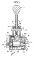
- the operation input unit 2 is comprised of an operating lever 4, a lever case (accommodating member) 5, a torque sensor (torque detector) 6, an operating knob 7, a mounting member 8 and a stopper lever 43.
- the operating lever 4 creates operational force for shifting into the range position of the automatic power transmission.
- the lever case 5 is constructed of a first case 5a and a second case 5b to internally support the operating lever 4 for rotary movement.
- the torque sensor 6 detects operational force resulting from the operating lever 4.
- the operating knob 7 is mounted to an upper end of the operating lever 4. When an operator grips the operating knob 7 and slides the operating lever 4, operational force is created.
- the mounting member 8 is mounted on a lower end of the operating lever 4.
- the torque sensor 6 is mounted to the operating lever 4 via the mounting member 8.
- the mounting member 8 is divided into an upper member and a lower member by an input shaft 6a and an output shaft 6b of the torque sensor 6. Also, the input shaft 6a and the output shaft 6b correspond to a rotary shaft of the operating lever 4.
- the stopper lever 43 prevents the operating lever 4 from moving. When the operator presses a button (not shown) of the operating knob 7, the stopper lever 43 permits the operating lever 4 to move.
- the upper member is fixedly secured to the lower end portion of the operating lever 4 and includes a lever base 9 with a cross sectional profile in a substantially U-shape.
- the lever base 9 has one end formed with a first bearing member 10.
- the first bearing member 10 has a lower central area formed with an first output shaft guide portion 11.
- the first output shaft guide portion 11 has a first bearing surface 11a formed in a semicircular arc shape for rotatably covering an upper half of the output shaft 6b.
- An outer-periphery of the first output shaft guide portion 11 is formed with an upper half of a ring mounting recess 24.
- the lever base 9 has the other end formed with a first fixture member 12.
- the first fixture member 12 has a lower central portion formed with an input shaft guide portion 13.
- the input shaft guide portion 13 covers an upper half of the input shaft 6a of the torque sensor 6.
- the lower member is comprised of a second fixture member 18 and a second bearing member 19.
- the second fixture member 18 is mounted to the first fixture member 12 so as to cover a lower half of the input shaft 6a.
- the second bearing member 19 is mounted to the first bearing member 10 so as to cover a lower half of the output shaft 6b.
- a flat portion 21 Formed on a central area of the second fixture member 18 is a flat portion 21 with which a flat portion 20 formed on a lower end of the input shaft 6a is placed in tight contact.
- the flat portion 21 forms a bottom surface of a rectangular recessed portion formed in a central area of a fixing surface 18a of the second fixture member 18.
- second threaded bores 22, 22 Formed on both ends of the second fixture member 18 are second threaded bores 22, 22. Turning screws 16, 16 into the first threaded bores 17, 17 and the second threaded bores 22, 22 allows the second fixture member 18 to be mounted to the first fixture member 12 and the input shaft 6a to be sandwiched between the first fixture member 12 and the second fixture member 18.
- the second bearing member 19 has an upper central portion formed with a second output shaft guide portion 23.
- the second output shaft guide portion 23 has a second bearing surface 23a formed in a semicircular arc shape for rotatably covering a lower half of the output shaft 6b.
- Assembling the second bearing member 19 onto the first bearing member 10 allows the second output shaft guide portion 23 to be coupled to the first bearing guide portion 11 such that the output shaft 6b is rotatably supported.
- Formed on an outer periphery of the second output shaft guide portion 23 is a lower half of a ring mounting recess 24.
- the ring member 25 has a C-shaped cross section and elasticity.
- the first bearing member 10 and the second bearing member 19 that are assembled to one another through the ring member 25 is inserted to a bush 26 that is press-fitted to the first case 5a and secured to the first case 5a.
- the torque sensor 6 includes a sensor body 27, the input shaft 6a and the output shaft 6b.
- the sensor body 27 has one end from which the input shaft 6a protrudes, and the other end from which the output shaft 6b protrudes.
- the flat portion 20 is formed on a lower end portion of the input shaft 6a.
- the output shaft 6b is disposed on the same axis with the input shaft 6a and is rotatably supported with the first bearing member 10 and the second bearing member 19. A distal end of the output shaft 6b is connected to the power assist unit 3 through a circular bore 28 formed in the first case 5a (see FIGS. 1 and 2).
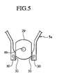
- the sensor body 27 has the other end formed with a flat board 29 that precludes the torque sensor 6 from rotation. As shown in FIG 5, the flat board 29 is sandwiched between inner walls 30, 30 of the first case 5a and, hence, the torque sensor 6 is free from being shaky in the rotational direction thereof. Also, attached to the inner walls 30, 30 are rubber members 31, 31 that preclude the torque sensor 6 from suffering from looseness resulting from distortions of the inner walls 30, 30. Sandwiching the sensor body 27 between the rubber members 31, 31 enables the torque sensor 6 to accurately and stably detect rotational torque of the operating lever 4.
- the operating lever 4 retains the torque sensor 6 by means of the mounting member 8.
- the input shaft 6a of the torque sensor 6 and the input shaft guide portion 13 are inserted to a bush 14, provided in the second case 5b, such that the operating lever 4 is rotatably supported by the second case 5b.
- the output shaft 6b of the torque sensor 6, the first bearing member 10 and the second bearing member 19 are inserted to the bush 26, provided in the first case 5a, such that the operating lever 4 is rotatably supported by the first case 5a.
- An intermediate portion of the operating lever 4 penetrates through a slide bore portion 33 formed in an upper end of the lever case 5, and the lower end portion of the operating lever 4 is accommodated inside of the lever case 5.
- a length of a circular arc of the slide bore portion 33 is designed to be equal to a range in which the operating lever 4 is available to slide.
- a slide member 35 mounted to an outer-periphery of the intermediate portion of the operating lever 4 is a slide member 35 that is slidably held in contact with an opening inner-peripheral edge 34 of the slide bore portion 33.
- the slide member 35 is comprised of a small diameter portion 35a and a large diameter portion 35b and formed in a slide sleeve in which two cylindrical portions are formed with mutually different diameters.
- An inner-peripheral surface of an upper portion of the large diameter portion 35b merges with an outer-periphery of a lower portion of the small diameter portion 35a.
- the slide member 35 is fixed to the intermediate portion of the operating lever 4.
- the upper end of the lever case 5 is formed at the position closer to the operating knob 7 than a rotational axis of the operating lever 4 (the input shaft 6a and the output shaft 6b of the torque sensor 6) so as to suppress the shakiness of the operating lever 4.
- the slide member 35 is fixed at the position closer to the operating knob 7 than a rotational axis of the operating lever 4.
- the slide member 35 is fixed with a support 36 formed at the intermediate portion of the operating lever 4.
- a diameter of the support 36 is equal to a diameter of the small diameter portion 35a.
- the guide section 37 Formed on the opening inner-peripheral edge 34 of the slide bore portion 33 is a guide section 37 that guides the slide member 35.
- the guide section 37 has a stepped cross sectional surface and is comprised of a first guide surface 37a, a second guide surface 37b and a third guide surface 37c.
- the first guide surface 37a is held in contact with an outer-peripheral surface of the small diameter portion 35a.
- the second guide surface 37b is held in contact with an outer-peripheral surface of the large diameter portion 35b.
- the third guide surface 37c is held in contact with an upper end face of the large diameter portion 35b.
- the guide section 37 is formed along the slide bore portion 33.
- the slide member 35 has a freedom to some extent in a vertical direction.
- a spring member 40 is mounted between the mounting member 8 and the bush 14.
- the spring member 40 includes a resilient member such as a wave washer.
- the spring member 40 urges the mounting member 8 toward the first case 5a. Accordingly, a margin in which the spring member 40 is compressed is effective to absorb dimensional difference between the mounting member 8 and the lever case 5, thereby the operating lever 4 and the torque sensor 6 is free from being shaky.
- the power assist unit 3 is comprised of an electric motor 31, a case 32, a gear reduction mechanism (not shown) and an output shaft OP.
- the electric motor 31 generates power assist force to be added to operational force created by the operation input device 2.
- the case 32 has a lower end to which the electric motor 31 is fixed.
- the gear reduction mechanism is accommodated in the case 32 and includes a worm wheel gear and a worm gear.
- the worm wheel gear meshes with the output shaft 6b of the torque sensor 6.
- the worm gear rotates together with a shaft of the electric motor 31 and meshes with the worm wheel gear and the operating transmission lever 42.
- the detected value of the rotational torque of the operating lever 4 increases, as operational force of the operating lever 4 increases.
- the power assist unit 3 varies a voltage applied to the electric motor 31.
- the power assist unit 3 creates rotational force of the electric motor 31 and then adds it as power assist force to operational force of the operating lever 4. Finally, output of the power assist unit 3 is applied to the output shaft OP.
- the vehicle automatic power transmission operating device 1 has features listed below.
- the first fixture member 12 and the second fixture member 18 allows the input shaft 6a of the torque sensor 6 to be fixedly secured for non-rotary movement, and the first bearing member 10 and the second bearing member 19 allows the output shaft 6b of the torque sensor 6 to be rotatably supported. Therefore, since the shakiness of the input shaft 6a in the rotational direction and axial direction thereof can be suppressed, the torque sensor 6 correctly detects operational force of the operating lever 4 and then outputs the detected value in a stable manner.
- an end portion of the sensor accommodating section is formed with an opening with a large diameter in which the torque sensor is inserted.
- the torque sensor 6 since the torque sensor 6 is assembled to the lower end portion of the operating lever 4 via the mounting member 8, the torque sensor 6 and the mounting member 8 can be assembled in a high precision and the shakiness of the torque sensor 6 can be effectively suppressed.
- the slide member 35 slides with the operating lever 4 while remaining in contact with the opening inner-peripheral edge 34, the shakiness of the operating lever 4 is suppressed. That is, since the slide member 35 is operative to bury a gap between the operating lever 4 and the slide bore portion 33, the operating lever 4 smoothly slides.
- the rotary shaft of the operating lever 4 and the bush 14 to be machined at a high precision so as to suppress the shakiness of the operating lever 4
- an expedient in which the slide member 35 is mounted to the operating lever 4 is more preferable than a method of increating the machining precision of the associated members because production cost of the vehicular automatic power transmission operating device 1 is reduced.
- a cover case which rotatably supports the output shaft of the torque sensor.
- the torque sensor can move in the axial direction of the rotary shaft of the operating lever via a splined portion by looseness between the torque sensor and the splined portion or between the case and the case cover. The above-described movement is reflected as the shakiness of the operating lever in a leftward and rightward direction (along the axial direction of the rotary shaft) thereof.
- the spring member 40 is disposed between the mounting member 8 and the bush 14, causing the operating lever 4 to be urged toward the first case 5a with constant urging force. Therefore, it becomes possible to suppress the shakiness of the operating lever 4 and the torque sensor 6 in the leftward and rightward direction thereof.
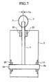
- the slide member 35 which slides along the opening inner-peripheral edge 34 while kept in contact therewith during rotary movement of the operating lever 4, is disposed closer to the operating knob 7. As shown in FIG. 7, therefore, even in the occurrence of looseness between the output shaft 6b of the torque sensor 6 and the bush 20, the shakiness of the operating lever 4 that would occur in the leftward and rightward direction thereof can be suppressed to a value of approximately L 0 . Also, even when applying an operation input unit of a short stroke for the vehicular automatic power transmission operating device 1, the operating lever 4 adequately and smoothly rotates. Therefore an operator is available to bodily sense such as a comfortable shift feeling.
- a vehicular automatic power transmission operating device 50 is comprised of an operation input unit 51, a power assist unit 52, a first cable 53 and a second cable 54.
- the operation input unit 51 is fixed through a bracket 62 to a cross car beam 61 that is disposed inside of an instrument panel compartment 60 along a vehicle widthwise direction.
- an instrument panel 59 partitions a vehicle compartment 57 and the instrument panel compartment 60.
- the operation input unit 51 creates operational force (rotational torque) for shifting into a range position of an automatic power transmission.
- the power assist unit 52 creates power assist force and then adds it to operational force.
- the first cable 53 has one end connected to the operation input unit 51 through a lower lever (operational force transfer lever) 66 and the other end connected to the power assist unit 52, thereby transferring operational force to the power assist unit 52.
- the second cable 54 transfers output of the power assist device 52 to the automatic power transmission.
- the operation input unit 51 is comprised of an operating lever 55, a lever box 56 and an operating knob 58.
- the operating lever 55 creates operational force for shifting into the range position of the automatic power transmission.
- the lever box 56 is fixed to the cross car beam 61, disposed inside of the instrument panel compartment 60, through the bracket 62 and supports the operating lever 55 for rotary movement.
- the operating knob 58 is mounted onto an upper end of the operating lever 55 and disposed in the vehicle compartment 57. When an operator grips the operating knob 58 and slides the operating lever 55, operational force is created.
- the cross car beam 61 serves as a reinforce member that forms a frame to accommodate an air conditioning unit 63 and electrical equipments in the instrument panel compartment 60 and includes a cross car beam body 61a and a support stay 61b.
- the cross car beam body 61a includes a tabular member made of steel that extends in the vehicle widthwise direction.
- the support stay 61b extends from the cross car beam body 61a toward the instrument panel 59.
- the bracket 62 is fixed to a rear side 61c of the support stay 61b (closer to the cross car beam body 61a) via bolts (fixtures) 65.
- the bracket 62 is formed with a slide recess 64 to cause the operating lever 55 to be retracted toward the instrument panel compartment 59.
- a shaft portion 71 is located at a base end portion of the operating lever 55 and is movably engaged to the slide recess 64. The shaft portion 71 slides along the slide recess 64 in secondary collision.
- a lower lever 66 is fixed to a lower end of the operating lever 55.
- the lower lever 66 has one end fixed to the lower end of the operating lever 55 and the other end (connecting portion 67) connected to the first cable 63 for rotary movement. Also, the lower lever 66 is fixed in position to be substantially perpendicular to the operating lever 55.
- the connecting portion 67 of the lower lever 66 is located below the operation input unit 51 and in an area close proximity to a vehicle front with respect to a finisher section 68 of the instrument panel 59. More particularly, the connecting portion 67 is located in a dead space 70 for ensuring a moving locus of a slide plate 69 that rotates in a forward area of the finisher section 68 accompanied by rotation of the operating lever 55.
- a position ("P" range position) of the operating lever 55 remains in a status to allow the automatic power transmission to be positioned the "P” range.
- a position (“D” range position) of the operating lever 55 indicated by a solid line, remains in a status to allow the automatic power transmission to be positioned the "D” range. Consequently, rotating the operating lever 55 from the "P" range position to the "D” range position allows the lower lever 66 to travel from the forward area of the finisher section 68 toward an area beneath the operation input unit 51, thereby pushing the first cable 53 toward the vehicle front.
- an opening portion 72 Formed in the finisher section 68 of the instrument panel 59 is an opening portion 72 that permits the operating lever 55 to rotationally move.
- the opening portion 72 is formed in a circular arc with a length L 1 .
- the slide plate 69 rotates along the opening portion 72 of the finisher section 68 during rotary movement of the operating lever 55 and closes the opening portion 72 at all times.
- a length of a circular arc of the slide plate 69 is designed to have a value greater than two times longer than the length L 1 of the circular arc of the opening portion 72.
- the operating lever 55 In the "D" range position, the operating lever 55 is positioned in the rearmost area of the vehicle. Under such a condition, the lower lever 66 is parallel to the rear side 61c of the support stay 61b and a dead space 70 is formed in the vehicle front area at the lowest end of the slide plate 69.
- the vehicular automatic power transmission operating device 50 has features listed below.
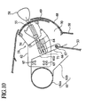
- the operating lever 55 is applied with load, the operating lever 55 is retreated into the instrument panel compartment 60 as shown in FIG. 10.
- the lower lever 66 is fixedly positioned to be substantially perpendicular to the operating lever 55 and the connecting portion 67 is located in a forward area of the finisher section 68, the lower lever 66 does not interfere with the cross car beam 61. Accordingly, since no need arises for a space to be provided to accommodate the lower lever 66 in the vicinity of a side area of the cross car beam 61, the operation input unit 51 and the instrument panel 59 can be located closer to the vehicle front.
- the instrument panel compartment 60 has the space where an operating lever 55 is moved toward the vehicle front in secondary collision, without narrowing a vehicle compartment 57.
- the operation input unit 51 is located rearward of the cross car beam body 61a of the cross car beam 61, a distance between the operation input unit 51 and the cross car beam body 61a is shortened to enable momentum of the operating lever 55 to be decreased, thereby providing a capability of increasing a rigidity of the bracket 62.
Landscapes
- Engineering & Computer Science (AREA)
- General Engineering & Computer Science (AREA)
- Mechanical Engineering (AREA)
- Arrangement Or Mounting Of Control Devices For Change-Speed Gearing (AREA)
Applications Claiming Priority (6)
| Application Number | Priority Date | Filing Date | Title |
|---|---|---|---|
| JP2003026113 | 2003-02-03 | ||
| JP2003026113A JP2004237771A (ja) | 2003-02-03 | 2003-02-03 | 車両用自動変速操作装置 |
| JP2003062162A JP2004268727A (ja) | 2003-03-07 | 2003-03-07 | 車両用自動変速操作装置 |
| JP2003062162 | 2003-03-07 | ||
| JP2003062168 | 2003-03-07 | ||
| JP2003062168A JP4002850B2 (ja) | 2003-03-07 | 2003-03-07 | 車両用自動変速操作装置 |
Publications (1)
| Publication Number | Publication Date |
|---|---|
| EP1443249A2 true EP1443249A2 (fr) | 2004-08-04 |
Family
ID=32659807
Family Applications (1)
| Application Number | Title | Priority Date | Filing Date |
|---|---|---|---|
| EP04002227A Withdrawn EP1443249A2 (fr) | 2003-02-03 | 2004-02-02 | Dispositif de commande de boíte de vitesses automatique pour véhicule |
Country Status (2)
| Country | Link |
|---|---|
| US (1) | US7237450B2 (fr) |
| EP (1) | EP1443249A2 (fr) |
Cited By (1)
| Publication number | Priority date | Publication date | Assignee | Title |
|---|---|---|---|---|
| EP1693603A3 (fr) * | 2005-02-22 | 2007-07-11 | FUJI KIKO Co., Ltd. | Dispositif de levier de changement de vitesses pour véhicule |
Families Citing this family (8)
| Publication number | Priority date | Publication date | Assignee | Title |
|---|---|---|---|---|
| EP1640641A2 (fr) * | 2004-09-24 | 2006-03-29 | Calsonic Kansei Corporation | Boîte de vitesses automatiques pour véhicule |
| US8453772B2 (en) | 2005-08-01 | 2013-06-04 | Albert W. Brown | Manually operated electrical control and installation scheme for electric hybrid vehicles |
| US7648001B2 (en) * | 2005-09-13 | 2010-01-19 | Kubota Corporation | Speed shift arrangement for work vehicle |
| US8215196B2 (en) * | 2007-04-27 | 2012-07-10 | Mccoy Corporation | Tong gear shift system |
| DE102008015874A1 (de) * | 2008-03-26 | 2009-10-01 | Lemförder Electronic GmbH | Betätigungseinrichtung mit Haptikemulation |
| KR100999262B1 (ko) * | 2008-09-29 | 2010-12-07 | 현대자동차주식회사 | 변속레버 충격저감장치 |
| US10144483B2 (en) | 2011-08-01 | 2018-12-04 | Shimano Inc. | Bicycle component control device |
| KR101534930B1 (ko) * | 2013-10-17 | 2015-07-27 | 현대자동차주식회사 | 자동변속기 차량용 변속레버 조립체 및 이의 조립방법 |
Citations (1)
| Publication number | Priority date | Publication date | Assignee | Title |
|---|---|---|---|---|
| JPH11286225A (ja) | 1998-01-16 | 1999-10-19 | Luk Getriebe Syst Gmbh | 手動切替用サ―ボ支援装置 |
Family Cites Families (5)
| Publication number | Priority date | Publication date | Assignee | Title |
|---|---|---|---|---|
| US2323878A (en) * | 1940-03-06 | 1943-07-06 | Elmer G Kesling | Gear shifting mechanism |
| US5002166A (en) * | 1989-09-14 | 1991-03-26 | Automotive Products Plc | Dual mode motor vehicle clutch control system |
| US5083647A (en) * | 1991-01-24 | 1992-01-28 | Ford New Holland, Inc. | Method of controlling clutches |
| US5928106A (en) * | 1997-10-16 | 1999-07-27 | Navistar International Transportation Corp | Electro-hydraulic clutch actuation system for manual transmission |
| JP3440200B2 (ja) | 1998-03-31 | 2003-08-25 | 富士機工株式会社 | 車両用変速機操作装置 |
-
2004
- 2004-02-02 EP EP04002227A patent/EP1443249A2/fr not_active Withdrawn
- 2004-02-02 US US10/768,706 patent/US7237450B2/en not_active Expired - Fee Related
Patent Citations (1)
| Publication number | Priority date | Publication date | Assignee | Title |
|---|---|---|---|---|
| JPH11286225A (ja) | 1998-01-16 | 1999-10-19 | Luk Getriebe Syst Gmbh | 手動切替用サ―ボ支援装置 |
Cited By (1)
| Publication number | Priority date | Publication date | Assignee | Title |
|---|---|---|---|---|
| EP1693603A3 (fr) * | 2005-02-22 | 2007-07-11 | FUJI KIKO Co., Ltd. | Dispositif de levier de changement de vitesses pour véhicule |
Also Published As
| Publication number | Publication date |
|---|---|
| US20040211617A1 (en) | 2004-10-28 |
| US7237450B2 (en) | 2007-07-03 |
Similar Documents
| Publication | Publication Date | Title |
|---|---|---|
| US5240284A (en) | Steering column assembly with horizontal position adjustment mechanism | |
| JP4002849B2 (ja) | 車両用自動変速操作装置の操作レバー構造 | |
| JP5225937B2 (ja) | 自動変速機のシフト装置 | |
| US20060060019A1 (en) | Vehicular automatic transmission and automatic selector thereof | |
| US7237450B2 (en) | Vehicular automatic power transmission operating device | |
| US9540034B2 (en) | Steering apparatus | |
| US7641164B2 (en) | Power seat slide apparatus for vehicle | |
| CN116767336B (zh) | 转向装置 | |
| EP1738953B1 (fr) | Glissière pour siège de véhicule | |
| KR20190083763A (ko) | 차량용 슬라이딩 기어박스 | |
| WO2010026680A1 (fr) | Dispositif de panneau de moniteur | |
| US6619155B2 (en) | Adjustable pedal apparatus | |
| JP3522627B2 (ja) | シートスライド装置 | |
| JP2010105622A (ja) | 操作位置検出装置及びシフト操作位置検出装置 | |
| KR20220049935A (ko) | 차량용 칵핏모듈 조립체 | |
| JP2009196388A (ja) | 電動チルト式ステアリング装置 | |
| US6167772B1 (en) | Arrangement for attaching gearshift assembly and method of assembling the same | |
| JP2022145498A (ja) | ステアリング装置 | |
| JP4014929B2 (ja) | ペダル後退量抑制装置 | |
| JP4313642B2 (ja) | シフトレバー装置及びシフトレバー装置の取り付け構造 | |
| EP0402133A1 (fr) | Ensemble de colonnes de direction avec mécanisme de réglage de la position horizontale | |
| JP7294077B2 (ja) | ステアリング装置 | |
| JP7279618B2 (ja) | ステアリング装置 | |
| JP4741763B2 (ja) | シフト操作装置における異音発生防止機構 | |
| JP2001105922A (ja) | 変速機の操作装置 |
Legal Events
| Date | Code | Title | Description |
|---|---|---|---|
| PUAI | Public reference made under article 153(3) epc to a published international application that has entered the european phase |
Free format text: ORIGINAL CODE: 0009012 |
|
| AK | Designated contracting states |
Kind code of ref document: A2 Designated state(s): AT BE BG CH CY CZ DE DK EE ES FI FR GB GR HU IE IT LI LU MC NL PT RO SE SI SK TR |
|
| AX | Request for extension of the european patent |
Extension state: AL LT LV MK |
|
| STAA | Information on the status of an ep patent application or granted ep patent |
Free format text: STATUS: THE APPLICATION HAS BEEN WITHDRAWN |
|
| 18W | Application withdrawn |
Effective date: 20091102 |