EP1443422A1 - Informationsverarbeitungsvorrichtung und informationsverarbeitungsverfahren - Google Patents
Informationsverarbeitungsvorrichtung und informationsverarbeitungsverfahren Download PDFInfo
- Publication number
- EP1443422A1 EP1443422A1 EP02802731A EP02802731A EP1443422A1 EP 1443422 A1 EP1443422 A1 EP 1443422A1 EP 02802731 A EP02802731 A EP 02802731A EP 02802731 A EP02802731 A EP 02802731A EP 1443422 A1 EP1443422 A1 EP 1443422A1
- Authority
- EP
- European Patent Office
- Prior art keywords
- recording
- predetermined data
- recorded
- processing apparatus
- information processing
- Prior art date
- Legal status (The legal status is an assumption and is not a legal conclusion. Google has not performed a legal analysis and makes no representation as to the accuracy of the status listed.)
- Granted
Links
Images










Classifications
-
- G—PHYSICS
- G06—COMPUTING OR CALCULATING; COUNTING
- G06Q—INFORMATION AND COMMUNICATION TECHNOLOGY [ICT] SPECIALLY ADAPTED FOR ADMINISTRATIVE, COMMERCIAL, FINANCIAL, MANAGERIAL OR SUPERVISORY PURPOSES; SYSTEMS OR METHODS SPECIALLY ADAPTED FOR ADMINISTRATIVE, COMMERCIAL, FINANCIAL, MANAGERIAL OR SUPERVISORY PURPOSES, NOT OTHERWISE PROVIDED FOR
- G06Q50/00—Information and communication technology [ICT] specially adapted for implementation of business processes of specific business sectors, e.g. utilities or tourism
- G06Q50/10—Services
-
- G—PHYSICS
- G06—COMPUTING OR CALCULATING; COUNTING
- G06F—ELECTRIC DIGITAL DATA PROCESSING
- G06F16/00—Information retrieval; Database structures therefor; File system structures therefor
- G06F16/60—Information retrieval; Database structures therefor; File system structures therefor of audio data
- G06F16/63—Querying
- G06F16/635—Filtering based on additional data, e.g. user or group profiles
-
- G—PHYSICS
- G06—COMPUTING OR CALCULATING; COUNTING
- G06F—ELECTRIC DIGITAL DATA PROCESSING
- G06F16/00—Information retrieval; Database structures therefor; File system structures therefor
- G06F16/60—Information retrieval; Database structures therefor; File system structures therefor of audio data
- G06F16/64—Browsing; Visualisation therefor
Definitions
- the jog dial 23 is fixed between a key A and a key B disposed at the right side of the keyboard 24 in Fig. 4 on the main unit 21 such that the top surface of the jog dial 23 is almost flush with the key A and the key B.
- the jog dial 23 performs predetermined processing (for example, scrolling the screen) in response to a rotating operation of the dial 23 indicated by the arrow a in Fig. 5, and performs predetermined processing (for example, setting the selection of the icon) in response to a shifting operation of the jog dial 23 indicated by the arrow b in Fig. 5.
- the jog-dial state monitor program 54C also detects an event of the jog dial 23 (for example, the rotation of the jog dial 23 in the direction indicated by the arrow a in Fig. 5 or the pressing of the jog dial 23 in the direction indicated by the arrow b in Fig. 5), and performs processing according to the detected event.
- the jog-dial driver 54D implements various functions in accordance with the operations of the jog dial 23.
- the HDD 67 is connected to the primary IDE controller via the IDE bus 62.
- IDE device such as a CD ROM drive or an HDD (not shown)
- the connected IDE device is electrically connected to the secondary IDE controller.
- the e-mail program 67A, the auto-pilot program 67B, the jog-dial state monitor program 67C, the jog-dial driver 67D, the OS 67E, the communication program 67F, the web browser 67G, and the other application programs 67H recorded in the HDD 67 are loaded in the RAM 54.
- the I/O interface 69 is also connected to the ISA/EIO bus 63.
- the I/O interface 69 is formed of an embedded controller, in which a ROM 70, a RAM 71, and a CPU 72 are interconnected to each other.
- the ROM 70 stores an IEEE1394 interface program 70A, an LED control program 70B, a touch-pad input monitor program 70C, a key-input monitor program 70D, a wake-up program 70E, and a jog-dial state monitor program 70F.
- the RAM 71 contains an LED control register, a touch-pad input status register, a key-input status register, a time setting register, a jog-dial state monitor I/O register, an IEEE1394 I/F register, etc. as registers 71A through 71F.
- a predetermined value is stored in the LED control register, and the switching of the message lamp ML is controlled in accordance with the stored value.
- a predetermined operation key flag is stored in the key-input status register.
- a predetermined time is set in the time setting register in response to the operation performed on the keyboard 24 by the user.
- the memory stick 131 is one type of flash memory card developed by Sony Corporation, which is the assignee of the present application.
- the memory stick 131 stores therein a non-volatile flash memory device, which is one type of EEPROM (Electrically Erasable and Programmable Read Only Memory), in a 21.5 (width) ⁇ 50 (length) ⁇ 2.8 (thickness) [mm] small and thin plastic casing.
- EEPROM Electrical Erasable and Programmable Read Only Memory
- the memory stick 131 is able to read and write various data, such as images, audio, and music, via 10 pin terminals.
- the memory stick 131 employs a unique serial protocol that ensures the compatibility in a device in which the memory stick 131 is used even if the specifications of the built-in flash memory are changed in response to an increased capacity.
- High-speed performance such as the maximum writing speed of 1.5 [MB/S] and the maximum reading speed 2.45 [MB/S], is implemented, and high reliability is guaranteed by the provision of an erroneous-erasing preventing switch.
- the PDA 11 is connected to the cradle 141, as shown in Fig. 9, so that the bottom surface of the PDA 11 is in contact with the top surface of the cradle 141.
- a USB (Universal Serial Bus) port (not shown), which is connected to the cradle 141, is provided on the bottom surface of the PDA 11.
- the cradle 141 is a docking station for allowing the PDA 11 to send and receive information to and from the personal computer 1 by being connected to the personal computer 1 by wired connection so as to update the data of the PDA 11 and the personal computer 1 (to synchronize data by hot sync).
- the PDA 11 is provided with a display unit 161, keys 162, and a jog dial 151.
- the display unit 161 is formed of a thin display portion, such as a liquid crystal display device, and displays images, such as icons, thumbnails, and text (for example, a predetermined GUI (Graphic User Interface) for assisting user's operations when a client program, which is described below, is run).
- a touch pad is provided at the upper portion of the display unit 161. By pressing the touch pad with a finger or a pen, predetermined data or an operation instruction is input into the PDA 11.
- the keys 162 are formed of input keys, which are used for selecting an icon or a thumbnail displayed on the display unit 161.
- the jog dial 151 is operated for selecting an icon or a thumbnail displayed on the display unit 161 in accordance with a rotation operation of the jog dial 151 or a pressing operation toward the main unit.
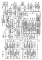
- a CPU (Central Processing Unit) 171 runs an operating system or various programs, such as developed application programs (for example, the client program, which is discussed below) stored in a Flash ROM (Read Only Memory) 173 or an EDO DRAM (Extended Data Out Dynamic Random Access Memory) 174 in synchronization with a clock signal supplied from an oscillator 172.
- a Flash ROM Read Only Memory
- EDO DRAM Extended Data Out Dynamic Random Access Memory
- the Flash ROM 173 is formed of a flash memory, which is one type of EEPROM (Electrically Erasable Programmable Read Only Memory), and basically stores programs used by the CPU 171 and fixed data of computation parameters.
- the EDO DRAM 174 stores programs used by the CPU 171 and variable parameters used during the execution of the programs.
- a memory stick interface 175 reads data from the memory stick 131 loaded in the PDA 11, and also writes data supplied from the PDA 171 to the memory stick 131.
- a USB (Universal Serial Bus) interface 176 receives data or programs from a drive 183, which is a USB device connected to the PDA 11, and also supplies data from the CPU 171 to the drive 183 in synchronization with a clock signal supplied from an oscillator 177.
- the USB interface 176 receives data or programs from the cradle 141, which is a USB device connected to the PDA 11, and also supplies data from the CPU 171 to the cradle 141 in synchronization with a clock signal supplied from the oscillator 177.
- the drive 183 is also connected to the USB interface 176.
- the drive 183 reads data or a program recorded in a magnetic disk 191, an optical disc 192, a magneto-optical disk 193, or a semiconductor memory 194 loaded in the drive 183, and supplies the data or the program to the CPU 171 or the EDO DRAM 174 via the USB interface 176.
- the drive 183 also records data or a program supplied from the CPU 171 to the magnetic disk 191, the optical disc 192, the magneto-optical disk 193, or the semiconductor memory 194 loaded in the drive 183.
- the Flash ROM 173, the EDO DRAM 174, the memory stick interface 175, and the USB interface 176 are connected to the CPU 171 via an address bus and a data bus.
- the display unit 161 receives data from the CPU 171 via an LCD bus, and displays images or characters corresponding to the received data.
- the display unit 161 displays a predetermined GUI for assisting the user's operation when the client program, which is discussed below, is run.
- a touch pad controller 178 receives data (indicating, for example, touched coordinates) corresponding to the operation from the display unit 161, and supplies a signal corresponding to the received data to the CPU 171 via a serial bus.
- An EL (Electro Luminescence) driver 179 operates electric-field emitting devices disposed at the rear side of the liquid crystal display of the display unit 161 so as to control the brightness of the display unit 161.
- An infrared communication unit 180-1 sends data received from the CPU 171 to another device (for example, a different PDA) via a UART (Universal asynchronous receiver transmitter) by means of an infrared, and also receives data sent from another device by means of an infrared and supplies the data to the CPU 171.
- another device for example, a different PDA
- UART Universal asynchronous receiver transmitter
- a communication unit 180-2 sends data received from the CPU 171 to another device (for example, the personal computer 1) according to a predetermined communication method, such as IEEE802.11a, infrared communication, or Bluetooth, and also receives data of a predetermined communication method sent from another device and supplies the data to the CPU 171.
- a predetermined communication method such as IEEE802.11a, infrared communication, or Bluetooth
- the PDA 11 is able to communicate with other devices via the UART by means of an infrared, or by using a different wireless communication method.
- the communication unit 180-1 and the communication unit 180-2 are hereinafter simply referred to as the "communication unit 180" unless it is necessary to distinguish them.
- An audio playback unit 182 is formed of, for example, a speaker and a decoder circuit for audio data.
- the audio playback unit 182 decodes music data received from the personal computer 1 and plays it back to output the sound.
- the audio playback unit 182 plays back audio data supplied from the CPU 171 via a buffer 181, and outputs the sound corresponding to the data.
- the jog dial 151 supplies data in accordance with a rotation operation or a pressing operation toward the main unit to the CPU 171.
- the display unit 202 includes a transceiver antenna 205, disposed at the upper left of the display unit 202, which can be pulled and pushed from and into the display unit 202.
- the cellular telephone 12 sends and receives radio waves via the antenna 205 to and from one of the base stations, which are fixed wireless stations.
- a liquid crystal display 209 is provided on the front surface of the display unit 202.
- the liquid crystal display 209 displays the radio reception state, the remaining amount of battery, the names and telephone numbers of communicating parties, which are registered in a telephone directory, the transmission log, e-mail messages, simplified homepages, images captured by a CCD camera 207 of a camera unit 206, which are discussed below, and predetermined GUIs for assisting the user's operation when the client program, which is discussed below, is started.
- a memo button 211 and a microphone 212 are provided below the operation keys 210 of the main unit 203.
- the cellular telephone 12 records the voice of a communicating party.
- the cellular telephone 12 collects user's voice by using the microphone 212.
- the main unit 203 selects a desired telephone number from a plurality of telephone numbers of a telephone directory list displayed on the liquid crystal display 209 in accordance with the rotation operation of the jog dial 213 by the user, and when the jog dial 213 is pressed toward the main unit 203, the main unit 203 sets the selected telephone number and automatically calls the set telephone number.
- the display unit 202 may also be provided with the camera unit 206 that is rotatable within the angle of almost 180 degrees at the top center of the display unit 202 (the provision of the camera unit 206 is not essential).
- the cellular telephone 12 is able to capture a desired subject by using the CCD camera 207 of the camera unit 206.
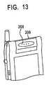
- a speaker 208 disposed at the rear center of the camera unit 206 faces the user, as shown in Fig. 13. Then, the cellular telephone 12 is switched to the normal audio communication mode.
- Fig. 14 is a block diagram illustrating the internal configuration of the cellular telephone 12. A description is given below, assuming that the cellular telephone 12 is provided with the camera unit 206. However, the provision of the camera unit 206 is not essential.
- a main controller 251 for centrally controlling the display unit 202 and the main unit 203 is connected via a main bus 261 to a power source circuit 252, an operation input controller 253, an image encoder 254, a camera I/F (interface) 255, an LCD (Liquid Crystal Display) controller 256, a multiplexer/demultiplexer 258, a modulation/demodulation circuit 259, and an audio codec 260.
- the main controller 251 is also connected via a synchronous bus 262 to the image encoder 254, an image decoder 257, the multiplexer/demultiplexer 258, a storage playback unit 263, the modulation/demodulation circuit 259, and the audio codec 260.
- the cellular telephone 12 In the audio communication mode, the cellular telephone 12 also amplifies a signal received by the antenna 205 in the transceiver circuit 264 so as to perform frequency conversion and analog-to-digital conversion on the received signal. The cellular telephone 12 then performs de-spread spectrum on the digital signal in the modulation/demodulation circuit 259, and converts the digital signal into an analog audio signal in the audio codec 260. The cellular telephone 12 then controls the speaker 208 to output the sound corresponding to the analog audio signal.
- the main controller 251 performs spread spectrum on the text data by using the modulation/demodulation circuit 259, performs digital-to-analog conversion and frequency conversion on the text data by using the transceiver circuit 264, and then, transmits the text data to a base station via the antenna 205.
- image data captured by the CCD camera 207 is supplied to the image encoder 254 via the camera interface 255.
- the multiplexer/demultiplexer 258 demultiplexes the multiplexed data into the coded image data and the audio data, and supplies the coded image data to the image decoder 257 via the synchronous bus 262 and supplies the audio data to the audio codec 260 via the synchronous bus 262.
- the cellular telephone 12 is also able to record various application programs (for example, the client program, which is described below) in the RAM or the ROM of the main controller 251, which is formed of the CPU, the ROM, and the RAM, and executes the programs by using the CPU.
- various application programs for example, the client program, which is described below
- the main controller 251 which is formed of the CPU, the ROM, and the RAM
- the modulation/demodulation circuit 259 When the client program, which is discussed below, is run by the main controller 251, as in the data communication mode, the modulation/demodulation circuit 259 performs spread spectrum on a request signal sent to the personal computer 1, and the transceiver circuit 264 performs digital-to-analog conversion and frequency conversion on the signal. The resulting signal is then transmitted via the antenna 205. Also, as in the data communication mode, music data sent from the personal computer 1 is received by the antenna 205, and the transceiver circuit 264 amplifies the music data and performs frequency conversion and analog-to-digital conversion on the music data. The modulation/demodulation circuit 259 then performs de-spread spectrum on the music data, and the audio codec 260 converts the music data into an analog audio signal. The sound corresponding to the music data converted into the analog audio signal is then output from the speaker 208.
- a communication unit that is able to perform wireless communication according to a predetermined communication method, for example, IEEE802.11a, infrared communication, or Bluetooth, may be provided to perform wireless communication with the personal computer 1 according to a method different from the data communication mode.
- a predetermined communication method for example, IEEE802.11a, infrared communication, or Bluetooth
- Fig. 15B is a side view of the desk-top playback device 13.
- the desk-top playback device 13 is formed to be very thin, as shown in Fig. 15B, which increases the flexibility to select the installation place though the size of the display panel 281 is sufficiently large.
- Fig. 16 is a block diagram illustrating the configuration of the desk-top playback device 13.
- An input IF (Interface) 301 receives a signal indicating a user's operation from the operation button 283 or an IR receiver 303 which has received an infrared signal from a remote commander 302, and outputs the signal to a controller 305 via a bus 304.
- the display controller 307 outputs image data to the display panel 281, and controls the image data to be displayed under the control of the controller 305.
- the audio output unit 308 plays back input audio data based on the format, outputs the audio data to the speaker 284 or the headphone 309, and controls the sound to be output.
- a GUI screen for assisting the user's operation is displayed on a display panel 351. Since the display area of the display panel 351 is much smaller than the display panel 281 of the desk-top playback device 13 described with reference to Figs. 15A and 15B, a simple GUI may be displayed compared to the GUI displayed on the display panel 281 of the desk-top playback device 13.
- the portable playback device 14 is provided with cursor keys 352 and 353, a zoom-out key 354, a zoom-in key 355, and a restart key 356.
- a remote commander 357 provided with keys similar to the cursor keys 352 and 353, the zoom-out key 354, the zoom-in key 355, and the restart key 356 is also provided in a mid portion of a cable for connecting the portable playback device 14 to a headphone 16 so as to allow the user to operate the portable playback device 14 while keeping it in a pocket or a bag.
- the user operates the cursor keys 352 and 353, the zoom-out key 354, the zoom-in key 355, or the restart key 356 by referring to the GUI displayed on a display panel 351, or operates the remote commander 357 without referring to the display panel 351.
- the communication unit 386 performs wireless communication with the personal computer 1 according to a predetermined communication method, for example, IEEE802.11a, infrared communication, or Bluetooth.
- the communication unit 386 sends a music-data request signal input from the controller 381 via the bus 382 to the personal computer 1, and receives music data from the personal computer 1 and outputs it to the controller 381 via the bus 382.
- the user is able to randomly listen to music by changing the position of the needle, and if there is a piece of music that pleases the user, the user can operate the restart button 374 to listen to that piece of music from the beginning.
- step S36 the client program 421 sends a request to restart music that is currently played back from the beginning to the server 401 via the communication unit 423. Then, the server program 411 of the server 401 sends the whole music data to the client 402 based on the received request.
- the server program 411 analyzes the content of the request received from the client 402. More specifically, the server program 411 extracts information required for updating the link information database 416 or the ranking information database 417, such as the requested music piece ID, the time at which the request was made (or the day of the week or the date), or whether the request is for restarting the music piece from the beginning.
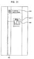
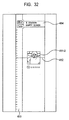
- the client 402 that can display thumbnails 451-1 and 451-2 shown in Figs. 31 and 32 (for example, the client 402 that can display relatively large GUIs, such as the PDA 11 or the desk-top playback device 13), information indicating the types of thumbnails in a certain station or a certain hierarchical category, or if necessary, image data corresponding to thumbnails, is sent according to the updating content of the databases.
- the server 401 is able to search for music data in response to a request signal from the client 402 and sends the music data.
- the server 401 is also able to update the link information database 416 and the ranking information database 417 by reflecting favorite information of the users of a plurality of clients 402.
- icons 481-1 and 481-2 indicating different stations or icons 482-1 and 482-2 indicating different hierarchical categories may be selected in the same level of the icons 461-1 through 461-6 corresponding to the music data.
- Steps forming the program recorded in a recording medium may be performed in a time-series manner in chronological order described in this specification. Alternatively, they may be performed concurrently or individually.
Landscapes
- Engineering & Computer Science (AREA)
- Theoretical Computer Science (AREA)
- Multimedia (AREA)
- General Physics & Mathematics (AREA)
- Physics & Mathematics (AREA)
- General Engineering & Computer Science (AREA)
- Databases & Information Systems (AREA)
- Data Mining & Analysis (AREA)
- Business, Economics & Management (AREA)
- Tourism & Hospitality (AREA)
- Human Resources & Organizations (AREA)
- General Business, Economics & Management (AREA)
- Strategic Management (AREA)
- Primary Health Care (AREA)
- Marketing (AREA)
- General Health & Medical Sciences (AREA)
- Economics (AREA)
- Health & Medical Sciences (AREA)
- Reverberation, Karaoke And Other Acoustics (AREA)
- Information Retrieval, Db Structures And Fs Structures Therefor (AREA)
- Management Or Editing Of Information On Record Carriers (AREA)
- Mobile Radio Communication Systems (AREA)
Applications Claiming Priority (3)
| Application Number | Priority Date | Filing Date | Title |
|---|---|---|---|
| JP2001344396 | 2001-11-09 | ||
| JP2001344396A JP3731525B2 (ja) | 2001-11-09 | 2001-11-09 | 情報処理装置および情報処理方法、情報処理システム、並びにプログラム |
| PCT/JP2002/011641 WO2003040959A1 (fr) | 2001-11-09 | 2002-11-08 | Appareil de traitement d'informations et procede de traitement d'informations |
Publications (3)
| Publication Number | Publication Date |
|---|---|
| EP1443422A1 true EP1443422A1 (de) | 2004-08-04 |
| EP1443422A4 EP1443422A4 (de) | 2005-06-01 |
| EP1443422B1 EP1443422B1 (de) | 2018-08-15 |
Family
ID=19157933
Family Applications (1)
| Application Number | Title | Priority Date | Filing Date |
|---|---|---|---|
| EP02802731.6A Expired - Lifetime EP1443422B1 (de) | 2001-11-09 | 2002-11-08 | Informationsverarbeitungsvorrichtung und informationsverarbeitungsverfahren |
Country Status (5)
| Country | Link |
|---|---|
| US (2) | US7330874B2 (de) |
| EP (1) | EP1443422B1 (de) |
| JP (1) | JP3731525B2 (de) |
| KR (1) | KR101002996B1 (de) |
| WO (1) | WO2003040959A1 (de) |
Cited By (1)
| Publication number | Priority date | Publication date | Assignee | Title |
|---|---|---|---|---|
| EP1845665A3 (de) * | 2006-03-06 | 2008-08-06 | Denso Corporation | Elektronische Steuereinheit mit mehreren Regelkreisen |
Families Citing this family (30)
| Publication number | Priority date | Publication date | Assignee | Title |
|---|---|---|---|---|
| JP2002268905A (ja) * | 2001-03-07 | 2002-09-20 | Canon Inc | プログラム動作装置、プログラム書込制御装置、プログラム書込制御方法及び記憶媒体 |
| JP4088749B2 (ja) | 2001-11-09 | 2008-05-21 | ソニー株式会社 | 情報処理装置および情報処理方法、並びにプログラム |
| JP3731525B2 (ja) | 2001-11-09 | 2006-01-05 | ソニー株式会社 | 情報処理装置および情報処理方法、情報処理システム、並びにプログラム |
| JP4617167B2 (ja) * | 2004-02-04 | 2011-01-19 | キヤノン株式会社 | 放送受信装置及びその制御方法 |
| JP4295644B2 (ja) * | 2004-03-08 | 2009-07-15 | 京セラ株式会社 | 携帯端末及び携帯端末の放送記録再生方法並びに放送記録再生プログラム |
| US7492023B2 (en) * | 2004-03-26 | 2009-02-17 | Fujifilm Corporation | Solid state imaging device |
| JP2006155782A (ja) * | 2004-11-30 | 2006-06-15 | Sony Corp | 記録装置、再生装置、画像ファイル生成方法、表示制御方法 |
| US7631352B1 (en) * | 2005-06-15 | 2009-12-08 | Daniel John Nelson | Link2File automated computer location and linking system |
| KR101147215B1 (ko) | 2005-10-04 | 2012-05-25 | 삼성전자주식회사 | Dlna 홈 네트워크 및 dlna 홈 네트워크에서의 썸네일 관리 방법 |
| JP4846334B2 (ja) * | 2005-10-17 | 2011-12-28 | 三菱電機株式会社 | 音楽再生装置 |
| US7640041B2 (en) * | 2005-11-30 | 2009-12-29 | Freescale Semiconductor, Inc. | Multiple function handheld device |
| KR100782825B1 (ko) * | 2005-12-01 | 2007-12-06 | 삼성전자주식회사 | 오디오 컨텐츠 선택 정보 제공 방법 및 장치와 그 방법을수행하는 프로그램이 기록된 기록매체 |
| JP4894252B2 (ja) | 2005-12-09 | 2012-03-14 | ソニー株式会社 | データ表示装置、データ表示方法及びデータ表示プログラム |
| JP4437548B2 (ja) | 2005-12-09 | 2010-03-24 | ソニー株式会社 | 音楽コンテンツ表示装置、音楽コンテンツ表示方法及び音楽コンテンツ表示プログラム |
| US7970835B2 (en) * | 2006-04-04 | 2011-06-28 | Xerox Corporation | Peer-to-peer file sharing system and method using downloadable data segments |
| US20080125889A1 (en) * | 2006-08-22 | 2008-05-29 | William Edward Atherton | Method and system for customization of entertainment selections in response to user feedback |
| US8564544B2 (en) * | 2006-09-06 | 2013-10-22 | Apple Inc. | Touch screen device, method, and graphical user interface for customizing display of content category icons |
| US9304675B2 (en) | 2006-09-06 | 2016-04-05 | Apple Inc. | Portable electronic device for instant messaging |
| GB2444974B (en) * | 2006-12-22 | 2011-12-28 | British Sky Broadcasting Ltd | Media device and interface |
| US8689132B2 (en) | 2007-01-07 | 2014-04-01 | Apple Inc. | Portable electronic device, method, and graphical user interface for displaying electronic documents and lists |
| KR101366315B1 (ko) * | 2007-01-19 | 2014-02-20 | 엘지전자 주식회사 | 이동통신 단말기에서 단축 폴더 설정방법, 이동통신단말기에서 컨텐츠 재생 방법 그리고 이동통신 단말기 |
| US20080239888A1 (en) * | 2007-03-26 | 2008-10-02 | Yamaha Corporation | Music Data Providing System |
| US20090092266A1 (en) * | 2007-10-04 | 2009-04-09 | Cheng-Chieh Wu | Wireless audio system capable of receiving commands or voice input |
| JP5094341B2 (ja) * | 2007-11-16 | 2012-12-12 | キヤノン株式会社 | 情報処理装置及び情報処理方法 |
| KR101439549B1 (ko) | 2008-04-07 | 2014-11-03 | 엘지전자 주식회사 | 탐색화면 제공 장치 및 방법 |
| EP2282697B1 (de) * | 2008-06-02 | 2016-12-14 | DENTSPLY International Inc. | Verfahren zur konzeption einer massgeschneiderten zahnprothese mithilfe digitaler patientenbilder |
| WO2009155463A2 (en) * | 2008-06-20 | 2009-12-23 | Leostream Corp | Management layer method and apparatus for dynamic assignment of users to computer resources |
| US8698648B2 (en) * | 2009-01-09 | 2014-04-15 | General Electric Company | Methods and systems of simultaneously communicating utility data and voice data |
| US10666726B2 (en) * | 2012-05-08 | 2020-05-26 | Wingarc1St Inc. | Data processing system, and program for managing data |
| US11194467B2 (en) | 2019-06-01 | 2021-12-07 | Apple Inc. | Keyboard management user interfaces |
Family Cites Families (40)
| Publication number | Priority date | Publication date | Assignee | Title |
|---|---|---|---|---|
| JPH0828043B2 (ja) | 1989-12-28 | 1996-03-21 | アルパイン株式会社 | オーディオ機器の再生方法 |
| JP3203069B2 (ja) | 1992-11-05 | 2001-08-27 | 出光石油化学株式会社 | 位相差補償フィルムおよびその製造方法 |
| GB2278258A (en) * | 1993-05-17 | 1994-11-23 | Ibm | Token ring network |
| JPH07250316A (ja) | 1994-03-14 | 1995-09-26 | Brother Ind Ltd | データ伝送装置 |
| US5940610A (en) * | 1995-10-05 | 1999-08-17 | Brooktree Corporation | Using prioritized interrupt callback routines to process different types of multimedia information |
| JP2956569B2 (ja) | 1996-02-26 | 1999-10-04 | ヤマハ株式会社 | カラオケ装置 |
| JP3744046B2 (ja) | 1996-03-04 | 2006-02-08 | ヤマハ株式会社 | カラオケ装置 |
| JPH1063281A (ja) | 1996-08-23 | 1998-03-06 | Ado Commun:Kk | 音響映像装置及びこれを用いた楽曲のアレンジ方法 |
| JPH10208444A (ja) * | 1997-01-28 | 1998-08-07 | Sony Corp | 音楽データ管理装置 |
| JP3064949B2 (ja) | 1997-04-02 | 2000-07-12 | 株式会社ケイ | 擁壁用ブロックの製造方法及び擁壁施工方法 |
| US6363411B1 (en) * | 1998-08-05 | 2002-03-26 | Mci Worldcom, Inc. | Intelligent network |
| US6385596B1 (en) * | 1998-02-06 | 2002-05-07 | Liquid Audio, Inc. | Secure online music distribution system |
| CN1128542C (zh) * | 1998-04-03 | 2003-11-19 | 松下电器产业株式会社 | 便携式视听系统 |
| US6337856B1 (en) * | 1998-05-20 | 2002-01-08 | Steelcase Development Corporation | Multimedia data communications system |
| JP3709086B2 (ja) * | 1998-12-16 | 2005-10-19 | 株式会社日立製作所 | ブレーキ制御装置 |
| US6643620B1 (en) * | 1999-03-15 | 2003-11-04 | Matsushita Electric Industrial Co., Ltd. | Voice activated controller for recording and retrieving audio/video programs |
| US20020118954A1 (en) * | 2001-12-07 | 2002-08-29 | Barton James M. | Data storage management and scheduling system |
| JP2001054096A (ja) * | 1999-08-06 | 2001-02-23 | Sony Corp | 送信装置および方法、受信装置および方法、配信システム、並びに媒体 |
| WO2001018630A2 (en) * | 1999-09-09 | 2001-03-15 | Percussion Software, Inc. | Xml dynamic content retrieval using style and content definition sheets |
| JP4337185B2 (ja) | 1999-10-08 | 2009-09-30 | ソニー株式会社 | 携帯型電話装置 |
| GB2356732B (en) * | 1999-11-26 | 2003-12-10 | Sony Uk Ltd | Editing of recorded material |
| WO2001042900A2 (en) * | 1999-12-08 | 2001-06-14 | Tune To Com Inc. | Scheduled retrieval, storage and access of media data |
| US6826173B1 (en) * | 1999-12-30 | 2004-11-30 | At&T Corp. | Enhanced subscriber IP alerting |
| US6248946B1 (en) * | 2000-03-01 | 2001-06-19 | Ijockey, Inc. | Multimedia content delivery system and method |
| JP2001297093A (ja) | 2000-04-14 | 2001-10-26 | Alpine Electronics Inc | 音楽配給システムおよびサーバ装置 |
| EP1170882B1 (de) * | 2000-07-07 | 2006-09-06 | Hitachi, Ltd. | Basisstationsgerät, mobile Station, und Inhaltversorger |
| US20020143960A1 (en) * | 2000-08-02 | 2002-10-03 | Erez Goren | Virtual network generation system and method |
| US7779097B2 (en) * | 2000-09-07 | 2010-08-17 | Sonic Solutions | Methods and systems for use in network management of content |
| US20020092019A1 (en) * | 2000-09-08 | 2002-07-11 | Dwight Marcus | Method and apparatus for creation, distribution, assembly and verification of media |
| WO2002025460A1 (en) * | 2000-09-19 | 2002-03-28 | Phatnoise, Inc. | Device-to-device network |
| US6507727B1 (en) * | 2000-10-13 | 2003-01-14 | Robert F. Henrick | Purchase and delivery of digital content using multiple devices and data networks |
| US20020095615A1 (en) * | 2000-10-15 | 2002-07-18 | Hastings Jeffrey S. | Fail safe recovery |
| JP2002149166A (ja) | 2000-11-09 | 2002-05-24 | Yamaha Corp | 楽曲情報配信装置、方法、及び記録媒体 |
| US20020151327A1 (en) * | 2000-12-22 | 2002-10-17 | David Levitt | Program selector and guide system and method |
| US20030006911A1 (en) * | 2000-12-22 | 2003-01-09 | The Cadre Group Inc. | Interactive advertising system and method |
| US20020151313A1 (en) * | 2001-02-15 | 2002-10-17 | Graham Stead | System and method for providing location information concerning wireless handsets via the internet |
| US20020133821A1 (en) * | 2001-03-08 | 2002-09-19 | Koninklijke Philips Electronics N.V. | Activity schedule controls personalized electronic content guide |
| US20030005138A1 (en) * | 2001-06-25 | 2003-01-02 | Giffin Michael Shawn | Wireless streaming audio system |
| US7636931B2 (en) * | 2001-08-17 | 2009-12-22 | Igt | Interactive television devices and systems |
| JP3731525B2 (ja) | 2001-11-09 | 2006-01-05 | ソニー株式会社 | 情報処理装置および情報処理方法、情報処理システム、並びにプログラム |
-
2001
- 2001-11-09 JP JP2001344396A patent/JP3731525B2/ja not_active Expired - Fee Related
-
2002
- 2002-11-08 WO PCT/JP2002/011641 patent/WO2003040959A1/ja not_active Ceased
- 2002-11-08 EP EP02802731.6A patent/EP1443422B1/de not_active Expired - Lifetime
- 2002-11-08 US US10/250,908 patent/US7330874B2/en not_active Expired - Lifetime
- 2002-11-08 KR KR1020037008984A patent/KR101002996B1/ko not_active Expired - Fee Related
-
2007
- 2007-12-17 US US11/958,263 patent/US7774426B2/en not_active Expired - Fee Related
Cited By (2)
| Publication number | Priority date | Publication date | Assignee | Title |
|---|---|---|---|---|
| EP1845665A3 (de) * | 2006-03-06 | 2008-08-06 | Denso Corporation | Elektronische Steuereinheit mit mehreren Regelkreisen |
| US7978600B2 (en) | 2006-03-06 | 2011-07-12 | Denso Corporation | Electronic control unit with a plurality of control circuits |
Also Published As
| Publication number | Publication date |
|---|---|
| EP1443422A4 (de) | 2005-06-01 |
| US20040136244A1 (en) | 2004-07-15 |
| US20080109094A1 (en) | 2008-05-08 |
| KR20040060841A (ko) | 2004-07-06 |
| EP1443422B1 (de) | 2018-08-15 |
| JP2003150604A (ja) | 2003-05-23 |
| US7774426B2 (en) | 2010-08-10 |
| US7330874B2 (en) | 2008-02-12 |
| WO2003040959A1 (fr) | 2003-05-15 |
| KR101002996B1 (ko) | 2010-12-21 |
| JP3731525B2 (ja) | 2006-01-05 |
Similar Documents
| Publication | Publication Date | Title |
|---|---|---|
| EP2390798B1 (de) | Informationsverarbeitungsvorrichtung und Informationsverarbeitungsverfahren | |
| EP1443422B1 (de) | Informationsverarbeitungsvorrichtung und informationsverarbeitungsverfahren | |
| US8015261B2 (en) | Information processing apparatus with first and second sending/receiving units | |
| US7281214B2 (en) | Automatically updating user programmable input sensors to perform user specified functions | |
| JP2010536077A (ja) | 視聴覚ファイル用のサムネイル画像を作成するためのシステム及び方法 | |
| JP2002262207A (ja) | 携帯型情報端末装置および情報処理方法、プログラム格納媒体、並びにプログラム | |
| CN101061456B (zh) | 信息管理方法和信息管理设备 | |
| JP2007066285A (ja) | 情報処理装置および方法、並びにプログラム | |
| JP4103126B2 (ja) | 情報処理装置および情報処理方法、情報処理システム、並びにプログラム | |
| JP4395919B2 (ja) | 情報記録装置及び方法、並びに記録媒体 | |
| CN101297264A (zh) | 个人通信设备中文件管理 | |
| JP4424423B2 (ja) | 情報処理装置および方法、並びにプログラム | |
| JP4462324B2 (ja) | 情報処理装置および情報処理方法、並びに、プログラム | |
| JP2003178061A (ja) | 情報処理装置および方法、並びにプログラム | |
| US20080262641A1 (en) | Method and apparatus for playing back contents in a mobile communication terminal | |
| JP4325106B2 (ja) | 情報処理装置及び方法、並びに記録媒体 | |
| JP2002262188A (ja) | 携帯型情報端末装置および情報処理方法、プログラム格納媒体、並びにプログラム | |
| JP4325015B2 (ja) | 情報処理装置及び方法、並びに記録媒体 | |
| JP4389382B2 (ja) | 情報記録装置及び方法、並びに記録媒体 |
Legal Events
| Date | Code | Title | Description |
|---|---|---|---|
| PUAI | Public reference made under article 153(3) epc to a published international application that has entered the european phase |
Free format text: ORIGINAL CODE: 0009012 |
|
| 17P | Request for examination filed |
Effective date: 20030702 |
|
| AK | Designated contracting states |
Kind code of ref document: A1 Designated state(s): AT BE BG CH CY CZ DE DK EE ES FI FR GB GR IE IT LI LU MC NL PT SE SK TR |
|
| A4 | Supplementary search report drawn up and despatched |
Effective date: 20050415 |
|
| 17Q | First examination report despatched |
Effective date: 20071024 |
|
| GRAP | Despatch of communication of intention to grant a patent |
Free format text: ORIGINAL CODE: EPIDOSNIGR1 |
|
| INTG | Intention to grant announced |
Effective date: 20180319 |
|
| GRAS | Grant fee paid |
Free format text: ORIGINAL CODE: EPIDOSNIGR3 |
|
| GRAA | (expected) grant |
Free format text: ORIGINAL CODE: 0009210 |
|
| AK | Designated contracting states |
Kind code of ref document: B1 Designated state(s): DE IT NL |
|
| REG | Reference to a national code |
Ref country code: DE Ref legal event code: R096 Ref document number: 60249569 Country of ref document: DE |
|
| REG | Reference to a national code |
Ref country code: DE Ref legal event code: R079 Ref document number: 60249569 Country of ref document: DE Free format text: PREVIOUS MAIN CLASS: G06F0017300000 Ipc: G06F0016000000 |
|
| REG | Reference to a national code |
Ref country code: NL Ref legal event code: MP Effective date: 20180815 |
|
| PG25 | Lapsed in a contracting state [announced via postgrant information from national office to epo] |
Ref country code: NL Free format text: LAPSE BECAUSE OF FAILURE TO SUBMIT A TRANSLATION OF THE DESCRIPTION OR TO PAY THE FEE WITHIN THE PRESCRIBED TIME-LIMIT Effective date: 20180815 |
|
| RIC2 | Information provided on ipc code assigned after grant |
Ipc: G06F 17/30 20060101AFI20030517BHEP Ipc: G10K 15/02 20060101ALI20030517BHEP Ipc: G06F 3/00 20060101ALI20030517BHEP |
|
| PG25 | Lapsed in a contracting state [announced via postgrant information from national office to epo] |
Ref country code: IT Free format text: LAPSE BECAUSE OF FAILURE TO SUBMIT A TRANSLATION OF THE DESCRIPTION OR TO PAY THE FEE WITHIN THE PRESCRIBED TIME-LIMIT Effective date: 20180815 |
|
| REG | Reference to a national code |
Ref country code: DE Ref legal event code: R097 Ref document number: 60249569 Country of ref document: DE |
|
| PLBE | No opposition filed within time limit |
Free format text: ORIGINAL CODE: 0009261 |
|
| STAA | Information on the status of an ep patent application or granted ep patent |
Free format text: STATUS: NO OPPOSITION FILED WITHIN TIME LIMIT |
|
| 26N | No opposition filed |
Effective date: 20190516 |
|
| PGFP | Annual fee paid to national office [announced via postgrant information from national office to epo] |
Ref country code: DE Payment date: 20201119 Year of fee payment: 19 |
|
| REG | Reference to a national code |
Ref country code: DE Ref legal event code: R119 Ref document number: 60249569 Country of ref document: DE |
|
| PG25 | Lapsed in a contracting state [announced via postgrant information from national office to epo] |
Ref country code: DE Free format text: LAPSE BECAUSE OF NON-PAYMENT OF DUE FEES Effective date: 20220601 |