EP1443479A1 - Verfahren und Werkzeug zur Installation eines linearen Rauchmelders - Google Patents
Verfahren und Werkzeug zur Installation eines linearen Rauchmelders Download PDFInfo
- Publication number
- EP1443479A1 EP1443479A1 EP03001851A EP03001851A EP1443479A1 EP 1443479 A1 EP1443479 A1 EP 1443479A1 EP 03001851 A EP03001851 A EP 03001851A EP 03001851 A EP03001851 A EP 03001851A EP 1443479 A1 EP1443479 A1 EP 1443479A1
- Authority
- EP
- European Patent Office
- Prior art keywords
- detector
- light
- reflector
- transmitter
- installation
- Prior art date
- Legal status (The legal status is an assumption and is not a legal conclusion. Google has not performed a legal analysis and makes no representation as to the accuracy of the status listed.)
- Granted
Links
Images
Classifications
-
- G—PHYSICS
- G08—SIGNALLING
- G08B—SIGNALLING SYSTEMS, e.g. PERSONAL CALLING SYSTEMS; ORDER TELEGRAPHS; ALARM SYSTEMS
- G08B17/00—Fire alarms; Alarms responsive to explosion
- G08B17/10—Actuation by presence of smoke or gases, e.g. automatic alarm devices for analysing flowing fluid materials by the use of optical means
- G08B17/103—Actuation by presence of smoke or gases, e.g. automatic alarm devices for analysing flowing fluid materials by the use of optical means using a light emitting and receiving device
-
- G—PHYSICS
- G08—SIGNALLING
- G08B—SIGNALLING SYSTEMS, e.g. PERSONAL CALLING SYSTEMS; ORDER TELEGRAPHS; ALARM SYSTEMS
- G08B17/00—Fire alarms; Alarms responsive to explosion
- G08B17/10—Actuation by presence of smoke or gases, e.g. automatic alarm devices for analysing flowing fluid materials by the use of optical means
- G08B17/11—Actuation by presence of smoke or gases, e.g. automatic alarm devices for analysing flowing fluid materials by the use of optical means using an ionisation chamber for detecting smoke or gas
- G08B17/113—Constructional details
Definitions
- the present invention relates to a method for installing or starting up a linear smoke detector, which a transmitter / receiver part referred to below as a detector with a light transmitter and a light receiver as well as one opposite the detector has a reflector arranged horizontally, the light transmitter emitting a light beam to the reflector emits, which is reflected by this to the light receiver.
- a linear smoke detector which a transmitter / receiver part referred to below as a detector with a light transmitter and a light receiver as well as one opposite the detector has a reflector arranged horizontally, the light transmitter emitting a light beam to the reflector emits, which is reflected by this to the light receiver.
- Such smoke detectors also known as line extinction detectors, are used in particular in large or narrow rooms, for example in corridors, warehouses and manufacturing halls and used in aircraft hangars and mounted on the walls below the ceiling.
- the standard version of the transmitter and receiver face each other and it is not Reflector required. For a long time, these were only used when the rooms were so short are that the minimum length of the light beam of about 10 m would otherwise not be reached, or if the side opposite the transmitter is not stable or there is no receiver installed there can be. But since the design with the reflector is cheaper and essential is easier to install, the linear smoke detectors with reflectors are becoming increasingly popular by.
- the optics must be exact when installing and commissioning a linear smoke detector be aligned.
- This alignment of the optics on the reflector represents the most difficult Operation of the installation / commissioning and also very complex because it is the Cooperation of two people is required.
- One person operates the detector and the other person must position the reflector so that the output signal of the electronics of the light receiver maximum.
- the invention is now intended to provide a method for installing or starting up a linear smoke detector and a tool for performing this method which considerably reduces and simplifies the installation effort.
- the detector is mounted first, then the Installation tool placed on the transmitter / receiver part and the mounting point for the Marked reflector and finally mounted the reflector, or it becomes the reflector first and then the detector and then the detector using the installation tool aligned with the reflector.
- the invention further relates to a tool for carrying out the method mentioned the features of claim 6.
- a tool for carrying out the method mentioned the features of claim 6. In the dependent claims 7 to 10 are advantageous embodiments and further developments of the tool according to the invention.
- the tool according to the invention for carrying out the method is an installation cover, which contains a laser and is placed on the detector in place of the original cover.
- the Laser aims vertically and horizontally in the same direction as that in the factory balanced detectors.
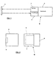
- the smoke detector shown in Fig. 1 works on the principle of extinction, that is Attenuation of a light beam by smoke entering it.
- the smoke detector is there as shown from a transmitter / receiver part referred to below as detector M. with a light transmitter 1, a light receiver arranged next to the light transmitter 1 2 and a microprocessor-controlled control and evaluation electronics 3, and from one Detector M opposite reflector 4.
- the detector M is adjusted in the factory so that the light beam emitted by the light transmitter is aligned horizontally and vertically.
- the light transmitter 1 sends a modulated infrared beam to the reflector 4, which hits the Beam reflected on the light receiver 2.
- the reflector 4 hits the Beam reflected on the light receiver 2.
- a part of the infrared beam is absorbed by these particles, and on the other hand, another part of the infrared beam is reflected by or on the particles scattered. Both effects weaken the incident on the light receiver 2 Light.
- Light transmitter 1 and light receiver 2 together with the electronics 3 form the so mentioned detector insert 6 (see Fig. 2).
- the reflector 4 is, for example, a retroreflective prism of the shape of a straight one Pyramid, the side surfaces of which are formed by isosceles, right-angled triangles. Such a reflector acts on the incident light as a polarizer and rotates its plane of vibration by approximately 90 °, this angle being able to vary within a certain range.
- the smoke detector shown is particularly for monitoring large storage and Manufacturing halls, rooms with complex ceiling constructions or art historically valuable Ceilings, covered courtyards, atrium buildings or reception halls, the distance between the transmitter / receiver part M and the reflector 4 between 5 and 100 m and in exceptional cases may even be more than 100 m.
- the detector M shown in FIG. 2 consists, in a known manner, of that in a base 5 attached detector insert 6 with the entire optics and electronics, of which a part can be located in the base 5, as well as from a cover 7, which covers the detector insert 6 serves.
- the lid is essentially a daylight filter; it is mounted over the and set detector insert 6 and fastened with screws.
- the base 5 is for example adjustable so that the inclination of the detector M and thus the axis of the light beam emitted by light transmitter 1 is adjustable. This kind of adjustment of the Detector M is referred to below as a rough adjustment.
- There are also in or on the detector M means for aligning the optics of light transmitter 1 and light receiver 2 are provided; a Alignment of the optics by means of these means is referred to below as fine adjustment.
- Detector cover 6 is removed for installation / commissioning of transmitter / receiver part M. and a tool for the mutual alignment of detector M and reflector 4 replaced.
- this tool is preferably an installation cover 8 light source formed by a laser 9 for emitting bundled light.
- the laser 9 is mounted on or in the installation cover 8 in such a way that it is connected to the light transmitter 1 (FIG. 1) of the detector M is aligned and thus "aims" in the same direction as the light transmitter 1.
- the laser 9 must not interfere with the light beam from the light transmitter 1.
- the power supply the laser 9 takes place either via detector base 5 via the network or via an im Installation cover 8 built-in battery.
- the light beam emitted by the laser 9 marks on the one opposite the detector M. Wall the point of impact of the light beam emitted by light transmitter 1 and thus the point on which the reflector 4 (Fig. 1) must be mounted.
- the installation cover 8 is removed from the detector M and through the detector cover 7 replaced, with which the linear smoke detector is ready for operation.
- Installation cover 8 is also helpful for application problems. If such problems (e.g. twisting of buildings, vibrations, undefined covers of the light beam, etc.) occur, the installation cover 8 is mounted and the laser point in critical Phases observed. This can confirm or rule out a possible application problem become.
Landscapes
- Chemical & Material Sciences (AREA)
- Analytical Chemistry (AREA)
- Business, Economics & Management (AREA)
- Emergency Management (AREA)
- Physics & Mathematics (AREA)
- General Physics & Mathematics (AREA)
- Fire-Detection Mechanisms (AREA)
- Investigating Or Analysing Materials By Optical Means (AREA)
Abstract
Description
- Fig. 1
- ein Blockschema eines linearen Rauchmelders; und
- Fig. 2
- eine schematische Darstellung des Sender-/Empfängerteils eines linearen Rauchmelders mit einem erfindungsgemässen Werkzeug.
- Der Melder M ist im Sockel 5 montiert und die Montage des Reflektors 4 ist noch nicht erfolgt. In diesem Fall markiert der Laserstrahl des Lasers 9 an der gegenüber liegenden Wand die Stelle, wo der Reflektor 4 montiert werden muss. Im Melder M ist anschliessend nur noch eine Feinjustierung notwendig.
- Die Montagestelle des Reflektors 4 ist definiert, beispielsweise ist der Reflektor 4 schon montiert, und der Melder M ist auf den Reflektor 4 auszurichten. Dann wird der Melder M mit dem aufgesetzten Installationsdeckel 8 so lange auf der Wand verschoben bis der Laserstrahl auf den Reflektor 4 oder dessen Montagestelle trifft, so dass die Montagestelle des Melders M markiert und anschliessend der Melder M montiert werden kann. Nach der Montage ist am Melder M nur noch eine Feinjustierung nötig. Voraussetzung für diese Art der Installation ist eine möglichst glatte Wand.
- Sowohl die Montagestelle des Reflektors 4 als auch diejenige des Melders M ist definiert, letztere dadurch, dass der Sockel 5 bereits montiert ist. Der Laserstrahl des Lasers 9 liefert einen Anhaltspunkt, wie gross die Abweichung zwischen Melder M und Reflektor 4 ist und erleichtert die Grobjustierung des Melders M. Es ist auch möglich, diese Abweichung auszumessen, aus einer Tabelle anhand der Abweichung und der Distanz zwischen Melder M und Reflektor 4 eine Verstellgrösse auszulesen und eine am Melder vorgesehene Verstelleinrichtung entsprechend zu verstellen. In beiden Fällen ist anschliessend nur noch eine Feinjustierung notwendig.
- Sowohl die Montagestelle des Reflektors 4 als auch diejenige des Melders M ist definiert; der Sockel 5 ist einstellbar. Der Laserpunkt wird mit dem einstellbaren Sockel 5 so positioniert, dass er den Reflektor 4 trifft. Am Melder M ist anschliessend nur noch eine Feinjustierung erforderlich.
Claims (10)
- Verfahren zur Installation oder Inbetriebnahme eines linearen Rauchmelders, welcher einen nachfolgend als Melder (M) bezeichneten Sender-/Empfängerteil mit einem Lichtsender (1) und einem Lichtempfänger (2) sowie einen dem Melder (M) gegenüber liegend angeordneten Reflektor (4) aufweist, wobei der Lichtsender (1) einen Lichtstrahl zum Reflektor (4) aussendet, der von diesem zum Lichtempfänger (2) reflektiert wird, dadurch gekennzeichnet, dass der Melder (M) am vorgesehenen Installationsort befestigt und anschliessend ein Installationswerkzeug mit einer in die gleiche Richtung wie der Lichtsender (1) zielenden Lichtquelle für die Aussendung von gebündeltem Licht auf den Melder (M) aufgesetzt und mit dem von der genannten Lichtquelle ausgesandten Licht der Installationsort des Reflektors (4) markiert wird.
- Verfahren zur Installation oder Inbetriebnahme eines linearen Rauchmelders, welcher einen nachfolgend als Melder (M) bezeichneten Sender-/Empfängerteil mit einem Lichtsender (1) und einem Lichtempfänger (2) sowie einen dem Melder (M) gegenüber liegend angeordneten Reflektor (4) aufweist, wobei der Lichtsender (1) einen Lichtstrahl zum Reflektor (4) aussendet, der von diesem zum Lichtempfänger (2) reflektiert wird, dadurch gekennzeichnet, dass der Reflektor (4) am vorgesehenen Installationsort montiert und anschliessend auf den Melder (M) ein Installationswerkzeug mit einer in die gleiche Richtung wie der Lichtsender (1) zielenden Lichtquelle für die Aussendung von gebündeltem Licht aufgesetzt wird, und dass der Melder (M) gegen den Reflektor (4) gerichtet und anhand der Lage des vom Installationswerkzeug an der gegenüber liegenden Wand erzeugten Lichtpunkts der Montageort des Melders (M) bestimmt wird.
- Verfahren nach Anspruch 1, dadurch gekennzeichnet, dass anschliessend an die Montage des Reflektors (4) eine Feinjustierung der Optik des Lichtsenders (1) und des Lichtempfängers (2) erfolgt.
- Verfahren nach Anspruch 2, dadurch gekennzeichnet, dass Melder (M) und Reflektor (4) am vorgesehenen Monategeort montiert werden und anschliessend das genannte Montagewerkzeug auf den Melder (M) aufgesetzt und der Melder (M) relativ zum Reflektor (4) ausgerichtet wird, wobei das Ausrichten des Melders (M) durch Veränderung von dessen Neigung erfolgt.
- Verfahren nach Anspruch 4, dadurch gekennzeichnet, dass das Ausrichten des Melders (M) anhand einer Verstellgrösse erfolgt, die durch die Grösse der Abweichung des Lichtpunkts vom Reflektor (4) und die Distanz zwischen Melder (M) und Reflektor (4) bestimmt ist.
- Werkzeug zur Durchführung des Verfahrens nach Anspruch 1 oder 2, gekennzeichnet durch einen auf die Vorderseite des Melders (M) aufsetzbaren Installationsdeckel (8) mit einem in diesen eingebauten Laser (9), dessen Lichtstrahl mit dem vom Lichtsender (1) ausgesandten im wesentlichen zusammenfällt.
- Werkzeug nach Anspruch 6, dadurch gekennzeichnet, dass der Melder (M) einen Sockel (5), einen in diesem befestigten und den Lichtsender (1) und den Lichtempfänger (2) enthaltenden Meldereinsatz (6) und einen den Meldereinsatz (6) abdeckenden Melderdeckel (7) aufweist, welcher für die Installation oder Inbetriebnahme des Melders (M) durch den Installationsdeckel (8) ersetzt wird.
- Werkzeug nach Anspruch 7, dadurch gekennzeichnet, dass der Laser (9) so in den Installationsdeckel (8) eingebaut ist, dass er mit dem Lichtsender (1) fluchtet.
- Werkzeug nach Anspruch 7 oder 8, dadurch gekennzeichnet, dass der Sockel (5) zur Verstellung der Neigung des Melders (M) ausgebildet ist.
- Werkzeug nach einem der Ansprüche 7 bis 9, dadurch gekennzeichnet, dass Mittel zum Ausrichten des Melders (M) anhand einer Verstellgrösse vorgesehen sind, welche durch die Grösse der Abweichung des Lichtpunkts des Lasers (9) vom Reflektor (4) und die Distanz zwischen Melder (M) und Reflektor (4) bestimmt ist.
Priority Applications (4)
| Application Number | Priority Date | Filing Date | Title |
|---|---|---|---|
| AT03001851T ATE303641T1 (de) | 2003-01-29 | 2003-01-29 | Verfahren und werkzeug zur installation eines linearen rauchmelders |
| EP03001851A EP1443479B1 (de) | 2003-01-29 | 2003-01-29 | Verfahren und Werkzeug zur Installation eines linearen Rauchmelders |
| DE50301082T DE50301082D1 (de) | 2003-01-29 | 2003-01-29 | Verfahren und Werkzeug zur Installation eines linearen Rauchmelders |
| US10/764,623 US20040155786A1 (en) | 2003-01-29 | 2004-01-26 | Method and tool for installing a linear smoke detector |
Applications Claiming Priority (1)
| Application Number | Priority Date | Filing Date | Title |
|---|---|---|---|
| EP03001851A EP1443479B1 (de) | 2003-01-29 | 2003-01-29 | Verfahren und Werkzeug zur Installation eines linearen Rauchmelders |
Publications (2)
| Publication Number | Publication Date |
|---|---|
| EP1443479A1 true EP1443479A1 (de) | 2004-08-04 |
| EP1443479B1 EP1443479B1 (de) | 2005-08-31 |
Family
ID=32605260
Family Applications (1)
| Application Number | Title | Priority Date | Filing Date |
|---|---|---|---|
| EP03001851A Expired - Lifetime EP1443479B1 (de) | 2003-01-29 | 2003-01-29 | Verfahren und Werkzeug zur Installation eines linearen Rauchmelders |
Country Status (4)
| Country | Link |
|---|---|
| US (1) | US20040155786A1 (de) |
| EP (1) | EP1443479B1 (de) |
| AT (1) | ATE303641T1 (de) |
| DE (1) | DE50301082D1 (de) |
Families Citing this family (9)
| Publication number | Priority date | Publication date | Assignee | Title |
|---|---|---|---|---|
| GB2426323A (en) * | 2005-05-16 | 2006-11-22 | Fire Fighting Entpr Ltd | Infra-red beam smoke detection system |
| FR2915284B1 (fr) * | 2007-04-20 | 2009-07-10 | Fabrication D Applic Et De Rea | Detecteur de fumee |
| US8704670B2 (en) * | 2010-11-22 | 2014-04-22 | Honeywell International Inc. | Target based smoke detection system |
| ES2451915R1 (es) | 2012-09-27 | 2014-06-02 | Utc Fire & Security Americas Corporation, Inc. | Sistema modular de detección de humo y procedimiento para montar un sistema de detección de humo |
| FR3027146B1 (fr) * | 2014-10-14 | 2016-12-09 | Soc D'etude Et De Fabrication Ind | Detecteur lineaire de fumee avec laser integre pour le positionnement du reflecteur |
| IT201800003638A1 (it) * | 2018-03-15 | 2019-09-15 | Tecnoalarm S R L | Rivelatore di fumo ad infrarossi e metodo per il suo allineamento |
| ES2966059T3 (es) * | 2020-03-30 | 2024-04-18 | Carrier Corp | Sistema de detector de humo de haz |
| CN117008231A (zh) * | 2022-04-28 | 2023-11-07 | 海湾安全技术有限公司 | 滤光器、烟雾探测器测试组件和测试方法 |
| CN115223321B (zh) * | 2022-07-19 | 2024-07-09 | 王蒙 | 消防监督检查便携工具 |
Citations (4)
| Publication number | Priority date | Publication date | Assignee | Title |
|---|---|---|---|---|
| US3614439A (en) * | 1969-12-08 | 1971-10-19 | Hughes Aircraft Co | Infrared aligning apparatus and method |
| US3782832A (en) * | 1973-04-12 | 1974-01-01 | Us Army | Method of boresight alignment of a weapon |
| DE3246805A1 (de) * | 1982-12-17 | 1984-06-20 | Krauss-Maffei AG, 8000 München | Justiervorrichtung fuer die feuerleitanlage eines kampffahrzeugs |
| EP1265205A1 (de) * | 2001-06-09 | 2002-12-11 | Siemens Building Technologies AG | Linearer Rauchmelder |
Family Cites Families (5)
| Publication number | Priority date | Publication date | Assignee | Title |
|---|---|---|---|---|
| DD151219A1 (de) * | 1980-06-30 | 1981-10-08 | Peter Hentschel | Anordnung zur geraden-und punktabsteckung |
| US4828377A (en) * | 1987-07-31 | 1989-05-09 | Putland Gavin R | Telescope aiming device |
| US4879814A (en) * | 1987-08-28 | 1989-11-14 | Texas Instruments Incorporated | Method and apparatus for boresight alignment of armored battlefield weapons |
| FR2751479B1 (fr) * | 1990-08-03 | 1998-11-06 | Thomson Csf | Procede et systeme de protection des equipements de veille ou de poursuite optroniques au regard d'une illumination |
| US5182863A (en) * | 1990-10-22 | 1993-02-02 | Spectra-Physics Laserplane, Inc. | Automatic plumb and level tool with acoustic measuring capability |
-
2003
- 2003-01-29 EP EP03001851A patent/EP1443479B1/de not_active Expired - Lifetime
- 2003-01-29 DE DE50301082T patent/DE50301082D1/de not_active Expired - Lifetime
- 2003-01-29 AT AT03001851T patent/ATE303641T1/de not_active IP Right Cessation
-
2004
- 2004-01-26 US US10/764,623 patent/US20040155786A1/en not_active Abandoned
Patent Citations (4)
| Publication number | Priority date | Publication date | Assignee | Title |
|---|---|---|---|---|
| US3614439A (en) * | 1969-12-08 | 1971-10-19 | Hughes Aircraft Co | Infrared aligning apparatus and method |
| US3782832A (en) * | 1973-04-12 | 1974-01-01 | Us Army | Method of boresight alignment of a weapon |
| DE3246805A1 (de) * | 1982-12-17 | 1984-06-20 | Krauss-Maffei AG, 8000 München | Justiervorrichtung fuer die feuerleitanlage eines kampffahrzeugs |
| EP1265205A1 (de) * | 2001-06-09 | 2002-12-11 | Siemens Building Technologies AG | Linearer Rauchmelder |
Also Published As
| Publication number | Publication date |
|---|---|
| ATE303641T1 (de) | 2005-09-15 |
| DE50301082D1 (de) | 2005-10-06 |
| US20040155786A1 (en) | 2004-08-12 |
| EP1443479B1 (de) | 2005-08-31 |
Similar Documents
| Publication | Publication Date | Title |
|---|---|---|
| EP0113468B1 (de) | Optisches Bauelement zum Umlenken optischer Strahlen | |
| DE3134815C2 (de) | Flächensicherung | |
| EP1394504B1 (de) | Lichtgitter | |
| DE102005019058A1 (de) | Vermessungssystem | |
| EP1443479B1 (de) | Verfahren und Werkzeug zur Installation eines linearen Rauchmelders | |
| DE4431889B4 (de) | Lichtstreuungstyp-Rauchsensor | |
| EP0251311B1 (de) | Sonnenschutzeinrichtung | |
| DE3231265C2 (de) | Strahlenteiler | |
| DE1548482A1 (de) | Entfernungsmess- oder aehnliche Vorrichtung mit selektiv fluoreszentem Sender | |
| EP0926646A1 (de) | Optischer Rauchmelder | |
| EP1884903A1 (de) | Justierung und Nachführung einer Lichtstrecke | |
| DE10231552A1 (de) | Laservisiervorrichtung | |
| EP0090322A1 (de) | Optische Fernsteuerungsvorrichtung für eine Wohnungstür | |
| DE19829659C1 (de) | Laser-Entfernungsmesser | |
| EP2722692B1 (de) | Sensor | |
| DE29511266U1 (de) | Markierungsgerät | |
| DE10140415A1 (de) | Verfahren zum Steuern der Helligkeit in einem mit Innenlicht und Außenlicht beleuchteten Raum | |
| DE2339575A1 (de) | Lichtschranken- und lichttastersystem zur herstellung verschiedenartiger lichtschranken- und lichttaster-bauformen unterschiedlicher optischer lichtstrahlenfuehrung | |
| WO2018219656A1 (de) | Bereitstellen einer drahtlosen kommunikationsverbindung zwischen wenigstens einem in einem vorgebbaren raumbereich positionierten kommunikationsendgerät und einem kommunikationsnetzwerk | |
| EP2634598B1 (de) | Optischer Sensor | |
| EP0810409A1 (de) | Anordnung für Lichtleitsystem | |
| EP2908297B1 (de) | Linearbrandmelder sowie Verfahren zum Betreiben des Linearbrandmelders | |
| DE102005033422B4 (de) | Einrichtung zur zweiseitigen optischen Kommunikation | |
| DE7512238U (de) | Laser-aggregat | |
| CH662223A5 (en) | Optoelectrical control module and use thereof |
Legal Events
| Date | Code | Title | Description |
|---|---|---|---|
| PUAI | Public reference made under article 153(3) epc to a published international application that has entered the european phase |
Free format text: ORIGINAL CODE: 0009012 |
|
| AK | Designated contracting states |
Kind code of ref document: A1 Designated state(s): AT BE BG CH CY CZ DE DK EE ES FI FR GB GR HU IE IT LI LU MC NL PT SE SI SK TR |
|
| AX | Request for extension of the european patent |
Extension state: AL LT LV MK RO |
|
| 17P | Request for examination filed |
Effective date: 20041220 |
|
| GRAP | Despatch of communication of intention to grant a patent |
Free format text: ORIGINAL CODE: EPIDOSNIGR1 |
|
| AKX | Designation fees paid |
Designated state(s): AT BE BG CH CY CZ DE DK EE ES FI FR GB GR HU IE IT LI LU MC NL PT SE SI SK TR |
|
| GRAS | Grant fee paid |
Free format text: ORIGINAL CODE: EPIDOSNIGR3 |
|
| GRAA | (expected) grant |
Free format text: ORIGINAL CODE: 0009210 |
|
| AK | Designated contracting states |
Kind code of ref document: B1 Designated state(s): AT BE BG CH CY CZ DE DK EE ES FI FR GB GR HU IE IT LI LU MC NL PT SE SI SK TR |
|
| PG25 | Lapsed in a contracting state [announced via postgrant information from national office to epo] |
Ref country code: IT Free format text: LAPSE BECAUSE OF FAILURE TO SUBMIT A TRANSLATION OF THE DESCRIPTION OR TO PAY THE FEE WITHIN THE PRESCRIBED TIME-LIMIT;WARNING: LAPSES OF ITALIAN PATENTS WITH EFFECTIVE DATE BEFORE 2007 MAY HAVE OCCURRED AT ANY TIME BEFORE 2007. THE CORRECT EFFECTIVE DATE MAY BE DIFFERENT FROM THE ONE RECORDED. Effective date: 20050831 Ref country code: CZ Free format text: LAPSE BECAUSE OF FAILURE TO SUBMIT A TRANSLATION OF THE DESCRIPTION OR TO PAY THE FEE WITHIN THE PRESCRIBED TIME-LIMIT Effective date: 20050831 Ref country code: IE Free format text: LAPSE BECAUSE OF FAILURE TO SUBMIT A TRANSLATION OF THE DESCRIPTION OR TO PAY THE FEE WITHIN THE PRESCRIBED TIME-LIMIT Effective date: 20050831 Ref country code: NL Free format text: LAPSE BECAUSE OF FAILURE TO SUBMIT A TRANSLATION OF THE DESCRIPTION OR TO PAY THE FEE WITHIN THE PRESCRIBED TIME-LIMIT Effective date: 20050831 Ref country code: SK Free format text: LAPSE BECAUSE OF FAILURE TO SUBMIT A TRANSLATION OF THE DESCRIPTION OR TO PAY THE FEE WITHIN THE PRESCRIBED TIME-LIMIT Effective date: 20050831 Ref country code: SI Free format text: LAPSE BECAUSE OF FAILURE TO SUBMIT A TRANSLATION OF THE DESCRIPTION OR TO PAY THE FEE WITHIN THE PRESCRIBED TIME-LIMIT Effective date: 20050831 Ref country code: FI Free format text: LAPSE BECAUSE OF FAILURE TO SUBMIT A TRANSLATION OF THE DESCRIPTION OR TO PAY THE FEE WITHIN THE PRESCRIBED TIME-LIMIT Effective date: 20050831 Ref country code: GB Free format text: LAPSE BECAUSE OF FAILURE TO SUBMIT A TRANSLATION OF THE DESCRIPTION OR TO PAY THE FEE WITHIN THE PRESCRIBED TIME-LIMIT Effective date: 20050831 |
|
| REG | Reference to a national code |
Ref country code: CH Ref legal event code: EP Ref country code: GB Ref legal event code: FG4D Free format text: NOT ENGLISH |
|
| REG | Reference to a national code |
Ref country code: IE Ref legal event code: FG4D Free format text: LANGUAGE OF EP DOCUMENT: GERMAN |
|
| REF | Corresponds to: |
Ref document number: 50301082 Country of ref document: DE Date of ref document: 20051006 Kind code of ref document: P |
|
| PG25 | Lapsed in a contracting state [announced via postgrant information from national office to epo] |
Ref country code: DK Free format text: LAPSE BECAUSE OF FAILURE TO SUBMIT A TRANSLATION OF THE DESCRIPTION OR TO PAY THE FEE WITHIN THE PRESCRIBED TIME-LIMIT Effective date: 20051130 Ref country code: BG Free format text: LAPSE BECAUSE OF FAILURE TO SUBMIT A TRANSLATION OF THE DESCRIPTION OR TO PAY THE FEE WITHIN THE PRESCRIBED TIME-LIMIT Effective date: 20051130 Ref country code: GR Free format text: LAPSE BECAUSE OF FAILURE TO SUBMIT A TRANSLATION OF THE DESCRIPTION OR TO PAY THE FEE WITHIN THE PRESCRIBED TIME-LIMIT Effective date: 20051130 Ref country code: SE Free format text: LAPSE BECAUSE OF FAILURE TO SUBMIT A TRANSLATION OF THE DESCRIPTION OR TO PAY THE FEE WITHIN THE PRESCRIBED TIME-LIMIT Effective date: 20051130 |
|
| PG25 | Lapsed in a contracting state [announced via postgrant information from national office to epo] |
Ref country code: ES Free format text: LAPSE BECAUSE OF FAILURE TO SUBMIT A TRANSLATION OF THE DESCRIPTION OR TO PAY THE FEE WITHIN THE PRESCRIBED TIME-LIMIT Effective date: 20051212 |
|
| PG25 | Lapsed in a contracting state [announced via postgrant information from national office to epo] |
Ref country code: AT Free format text: LAPSE BECAUSE OF NON-PAYMENT OF DUE FEES Effective date: 20060129 |
|
| PG25 | Lapsed in a contracting state [announced via postgrant information from national office to epo] |
Ref country code: BE Free format text: LAPSE BECAUSE OF NON-PAYMENT OF DUE FEES Effective date: 20060131 Ref country code: MC Free format text: LAPSE BECAUSE OF NON-PAYMENT OF DUE FEES Effective date: 20060131 Ref country code: LU Free format text: LAPSE BECAUSE OF NON-PAYMENT OF DUE FEES Effective date: 20060131 |
|
| PG25 | Lapsed in a contracting state [announced via postgrant information from national office to epo] |
Ref country code: PT Free format text: LAPSE BECAUSE OF FAILURE TO SUBMIT A TRANSLATION OF THE DESCRIPTION OR TO PAY THE FEE WITHIN THE PRESCRIBED TIME-LIMIT Effective date: 20060222 |
|
| NLV1 | Nl: lapsed or annulled due to failure to fulfill the requirements of art. 29p and 29m of the patents act | ||
| PG25 | Lapsed in a contracting state [announced via postgrant information from national office to epo] |
Ref country code: HU Free format text: LAPSE BECAUSE OF FAILURE TO SUBMIT A TRANSLATION OF THE DESCRIPTION OR TO PAY THE FEE WITHIN THE PRESCRIBED TIME-LIMIT Effective date: 20060301 |
|
| REG | Reference to a national code |
Ref country code: IE Ref legal event code: FD4D |
|
| GBV | Gb: ep patent (uk) treated as always having been void in accordance with gb section 77(7)/1977 [no translation filed] |
Effective date: 20050831 |
|
| PLBE | No opposition filed within time limit |
Free format text: ORIGINAL CODE: 0009261 |
|
| STAA | Information on the status of an ep patent application or granted ep patent |
Free format text: STATUS: NO OPPOSITION FILED WITHIN TIME LIMIT |
|
| 26N | No opposition filed |
Effective date: 20060601 |
|
| EN | Fr: translation not filed | ||
| PG25 | Lapsed in a contracting state [announced via postgrant information from national office to epo] |
Ref country code: FR Free format text: LAPSE BECAUSE OF FAILURE TO SUBMIT A TRANSLATION OF THE DESCRIPTION OR TO PAY THE FEE WITHIN THE PRESCRIBED TIME-LIMIT Effective date: 20061027 |
|
| REG | Reference to a national code |
Ref country code: CH Ref legal event code: PFA Owner name: SIEMENS BUILDING TECHNOLOGIES AG C-IPR Free format text: SIEMENS BUILDING TECHNOLOGIES AG#BELLERIVESTRASSE 36#8034 ZUERICH (CH) -TRANSFER TO- SIEMENS BUILDING TECHNOLOGIES AG C-IPR#GUBELSTRASSE 22#6300 ZUG (CH) |
|
| BERE | Be: lapsed |
Owner name: SIEMENS BUILDING TECHNOLOGIES A.G. Effective date: 20060131 |
|
| PG25 | Lapsed in a contracting state [announced via postgrant information from national office to epo] |
Ref country code: EE Free format text: LAPSE BECAUSE OF FAILURE TO SUBMIT A TRANSLATION OF THE DESCRIPTION OR TO PAY THE FEE WITHIN THE PRESCRIBED TIME-LIMIT Effective date: 20050831 |
|
| PG25 | Lapsed in a contracting state [announced via postgrant information from national office to epo] |
Ref country code: TR Free format text: LAPSE BECAUSE OF FAILURE TO SUBMIT A TRANSLATION OF THE DESCRIPTION OR TO PAY THE FEE WITHIN THE PRESCRIBED TIME-LIMIT Effective date: 20050831 |
|
| PG25 | Lapsed in a contracting state [announced via postgrant information from national office to epo] |
Ref country code: FR Free format text: LAPSE BECAUSE OF FAILURE TO SUBMIT A TRANSLATION OF THE DESCRIPTION OR TO PAY THE FEE WITHIN THE PRESCRIBED TIME-LIMIT Effective date: 20050831 Ref country code: CY Free format text: LAPSE BECAUSE OF FAILURE TO SUBMIT A TRANSLATION OF THE DESCRIPTION OR TO PAY THE FEE WITHIN THE PRESCRIBED TIME-LIMIT Effective date: 20050831 |
|
| REG | Reference to a national code |
Ref country code: CH Ref legal event code: PUE Owner name: SIEMENS AKTIENGESELLSCHAFT Free format text: SIEMENS BUILDING TECHNOLOGIES AG C-IPR#GUBELSTRASSE 22#6300 ZUG (CH) -TRANSFER TO- SIEMENS AKTIENGESELLSCHAFT#WITTELSBACHERPLATZ 2#80333 MUENCHEN (DE) Ref country code: CH Ref legal event code: NV Representative=s name: SIEMENS SCHWEIZ AG |
|
| REG | Reference to a national code |
Ref country code: CH Ref legal event code: PUE Owner name: SIEMENS SCHWEIZ AG, CH Free format text: FORMER OWNER: SIEMENS AKTIENGESELLSCHAFT, DE |
|
| REG | Reference to a national code |
Ref country code: DE Ref legal event code: R081 Ref document number: 50301082 Country of ref document: DE Owner name: SIEMENS SCHWEIZ AG, CH Free format text: FORMER OWNER: SIEMENS AKTIENGESELLSCHAFT, 80333 MUENCHEN, DE Effective date: 20150407 |
|
| PGFP | Annual fee paid to national office [announced via postgrant information from national office to epo] |
Ref country code: DE Payment date: 20190319 Year of fee payment: 17 |
|
| PGFP | Annual fee paid to national office [announced via postgrant information from national office to epo] |
Ref country code: CH Payment date: 20190402 Year of fee payment: 17 |
|
| REG | Reference to a national code |
Ref country code: DE Ref legal event code: R119 Ref document number: 50301082 Country of ref document: DE |
|
| REG | Reference to a national code |
Ref country code: CH Ref legal event code: PL |
|
| PG25 | Lapsed in a contracting state [announced via postgrant information from national office to epo] |
Ref country code: DE Free format text: LAPSE BECAUSE OF NON-PAYMENT OF DUE FEES Effective date: 20200801 |
|
| PG25 | Lapsed in a contracting state [announced via postgrant information from national office to epo] |
Ref country code: CH Free format text: LAPSE BECAUSE OF NON-PAYMENT OF DUE FEES Effective date: 20200131 Ref country code: LI Free format text: LAPSE BECAUSE OF NON-PAYMENT OF DUE FEES Effective date: 20200131 |