EP1443509A2 - Verfahren zur Signalauswertung, Vorrichtung zur Informationsaufzeichung/-wiedergabe, Informationswiedergabevorrichtung und Informationsaufzeichnungsmedium - Google Patents
Verfahren zur Signalauswertung, Vorrichtung zur Informationsaufzeichung/-wiedergabe, Informationswiedergabevorrichtung und Informationsaufzeichnungsmedium Download PDFInfo
- Publication number
- EP1443509A2 EP1443509A2 EP04000723A EP04000723A EP1443509A2 EP 1443509 A2 EP1443509 A2 EP 1443509A2 EP 04000723 A EP04000723 A EP 04000723A EP 04000723 A EP04000723 A EP 04000723A EP 1443509 A2 EP1443509 A2 EP 1443509A2
- Authority
- EP
- European Patent Office
- Prior art keywords
- evaluation value
- evaluation
- group
- signal
- equalization
- Prior art date
- Legal status (The legal status is an assumption and is not a legal conclusion. Google has not performed a legal analysis and makes no representation as to the accuracy of the status listed.)
- Ceased
Links
Images



Classifications
-
- G—PHYSICS
- G11—INFORMATION STORAGE
- G11B—INFORMATION STORAGE BASED ON RELATIVE MOVEMENT BETWEEN RECORD CARRIER AND TRANSDUCER
- G11B20/00—Signal processing not specific to the method of recording or reproducing; Circuits therefor
- G11B20/10—Digital recording or reproducing
- G11B20/10009—Improvement or modification of read or write signals
- G11B20/10046—Improvement or modification of read or write signals filtering or equalising, e.g. setting the tap weights of an FIR filter
- G11B20/10055—Improvement or modification of read or write signals filtering or equalising, e.g. setting the tap weights of an FIR filter using partial response filtering when writing the signal to the medium or reading it therefrom
- G11B20/10101—PR2 or PR(1,2,1), i.e. partial response class 2, polynomial (1+D)2=1+2D+D2
-
- G—PHYSICS
- G11—INFORMATION STORAGE
- G11B—INFORMATION STORAGE BASED ON RELATIVE MOVEMENT BETWEEN RECORD CARRIER AND TRANSDUCER
- G11B20/00—Signal processing not specific to the method of recording or reproducing; Circuits therefor
- G11B20/10—Digital recording or reproducing
- G11B20/10009—Improvement or modification of read or write signals
-
- G—PHYSICS
- G11—INFORMATION STORAGE
- G11B—INFORMATION STORAGE BASED ON RELATIVE MOVEMENT BETWEEN RECORD CARRIER AND TRANSDUCER
- G11B20/00—Signal processing not specific to the method of recording or reproducing; Circuits therefor
- G11B20/10—Digital recording or reproducing
- G11B20/10009—Improvement or modification of read or write signals
- G11B20/10046—Improvement or modification of read or write signals filtering or equalising, e.g. setting the tap weights of an FIR filter
- G11B20/10055—Improvement or modification of read or write signals filtering or equalising, e.g. setting the tap weights of an FIR filter using partial response filtering when writing the signal to the medium or reading it therefrom
-
- G—PHYSICS
- G11—INFORMATION STORAGE
- G11B—INFORMATION STORAGE BASED ON RELATIVE MOVEMENT BETWEEN RECORD CARRIER AND TRANSDUCER
- G11B20/00—Signal processing not specific to the method of recording or reproducing; Circuits therefor
- G11B20/10—Digital recording or reproducing
- G11B20/10009—Improvement or modification of read or write signals
- G11B20/10046—Improvement or modification of read or write signals filtering or equalising, e.g. setting the tap weights of an FIR filter
- G11B20/10055—Improvement or modification of read or write signals filtering or equalising, e.g. setting the tap weights of an FIR filter using partial response filtering when writing the signal to the medium or reading it therefrom
- G11B20/10111—Improvement or modification of read or write signals filtering or equalising, e.g. setting the tap weights of an FIR filter using partial response filtering when writing the signal to the medium or reading it therefrom partial response PR(1,2,2,1)
-
- G—PHYSICS
- G11—INFORMATION STORAGE
- G11B—INFORMATION STORAGE BASED ON RELATIVE MOVEMENT BETWEEN RECORD CARRIER AND TRANSDUCER
- G11B20/00—Signal processing not specific to the method of recording or reproducing; Circuits therefor
- G11B20/10—Digital recording or reproducing
- G11B20/18—Error detection or correction; Testing, e.g. of drop-outs
- G11B20/1816—Testing
-
- G—PHYSICS
- G11—INFORMATION STORAGE
- G11B—INFORMATION STORAGE BASED ON RELATIVE MOVEMENT BETWEEN RECORD CARRIER AND TRANSDUCER
- G11B7/00—Recording or reproducing by optical means, e.g. recording using a thermal beam of optical radiation by modifying optical properties or the physical structure, reproducing using an optical beam at lower power by sensing optical properties; Record carriers therefor
- G11B7/004—Recording, reproducing or erasing methods; Read, write or erase circuits therefor
- G11B7/006—Overwriting
- G11B7/0062—Overwriting strategies, e.g. recording pulse sequences with erasing level used for phase-change media
Definitions
- the present invention relates to a signal evaluation method for evaluating a signal reproduced from an information recording medium, an information recording/reproducing apparatus, and an information recording medium. More specifically, the present invention is directed to improvements in evaluation means and an evaluation method which reproduce a signal from the information recording medium and evaluates the reproduced signal.
- PRML partial response and maximum likelihood
- Jpn. Pat. Appln. KOKAI Publication No. 2002-358738 discloses a technique for evaluating the signal quality in a system using the PRML discrimination method.
- a differential metric distribution is prepared. Based on the assumption that the differential metric distribution is a normal distribution, a standard deviation ⁇ and a mean value ⁇ are obtained. Of the portions of the normal distribution, the portion whose peak is not more than 0 is detected, and an area (error rate) of the detected portion is calculated from the standard deviation ⁇ and the mean value ⁇ , using an error function.
- the normal distribution is not necessarily accurate. In practice, a plurality of different normal distributions are superposed. This being so, the error rate cannot be accurately estimated, and the signal quality cannot be evaluated.
- an object of the present invention is to provide a method capable of accurately evaluating the signal quality. It is also an object of the present invention to provide an information recording/reproducing apparatus capable of performing signal recording and reproduction with high reliability. It is further an object of the present invention to provide an information recording medium for which information recording and reproduction can be performed with high reliability.
- the present invention relates to a method which is adapted for an information recording/reproducing apparatus using the PRML discrimination method, and which comprises the steps of: detecting matching between identification data and a plurality of predetermined bit sequence pairs; calculating a bit sequence and corresponding two ideal responses when the matching is detected; obtaining Euclidean distances between the two ideal responses and equalization signals; obtaining a difference between the Euclidean distances; obtaining a mean value and a standard deviation with respect to the difference between the Euclidean distances; and calculating a quality evaluation value of a reproduction signal based on the mean value, the standard deviation, an appearance probability of the predetermined bit sequence, and a Hamming distance between the predetermined bit sequence pairs.
- the present invention is not limited to this, and covers the method, apparatus and medium to be described below.
- the PRML discrimination method utilizes PR (partial response) characteristics, which correspond to the recording/reproducing characteristics.
- PR (1,2,2,1) characteristic refers to the case where the response to sign bit "1" is "1221". Convolution between a sign bit sequence and sequence "1221" is a response. For example, the response to sign bit sequence "0010000” is “0012210.” Likewise, the response to sign bit sequence "00110000” is “00134310", the response to sign bit sequence "001110000" is "000135531”, and the response to "00011110000” is "00013565310.”
- Euclidean distances are used as distances for comparison.
- the ideal responses that enable the Euclidian distances of equalization signals S 1 and S 2 to become shortest are [6 6 6 5 3 1 0 0 0] (i.e., ideal responses of bit sequence [1 1 1 1 1 1 1 0 0 0 0 0 0].
- the ideal responses that enable the Euclidian distances of equalization signals S 1 and S 2 to become second shortest are [6 6 5 3 1 0 0 0 0] (i.e., outputs of bit sequence [1 1 1 1 1 0 0 0 0 0 0 0 0].
- E min 2 and E next 2 are calculated in relation to S 1 as below.
- E min 2 and E next 2 are calculated in relation to S 2 as below.
- E min 2 - E next 2 is 8.8 with respect to S 1 , and is 7.4 with respect to S 2 . This means that the occurrence of errors is less likely in the case of S 1 .
- a distribution close to "0" is regarded as a normal distribution, and the standard deviation ⁇ and the mean value ⁇ of that normal distribution are obtained.
- the portion whose peak is not more than 0 is detected, and an area (error rate) of the detected portion is calculated from the standard deviation ⁇ and the mean value ⁇ , using an error function.
- the SAM distribution is a superposition of a plurality of normal distributions of different standard deviations and mean values, and the values lower than threshold value Th do not form a normal distribution. This being so, the error rate cannot be accurately estimated, and the signal quality cannot be evaluated.
- the present invention is intended to provide a method that enables more reliable evaluation.
- the PR characteristic is PR(1,2,2,2,1) characteristic and the modulation code is (1,7)RLL code.
- E PF,S denotes an Euclidian distance between ideal signal PF and reproduction signal S
- E PT,S denotes an Euclidian distance between ideal signal PT and reproduction signal S
- E P1,P2 denotes an Euclidian distance between signals P1 and P2.
- a Euclidian distance expressed by formula (2) is advantageously used when patterns T and F are selected.
- an error occurrence probability decreases exponentially in response to an increase in the Euclidian distance E T,F between patterns T and F. Therefore, an estimated value of bER can be obtained by detecting a pair of patterns between which the Euclidian distance E T,F is shorter than a predetermined value.
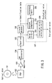
- FIG. 3 is a block diagram illustrating the configuration of one embodiment of the present invention.
- information which is recorded on an information recording medium (an optical disk) 101 as marks and spaces, is read out by an optical head device (PUH) 102 as feeble analog signals.
- An amplifier 103 amplifies the feeble analog signals to have sufficiently high levels.
- An analog-digital (AD)converter 104 converts the amplified analog signals into digital reproduction signals.
- An equalizer 105 equalizes the digital reproduction signals so that the digital reproduction signals have waveforms corresponding to a PR characteristic to be used (the digital reproduction signals having such waveforms will be hereinafter referred to simply as "equalization signals").
- the equalization signals are supplied to a Viterbi decoder 106 and an evaluation value calculator 107.
- the Viterbi decoder 106 decodes the equalization signals in accordance with the Viterbi algorithm, thereby obtaining binary identification data.
- the identification data is supplied to a circuit (not shown), and is delivered to the user after it is subject to decoding, error correction or another kind of processing desired.
- the identification data is supplied also to the evaluation value calculator 107 as well. Using the equalization signals and the identification data, the evaluation value calculator 107 calculates evaluation values.
- the evaluation value calculator 107 comprises a delay circuit 201 which is used for timing, and a pattern comparator 203 which executes pattern comparison between the identification data and the data in a reference table.
- the evaluation value calculator 107 also comprises an evaluation value calculation unit 204 which executes evaluation value calculation by using equalization signals and ideal signals obtained by the pattern comparison.
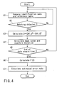
- FIG. 4 illustrates how evaluation value calculation takes place.
- Identification data is acquired by the Viterbi decoder 106, and this identification data is compared with predetermined data patterns (reference data) stored in a reference table 202 (Step A1).
- the reference table 202 stores pattern pairs T and F which are likely to mix up. Pattern T is likely to be mistaken for pattern F; conversely, pattern F is likely to be mistaken for pattern T.
- the comparison described above shows that the identification data matches data pattern T stored in the reference table 202, the values of D expressed by formula (1) are calculated, using equalization signals S, the ideal signal PT of pattern T, and ideal signal PF of pattern F.
- a mean value and a standard deviation are calculated with respect to a plurality of D values.
- the value of F(0) expressed by formula (3) is calculated.
- the estimated error rate expressed by formula (4) is calculated. If the number of pieces of data is insufficient, it is not possible to accurately calculate the estimated error rate.
- the number of pieces of data should be 100,000 or more.
- Table (1-1), tables (1-2) through (2-1) and table (2-2) are set forth at the end of the body of the specification.
- examples of groups of pattern pairs T and F that are likely to mix up are indicated.
- pattern pairs T and F that are likely to mix up are classified into groups: the group shown in tables (1-1) and (1-2); and the group shown in tables (2-1) and (2-2).
- 108 pairs are shown, and the pairs in one group differ from those of the other in terms of the way in which they are classified.
- each of the 108 pattern pairs are equivalent to each other as far as their first four bits or the last four bits are concerned, but their intermediate bits differ from each other (T ⁇ F). In addition, they satisfy the modulation rule of the (1,7)RLL code.
- each of the 108 pairs is regarded as a group, so that the total number of groups is 108. Since the patterns are classified in detail, the estimated error rate can be as accurate as possible. However, since the number of pieces of data that must be processed is large, the processing circuit is inevitably complex.
- Tables (2-1) and (2-2) are intended to reduce the number of pieces of data processed, thereby enabling the use of a simple processing circuit, and also to fully satisfy the accuracy required of the estimated error rate.
- patterns are classified into groups, paying special attention to how many times the same code bit ("1" or "0") appears consecutively. In the following description, it is assumed that code bit "1" corresponds to a mark and code bit "0" corresponds to a space.
- nTm A sequence in which code bit "1" appears consecutively n times (i.e., n straight code bits of "1")
- mTs a sequence in which code bit "0" appears consecutively n times (i.e., n straight code bits of "0")
- nTm a sequence in which code bit "0" appears consecutively n times
- mTs a sequence in which code bit "0" appears consecutively n times
- the total number of groups is 16. Since an increased number of patterns are processed as one group, the number of pieces of data required decreased, accordingly, and a simple processing circuit suffices.
- groups 1-3 utilize 3Tm, 4Tm and nTm (n > 4), respectively, but 3Tm, 4Tm, 5Tm, nTm (n > 5) may be used instead. In this case, the number of pattern pairs is increased, accordingly.
- the estimated value (estimated bER) calculated according to the method of embodiment 1 exceeds 1 ⁇ 10 -3 , this means that there are a large number of discrimination errors that cannot be corrected even by subsequently-executed error correction processing. Therefore, information recording mediums are selected in such a way that the estimated bER becomes not more than 1 ⁇ 10 -3 .
- the estimated bER value must be not more than 1 ⁇ 10 -5 in consideration of various factors that deteriorate the performance of a recording/reproducing system, such as focusing errors and optical aberration. This being so, information recording mediums whose estimated bER values are not more than 1 ⁇ 10 -5 are selected.
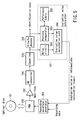
- FIG. 5 illustrates a waveform adjusting circuit that uses the estimated value described above or an intermediate calculation result used for calculating the estimated value.
- the same reference numerals as used in FIG. 3 represent similar or corresponding structural elements.
- a recording waveform generator 301 makes recording parameter adjustment in such a manner that the evaluation value or the intermediate calculation result satisfies a predetermined value. Recording data subjected to the adjustment is supplied to an optical head device 102.
- a recording waveform generator adjusts the recording parameter to lengthen the rear end of the mark when the consecutive patterns 3Tm and 3Ts are recorded.
- the recording parameters are adjusted likewise, thereby lowering the probability of recognition errors.
- the direction in which the recording parameters should be adjusted (that is, whether a mark should be lengthened or shortened) is obvious from the attributes of a group.
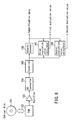
- FIGS. 6 and 7 show the third and fourth embodiments of the present invention.
- the embodiment shown in FIG. 6 will be described prior to that shown in FIG. 7.
- information which is recorded on an information recording medium (an optical disk) 101 as marks and spaces, is read out by an optical head device (PUH) 102 as feeble analog signals.
- An amplifier 103 amplifies the feeble analog signals to have sufficiently high levels.
- An analog-digital (AD)converter 104 converts the amplified analog signals into digital reproduction signals.
- An equalizer 105 equalizes the digital reproduction signals so that the digital reproduction signals have waveforms corresponding to a PR characteristic to be used. Then, the equalization signals are supplied to a Viterbi decoder 106, a first evaluation value calculator 107 and a second evaluation value calculator 108.
- the Viterbi decoder 106 decodes the equalization signals in accordance with the Viterbi algorithm, thereby obtaining binary identification data.
- the identification data is supplied to a circuit (not shown), and is delivered to the user after it is subject to decoding, error correction or another kind of processing desired.
- the identification data is supplied also to the first and second evaluation value calculators 107 and 108 as well.
- the first evaluation calculator 107 has a configuration equivalent to that shown in FIG. 3, and outputs a first evaluation value similar to the evaluation value shown in FIG. 3.
- the second evaluation value calculator 108 calculates a second evaluation value based on the equalization signals and the identification data.
- the second evaluation value calculator 108 is used in a method for evaluating the quality of signals which are recorded on an optical disk medium beforehand by forming embossed portions, or which are recorded by use of an optical information recording apparatus.
- the second evaluation value calculator 108 calculates a target signal and an equalization error for each clock period.
- the target signal is obtained from a predetermined data sequence and a predetermined partial response characteristic, and the equalization error represents the difference between reproduced signals output in a clock period. Based on the autocorrelation, the second evaluation value calculator 108 evaluates the signal quality.
- the Viterbi decoding In the PRML method, data determination is made on the basis of an algorithm generally referred to as the Viterbi decoding.
- the Viterbi decoding the square of the difference between the value of a reproduced signal and the predetermined level determined by a partial response is calculated in each clock period, and the sum of the squares is calculated with respect to each path. The data is decoded by selecting the path for which the calculated sum of the squares is smallest.
- Binary data can be expressed in two ways: one is to use a combination of "1" and “0”, and the other is to use a combination of "1” and “-1". The latter way is used in the specification of the present application.
- the amplitude of a waveform is half that of the case where combination of "1" and “-1” is used.
- the square of an Euclidian distance is one fourth of the square d 2 of the Euclidian distance described above. In short, the value of S described later should be reduced to one fourth.
- the restriction expressed as ⁇ i ⁇ i+1 ⁇ -1 should only be imposed on the combinations of ⁇ i .
- d 1, such patterns as exemplified by (1, -1, 1) and (-1, 1, -1) are not allowed.
- Which value, ⁇ (y k - ⁇ b k-i h i ) 2 or ⁇ ( y k - ⁇ c k-i h i ) 2 , is larger can be determined by assuming that a polynomial coefficient defined by the difference between B(D)H(D) and C(D)H(d) is a vector component, defining an error vector based on the assumption, and projecting the equalization error on the error vector.
- the probability of occurrence of a detection error is defined as the probability of the noise value (the noise dispersion) becoming larger than half of the Euclidian distance between paths.
- the probability of data sequence bk being mistaken as data sequence ck is higher than the probability of the value of the equalization error projected on 2*(1,2,2,1) becoming larger than half of the Euclidian distance between two paths (the Euclidian distance in this case is 2*(1+2*2+2*2+1) 1/2 ).
- the dispersion CN of the noise projected on the error vector is expressed as follows:
- Half of the Euclidian distance between two paths i.e., a value corresponding to the signal amplitude
- E/CN is obtained as an index correlated with the probability of an error.
- a time delay operator expressed based on the clock time is determined as D
- bk and ck were referred to as data sequences that were likely to mix up. It should be noted, however, that only bk need not be selected for the calculation of an equalization error when the dispersion of the noise projected on an error vector is calculated.
- the dispersion of equalization errors need not be calculated by extracting the points of time corresponding to data sequence bk from data sequence ak used for generating a target signal. That is, the dispersion may be calculated using the equalization error calculated in each clock time. As long as the distribution of equalization errors conforms to a Gaussian distribution and is therefore probabilistic, the same dispersion is calculated without reference to the distribution data used for calculation.
- the same dispersion is calculated.
- the calculation of noise dispersion may be based on a specific data sequence bk, but it is advantageous to calculate the dispersion of equalization errors without selecting any particular pattern because this way for calculation does not require a complicated circuit configuration.
- FIG. 8 is a block diagram illustrating one example of the second evaluation value calculator used for calculating the signal quality evaluation value S.
- a reproduction waveform is supplied to an AD converter, by which it is sampled based on a predetermined frequency. After this sampling, the reproduction waveform is supplied to an equalizer including a PLL (phase-locked loop) circuit.
- the equalizer outputs equalization reproduction waveform data in each clock period. The equalization is performed in such a manner as to suppress the noise components and permit the reproduction waveform to be as analogous as possible to a target waveform based on a PR waveform.
- a signal quality evaluator 108 calculates signal quality evaluation value S on the basis of the equalization reproduction waveform it receives, and evaluates the quality of the reproduction waveform.
- a target signal generator 21 Assuming that a reference PR waveform is hi and binary data obtained by a discriminator (which is typically a Viterbi decoder) is ak, a target signal generator 21 generates a target signal Rk on the basis of formula (10) set forth below.
- a comparison operation unit 22 outputs equalization error vk, which is the difference between equalization reproduction signal y k corresponding to each clock period and Rk.
- taps 23 delay the equalization errors by the length of time corresponding to each clock period. The equalization errors are added together after processing them based on tap coefficient ⁇ i .
- ⁇ i is a coefficient of N(D) described above.
- Combinations of ⁇ i are discriminated using j, and the value of S corresponding to them is defined as Sj.
- the total number m of taps (D) varies depending upon j.
- the equalization errors added together based on the tap coefficients, and the square of the sum of the equalization errors is calculated by a multiplier 24.
- An adder 25 adds squares until the total number of equalization error samples becomes N.
- a value obtained as a result of this addition changes in proportion to the dispersion of noise projected on an error vector. (If the value is divided by N and ⁇ i 2 , the quotient represents a dispersion. However, since N and ⁇ i 2 are constants, they are used as a coefficient of the multiplier 24.)
- a divider 26 outputs the reciprocal number of the value described above, and a multiplier 27 outputs mathematical product (N ⁇ i 2 )* ⁇ i 2 , thereby calculating the value of S.
- the total number of reproduction waveform samples should accurately be N+m. However, since m is 20 at most, as against more than 10 4 of N, the total number of samples required (which will be referred to later) is described as N throughout the specification.
- Another embodiment is directed to a method of evaluating the quality of signals recorded on an optical disk.
- Ri is the autocorrelation of an equalization error.
- the equalization error is white.
- the reproduction method using PR(12221) equalization performs a predetermined product-sum operation with respect to the autocorrelation of equalization error V m obtained at each clock time so, thereby obtaining the values S1, S2 and S3 given in the formulas (1-1), (1-2) and (1-3) below.
- the quality of a reproduced signal can be evaluated by detecting the smallest value of S1, S2 and S3.
- FIG. 9 is a block diagram illustrating another example of the second evaluation value calculator used for calculating the signal quality evaluation value S.
- the second evaluation value calculator of FIG. 9 differs from that shown in FIG. 8 in that autocorrelations of equalization errors are calculated, are weighted in a predetermined manner (i.e., they are multiplied based on coefficient ⁇ i by means of multipliers 61), and are then added together.
- the number of multipliers 61 (FIG. 9) required is dependent on Sj to be calculated, and nine multipliers are required for calculating S3. If it is onerous to change the number of multipliers in accordance with patterns, a sufficiently large number of multipliers (e.g., 15 to 20 multipliers) are prepared, and the multipliers coefficients that are not required for calculation are set at "0".
- the configuration shown in FIG. 9 may be modified in such a way as not to calculate mean values (division by sample total number N is not performed). In such a case, what is required is to calculate a sum and multiply the numerator of S (the numerator is either 12 or 14 in this embodiment) with N.
- the signal quality is evaluated on the basis of equalization errors corresponding to clock times, without making determination with respect to the data sequences that are likely to mix up.
- the present invention is not limited to this configuration.
- those data sequences that are likely to mix up may be selected, and equalization errors corresponding to such data sequences may be used for evaluating the signal quality of the signals of an optical disk.
- the signal quality evaluation device shown in FIG. 8 or 9 is provided with a determination device 71, such as that shown in FIG. 10.
- equalization errors are collected with respect to only the data patterns that are likely to mix up, and subjected to evaluation.
- the determination device 71 shown in FIG. 10 has a function of outputting evaluation errors to processing blocks with respect to predetermined patterns only.
- the system described above enables evaluation of the quality of signals even if those signals are recorded on an information recording medium in such a high density mode as does not permit signal quality evaluation based on jitter.
- the system enables determination of optimal recording and reproduction conditions, using the evaluated signal quality as an index.
- a recognition error is likely to occur at a transitional point of time when the code bit changes from “0" to "1” or from "1" to "0".
- the bit error rate can be estimated based only on bit sequences which may give rise to a recognition error.
- the PRML method is a discrimination method that assumes the linearity of reproduction signals. If the quality of the signals other than the bit sequences that are likely to give rise to a recognition error is poor, the PRML discrimination circuit may not operate properly. Therefore, all signals must provide linearity when their quality is evaluated.
- the signal quality evaluation method of the first evaluation value calculator of the present invention estimates a bit error rate.
- the signal quality evaluation method of the second evaluation value calculator evaluates the linearity of equalization signals. Since both the bit error rate and the linearity, it is possible to select mediums that satisfy the desired values of both the bit error rate and the linearity.
- the evaluation of the bit error rate and the evaluation of the linearity are performed independently of each other. By examining the relationships between the bit error rate and the linearity, the reason for poor signal quality can be easily identified. This enables easy parameter adjustment of recording waveforms, which adjustment is made within a recording waveform generator (not shown).
- the second evaluation value of the third embodiment is less than 12, this means that there will be a large number of discrimination errors even if error correction processing (not shown) is executed later. Therefore, the second evaluation value should be equal to 12 or more to avoid such errors when information recording mediums are selected.
- the second evaluation value should be at least 15. Therefore, the second evaluation value should be equal to 15 or more to avoid such adverse factors when information recording mediums are selected.
- An information recording medium that does not satisfy both the first and second evaluation values has problems in that there may be a large number of discrimination errors even if error correction processing (not shown) is executed later.
- the first evaluation value should be not more than 1 ⁇ 10 -3 and the second evaluation value should be not less than 12.
- the first evaluation value should be not more than 5 ⁇ 10 -5 and the second evaluation value should be not less than 15.
- the first and second evaluation values are determined in these ranges when information recording mediums are selected.
- FIG. 7 shows the fourth embodiment of the present invention.
- an error correction encoder 121 encodes binary user data.
- a product code is used as an error correction code.
- the user data is arranged in two dimensions, and the parities of the user data are calculated with respect to the row and column directions.
- the calculated parities (redundancy bits) are added.
- the redundancy bits added to the user data in the row direction will be referred to as PI (inner parity), and the redundancy bits added to the user data in the column direction will be referred to as PO (outer parity).
- a modulator 122 performs modification processing in accordance with the (1,7)RLL code.
- a recording waveform generator 123 generates a recording waveform in accordance with the modified data, and an optical head device 102 records information on an optical disk 101 as marks and spaces.
- a preamplifier 103, an analog-digital (AD)converter 104, an equalizer 105, a Viterbi decoder 106, a first evaluation value calculator 107 and a second evaluation value calculator 108 are similar in configuration to those shown in FIG. 6.
- the Viterbi decoder 106 decodes equalization signals in accordance with the Viterbi algorithm, thereby obtaining binary identification data.
- the identification data is supplied to a demodulator 111, by which it is subject to the decoding process based on the Viterbi algorithm. Subsequently, the identification data is supplied to an error correction decoder 112, for error correction, and is then supplied to a succeeding circuit.
- the identification data is supplied also to first and second evaluation value calculators 107 and 108 as well.
- the first evaluation calculator 107 has a configuration equivalent to that shown in FIG. 3, and outputs a first evaluation value similar to the evaluation value shown in FIG. 3.
- the second evaluation value calculator 108 and its second evaluation value are similar to those shown in FIG. 8, 9 or 10.
- the error correction decoder 112 arranges the binary data of the demodulator 111 in two dimensions and performs error correction processing using the parities. An error to be corrected by use of "PI” will be referred to as "PI error”.
- the error correction decoder 112 performs error correction processing in units of one ECC block, and outputs a third evaluation value representing the number of PI errors.
- the number of PI errors is intended to mean the number of rows including at least one PI error (the row is an horizontal array of ECC blocks).
- the bit error rate is evaluated based on the first evaluation value
- the linearity is evaluated based on the second evaluation value
- medium defects are evaluated based on the third evaluation value. Since three kinds of evaluation are thus enabled, it is possible to strictly select optical disks suited for the recording/reproducing of information.
- the first evaluation value should be not more than 1 ⁇ 10 -3
- the second evaluation value should be not less than 12
- the third evaluation value should be not more than 280 for 8 consecutive ECC blocks.
- the first evaluation value should be not more than 5 ⁇ 10 -5
- the second evaluation value should be not less than 15
- the third evaluation value should be not more than 280 for 8 consecutive ECC blocks. The first, second and third evaluation values are determined in these ranges when information recording mediums are selected.
- the present invention may be realized as an information recording/reproducing apparatus which calculates an evaluation value by using one of the signal evaluation methods described above, and which performs at least one of the following if the calculated evaluation value is worse than a predetermined value: adjustment of a recording waveform; an offset adjustment of a reproduction signal; gain adjustment; adjustment of an equalization coefficient; tracking control; focusing control; tilting control; and the adjustment of a spherical aberration.
- the present invention is not limited to a recording/reproducing apparatus; it is applicable to a reproduction apparatus as well.
- the present invention enables accurate evaluation of the quality of reproduction signals reproduced from an optical disk. Since the quality evaluation is based on evaluation signals, the recording or reproducing conditions of an information recording/reproducing apparatus can be optimized.
Landscapes
- Engineering & Computer Science (AREA)
- Signal Processing (AREA)
- Physics & Mathematics (AREA)
- Algebra (AREA)
- Pure & Applied Mathematics (AREA)
- Signal Processing For Digital Recording And Reproducing (AREA)
- Optical Recording Or Reproduction (AREA)
- Digital Magnetic Recording (AREA)
Applications Claiming Priority (2)
| Application Number | Priority Date | Filing Date | Title |
|---|---|---|---|
| JP2003019396 | 2003-01-28 | ||
| JP2003019396 | 2003-01-28 |
Publications (2)
| Publication Number | Publication Date |
|---|---|
| EP1443509A2 true EP1443509A2 (de) | 2004-08-04 |
| EP1443509A3 EP1443509A3 (de) | 2006-01-11 |
Family
ID=32652853
Family Applications (1)
| Application Number | Title | Priority Date | Filing Date |
|---|---|---|---|
| EP04000723A Ceased EP1443509A3 (de) | 2003-01-28 | 2004-01-15 | Verfahren zur Signalauswertung, Vorrichtung zur Informationsaufzeichung/-wiedergabe, Informationswiedergabevorrichtung und Informationsaufzeichnungsmedium |
Country Status (3)
| Country | Link |
|---|---|
| US (1) | US7428203B2 (de) |
| EP (1) | EP1443509A3 (de) |
| CN (1) | CN100423115C (de) |
Cited By (7)
| Publication number | Priority date | Publication date | Assignee | Title |
|---|---|---|---|---|
| EP1942498A3 (de) * | 2006-12-27 | 2008-12-10 | Taiyoyuden Co., Ltd. | Datenaufzeichnungsbewertungsverfahren sowie optisches Plattenaufzeichnungs/-wiedergabegerät |
| EP2214173A1 (de) * | 2009-02-03 | 2010-08-04 | Hitachi Consumer Electronics Co., Ltd. | Verfahren zur Beurteilung von wiedergegebenen Signalen und optischer Plattentreiber |
| EP2242053A1 (de) * | 2009-04-14 | 2010-10-20 | Hitachi Consumer Electronics Co., Ltd. | Anpassungsverfahren zur Zustandsaufzeichnung und optische Plattenvorrichtung |
| EP2249343A1 (de) * | 2009-05-08 | 2010-11-10 | Hitachi Consumer Electronics Co., Ltd. | Anpassungsverfahren zur Zustandsaufzeichnung und optische Plattenvorrichtung |
| CN101986171A (zh) * | 2010-10-26 | 2011-03-16 | 北京航空航天大学 | 信号质量检测方法及系统 |
| EP2246855A4 (de) * | 2008-02-28 | 2011-07-27 | Panasonic Corp | Signalbewertungsverfahren und signalbewertungsvorrichtung |
| RU2497205C2 (ru) * | 2008-07-01 | 2013-10-27 | Панасоник Корпорэйшн | Способ оценки сигнала воспроизведения, устройство оценки сигнала воспроизведения и устройство на оптическом диске, оснащенное таким устройством оценки сигнала воспроизведения |
Families Citing this family (9)
| Publication number | Priority date | Publication date | Assignee | Title |
|---|---|---|---|---|
| JP4080489B2 (ja) * | 2005-02-25 | 2008-04-23 | シャープ株式会社 | 記録条件設定装置、記録再生装置、記録条件設定方法、制御プログラム及び記録媒体 |
| KR20070082504A (ko) * | 2006-02-15 | 2007-08-21 | 삼성전자주식회사 | 신호 품질 평가 장치 및 방법과 광 디스크 구동기 |
| JP2008010124A (ja) * | 2006-06-30 | 2008-01-17 | Toshiba Corp | 情報記録再生装置および情報記録再生方法 |
| JP5089939B2 (ja) * | 2006-08-11 | 2012-12-05 | ソニーオプティアーク株式会社 | 記録再生装置、評価値演算方法 |
| US8209582B1 (en) | 2006-11-07 | 2012-06-26 | Marvell International Ltd. | Systems and methods for optimizing a product code structure |
| EP2395510A4 (de) * | 2009-02-03 | 2015-06-17 | Panasonic Corp | Rücklesesignalevaluierungsverfahren, rücklesesignalevaluierungseinrichtung und damit ausgestattete optische datenträgeranordnung |
| JP4812881B2 (ja) * | 2010-01-20 | 2011-11-09 | 日立コンシューマエレクトロニクス株式会社 | 記録条件の調整方法及び光ディスク装置 |
| US8995074B1 (en) * | 2011-03-02 | 2015-03-31 | Marvell International Ltd. | Read channel optimization using evolutionary algorithms |
| JP2021009441A (ja) * | 2019-06-28 | 2021-01-28 | ルネサスエレクトロニクス株式会社 | 異常検知システム及び異常検知プログラム |
Family Cites Families (9)
| Publication number | Priority date | Publication date | Assignee | Title |
|---|---|---|---|---|
| DE3910739C3 (de) * | 1989-04-03 | 1996-11-21 | Deutsche Forsch Luft Raumfahrt | Verfahren zum Verallgemeinern des Viterbi-Algorithmus und Einrichtungen zur Durchführung des Verfahrens |
| US5661760A (en) * | 1995-10-23 | 1997-08-26 | Quantum Corporation | Wide biphase digital servo information detection, and estimation for disk drive using servo Viterbi detector |
| JP2002038738A (ja) | 2000-07-26 | 2002-02-06 | Kajima Corp | 空港旅客ターミナル施設 |
| JP3855702B2 (ja) * | 2000-12-15 | 2006-12-13 | ソニー株式会社 | 再生信号評価装置および方法、再生装置および方法、ならびに、記録装置および方法 |
| JP3775575B2 (ja) * | 2001-05-28 | 2006-05-17 | シャープ株式会社 | 信号評価装置及び信号評価方法 |
| EP1262971B1 (de) * | 2001-05-28 | 2009-07-29 | Sharp Kabushiki Kaisha | Schätzung der BER in einem optischen Plattendecoder aufgrund der Anzahl von Signalen, die nach PRML Detektion eine Wahrscheinlichkeit unter einer Schwelle haben. |
| CN1306516C (zh) * | 2001-11-09 | 2007-03-21 | 株式会社东芝 | 信息记录/还原系统和记录校正方法 |
| JP3668202B2 (ja) | 2002-03-13 | 2005-07-06 | 株式会社東芝 | 情報記録再生装置及びその信号評価方法 |
| US7194674B2 (en) * | 2002-07-29 | 2007-03-20 | Sharp Kabushiki Kaisha | Adaptive waveform equalization for viterbi-decodable signal and signal quality evaluation of viterbi-decodable signal |
-
2004
- 2004-01-15 EP EP04000723A patent/EP1443509A3/de not_active Ceased
- 2004-01-20 CN CNB2004100025109A patent/CN100423115C/zh not_active Expired - Fee Related
- 2004-01-26 US US10/763,247 patent/US7428203B2/en not_active Expired - Fee Related
Cited By (15)
| Publication number | Priority date | Publication date | Assignee | Title |
|---|---|---|---|---|
| US7965600B2 (en) | 2006-12-27 | 2011-06-21 | Taiyo Yuden Co., Ltd. | Data recording evaluation method and optical disk recording and reproduction device |
| EP1942498A3 (de) * | 2006-12-27 | 2008-12-10 | Taiyoyuden Co., Ltd. | Datenaufzeichnungsbewertungsverfahren sowie optisches Plattenaufzeichnungs/-wiedergabegerät |
| US8098557B2 (en) | 2008-02-28 | 2012-01-17 | Panasonic Corporation | Signal evaluation method and signal evaluation apparatus |
| EP2246855A4 (de) * | 2008-02-28 | 2011-07-27 | Panasonic Corp | Signalbewertungsverfahren und signalbewertungsvorrichtung |
| US8068399B2 (en) | 2008-02-28 | 2011-11-29 | Panasonic Corporation | Signal evaluation method and signal evaluation apparatus |
| RU2497205C2 (ru) * | 2008-07-01 | 2013-10-27 | Панасоник Корпорэйшн | Способ оценки сигнала воспроизведения, устройство оценки сигнала воспроизведения и устройство на оптическом диске, оснащенное таким устройством оценки сигнала воспроизведения |
| EP2254122A1 (de) * | 2009-02-03 | 2010-11-24 | Hitachi Consumer Electronics Co., Ltd. | Verfahren zur Beurteilung von wiedergegebenen Signalen und optischer Plattentreiber |
| EP2214173A1 (de) * | 2009-02-03 | 2010-08-04 | Hitachi Consumer Electronics Co., Ltd. | Verfahren zur Beurteilung von wiedergegebenen Signalen und optischer Plattentreiber |
| US8107339B2 (en) | 2009-02-03 | 2012-01-31 | Hitachi Consumer Electronics Co., Ltd. | Method of evaluating reproduce signal and optical disc drive |
| US8154973B2 (en) | 2009-02-03 | 2012-04-10 | Hitachi Consumer Electronics Co., Ltd. | Method of evaluating reproduce signal and optical disc drive |
| EP2242053A1 (de) * | 2009-04-14 | 2010-10-20 | Hitachi Consumer Electronics Co., Ltd. | Anpassungsverfahren zur Zustandsaufzeichnung und optische Plattenvorrichtung |
| EP2249343A1 (de) * | 2009-05-08 | 2010-11-10 | Hitachi Consumer Electronics Co., Ltd. | Anpassungsverfahren zur Zustandsaufzeichnung und optische Plattenvorrichtung |
| US8531932B2 (en) | 2009-05-08 | 2013-09-10 | Hitachi Consumer Electronics Co., Ltd. | Adjusting method for recording condition and optical disc device |
| CN101986171A (zh) * | 2010-10-26 | 2011-03-16 | 北京航空航天大学 | 信号质量检测方法及系统 |
| CN101986171B (zh) * | 2010-10-26 | 2012-11-14 | 北京航空航天大学 | 信号质量检测方法及系统 |
Also Published As
| Publication number | Publication date |
|---|---|
| EP1443509A3 (de) | 2006-01-11 |
| US20040209293A1 (en) | 2004-10-21 |
| CN1527309A (zh) | 2004-09-08 |
| CN100423115C (zh) | 2008-10-01 |
| US7428203B2 (en) | 2008-09-23 |
Similar Documents
| Publication | Publication Date | Title |
|---|---|---|
| US8270542B2 (en) | Method for evaluating quality of read signal and apparatus for reading information | |
| JP3668202B2 (ja) | 情報記録再生装置及びその信号評価方法 | |
| JP3926688B2 (ja) | 再生信号品質評価方法および情報再生装置 | |
| US5490091A (en) | Histograms of processed noise samples for measuring error rate of a PRML data detection channel | |
| US7184381B2 (en) | Optical disk, optical disk recording/reproduction apparatus, and optical disk signal quality evaluation method | |
| US7428203B2 (en) | Signal evaluation method, information recording/reproducing apparatus, information reproducing apparatus, and information recording medium | |
| JP3857685B2 (ja) | 信号評価方法と情報記録再生装置と情報再生装置及び情報媒体 | |
| JP5391081B2 (ja) | 再生信号評価方法、再生信号評価装置及びこれを備えた光ディスク装置 | |
| US20060203679A1 (en) | Signal quality evaluation method, information recording/reproducing system, and recording compensation method | |
| CN1841546B (zh) | 最大似然解码装置、信号估计方法和再现装置 | |
| TWI322989B (en) | Evaluating device, reproducing device, and evaluating method | |
| RU2505869C2 (ru) | Способ оценки сигнала воспроизведения, блок оценки сигнала воспроизведения и устройство на оптическом диске, оснащенное таким блоком оценки сигнала воспроизведения | |
| US7151642B2 (en) | Information playback method and apparatus | |
| US6785210B2 (en) | Reproduction signal evaluation method | |
| JP3711140B2 (ja) | 情報記録再生装置及びその信号評価方法 | |
| US7441177B2 (en) | Information reproduction apparatus and method using maximum likelihood decoding | |
| JP2006269045A (ja) | 信号品質評価装置、情報記録再生装置、信号品質評価方法、記録条件決定方法、信号品質評価プログラム、信号品質評価プログラムを記録したコンピュータ読み取り可能な記録媒体 | |
| JP3756927B2 (ja) | 情報記録再生装置及びその信号評価方法 | |
| JP2004022156A (ja) | 信号再生方法及び信号再生装置 |
Legal Events
| Date | Code | Title | Description |
|---|---|---|---|
| PUAI | Public reference made under article 153(3) epc to a published international application that has entered the european phase |
Free format text: ORIGINAL CODE: 0009012 |
|
| 17P | Request for examination filed |
Effective date: 20040115 |
|
| AK | Designated contracting states |
Kind code of ref document: A2 Designated state(s): AT BE BG CH CY CZ DE DK EE ES FI FR GB GR HU IE IT LI LU MC NL PT RO SE SI SK TR |
|
| AX | Request for extension of the european patent |
Extension state: AL LT LV MK |
|
| PUAL | Search report despatched |
Free format text: ORIGINAL CODE: 0009013 |
|
| AK | Designated contracting states |
Kind code of ref document: A3 Designated state(s): AT BE BG CH CY CZ DE DK EE ES FI FR GB GR HU IE IT LI LU MC NL PT RO SE SI SK TR |
|
| AX | Request for extension of the european patent |
Extension state: AL LT LV MK |
|
| RIC1 | Information provided on ipc code assigned before grant |
Ipc: G11B 20/10 20060101AFI20051121BHEP |
|
| AKX | Designation fees paid |
Designated state(s): DE FR GB |
|
| 17Q | First examination report despatched |
Effective date: 20100318 |
|
| STAA | Information on the status of an ep patent application or granted ep patent |
Free format text: STATUS: THE APPLICATION HAS BEEN REFUSED |
|
| 18R | Application refused |
Effective date: 20150620 |