EP1443533B1 - Commutateurs électriques - Google Patents
Commutateurs électriques Download PDFInfo
- Publication number
- EP1443533B1 EP1443533B1 EP04001931A EP04001931A EP1443533B1 EP 1443533 B1 EP1443533 B1 EP 1443533B1 EP 04001931 A EP04001931 A EP 04001931A EP 04001931 A EP04001931 A EP 04001931A EP 1443533 B1 EP1443533 B1 EP 1443533B1
- Authority
- EP
- European Patent Office
- Prior art keywords
- housing
- actuating member
- axle
- snap
- electric switch
- Prior art date
- Legal status (The legal status is an assumption and is not a legal conclusion. Google has not performed a legal analysis and makes no representation as to the accuracy of the status listed.)
- Expired - Lifetime
Links
Images




Classifications
-
- G—PHYSICS
- G05—CONTROLLING; REGULATING
- G05G—CONTROL DEVICES OR SYSTEMS INSOFAR AS CHARACTERISED BY MECHANICAL FEATURES ONLY
- G05G1/00—Controlling members, e.g. knobs or handles; Assemblies or arrangements thereof; Indicating position of controlling members
- G05G1/08—Controlling members for hand actuation by rotary movement, e.g. hand wheels
- G05G1/087—Controlling members for hand actuation by rotary movement, e.g. hand wheels retractable; Flush control knobs
-
- B—PERFORMING OPERATIONS; TRANSPORTING
- B60—VEHICLES IN GENERAL
- B60K—ARRANGEMENT OR MOUNTING OF PROPULSION UNITS OR OF TRANSMISSIONS IN VEHICLES; ARRANGEMENT OR MOUNTING OF PLURAL DIVERSE PRIME-MOVERS IN VEHICLES; AUXILIARY DRIVES FOR VEHICLES; INSTRUMENTATION OR DASHBOARDS FOR VEHICLES; ARRANGEMENTS IN CONNECTION WITH COOLING, AIR INTAKE, GAS EXHAUST OR FUEL SUPPLY OF PROPULSION UNITS IN VEHICLES
- B60K35/00—Instruments specially adapted for vehicles; Arrangement of instruments in or on vehicles
- B60K35/10—Input arrangements, i.e. from user to vehicle, associated with vehicle functions or specially adapted therefor
-
- B—PERFORMING OPERATIONS; TRANSPORTING
- B60—VEHICLES IN GENERAL
- B60Q—ARRANGEMENT OF SIGNALLING OR LIGHTING DEVICES, THE MOUNTING OR SUPPORTING THEREOF OR CIRCUITS THEREFOR, FOR VEHICLES IN GENERAL
- B60Q1/00—Arrangement of optical signalling or lighting devices, the mounting or supporting thereof or circuits therefor
- B60Q1/0076—Switches therefor
-
- B—PERFORMING OPERATIONS; TRANSPORTING
- B60—VEHICLES IN GENERAL
- B60R—VEHICLES, VEHICLE FITTINGS, OR VEHICLE PARTS, NOT OTHERWISE PROVIDED FOR
- B60R21/00—Arrangements or fittings on vehicles for protecting or preventing injuries to occupants or pedestrians in case of accidents or other traffic risks
- B60R21/02—Occupant safety arrangements or fittings, e.g. crash pads
- B60R21/09—Control elements or operating handles movable from an operative to an out-of-the way position, e.g. pedals, switch knobs, window cranks
-
- H—ELECTRICITY
- H01—ELECTRIC ELEMENTS
- H01H—ELECTRIC SWITCHES; RELAYS; SELECTORS; EMERGENCY PROTECTIVE DEVICES
- H01H3/00—Mechanisms for operating contacts
- H01H3/02—Operating parts, i.e. for operating driving mechanism by a mechanical force external to the switch
- H01H3/08—Turn knobs
-
- B—PERFORMING OPERATIONS; TRANSPORTING
- B60—VEHICLES IN GENERAL
- B60K—ARRANGEMENT OR MOUNTING OF PROPULSION UNITS OR OF TRANSMISSIONS IN VEHICLES; ARRANGEMENT OR MOUNTING OF PLURAL DIVERSE PRIME-MOVERS IN VEHICLES; AUXILIARY DRIVES FOR VEHICLES; INSTRUMENTATION OR DASHBOARDS FOR VEHICLES; ARRANGEMENTS IN CONNECTION WITH COOLING, AIR INTAKE, GAS EXHAUST OR FUEL SUPPLY OF PROPULSION UNITS IN VEHICLES
- B60K2360/00—Indexing scheme associated with groups B60K35/00 or B60K37/00 relating to details of instruments or dashboards
- B60K2360/139—Clusters of instrument input devices
-
- H—ELECTRICITY
- H01—ELECTRIC ELEMENTS
- H01H—ELECTRIC SWITCHES; RELAYS; SELECTORS; EMERGENCY PROTECTIVE DEVICES
- H01H3/00—Mechanisms for operating contacts
- H01H3/02—Operating parts, i.e. for operating driving mechanism by a mechanical force external to the switch
- H01H2003/026—Operating parts, i.e. for operating driving mechanism by a mechanical force external to the switch specially adapted to avoid injury to occupants of a car during an accident
-
- H—ELECTRICITY
- H01—ELECTRIC ELEMENTS
- H01H—ELECTRIC SWITCHES; RELAYS; SELECTORS; EMERGENCY PROTECTIVE DEVICES
- H01H3/00—Mechanisms for operating contacts
- H01H3/02—Operating parts, i.e. for operating driving mechanism by a mechanical force external to the switch
- H01H3/08—Turn knobs
- H01H2003/085—Retractable turn knobs, e.g. flush mounted
-
- H—ELECTRICITY
- H01—ELECTRIC ELEMENTS
- H01H—ELECTRIC SWITCHES; RELAYS; SELECTORS; EMERGENCY PROTECTIVE DEVICES
- H01H19/00—Switches operated by an operating part which is rotatable about a longitudinal axis thereof and which is acted upon directly by a solid body external to the switch, e.g. by a hand
- H01H2019/008—Switches operated by an operating part which is rotatable about a longitudinal axis thereof and which is acted upon directly by a solid body external to the switch, e.g. by a hand with snap mounting of rotatable part on fixed part, e.g. rotor on stator, operating knob on switch panel
Definitions
- the invention relates to an electrical switch according to the preamble of patent claim 1.
- Electric switches are used in the motor vehicle for various functions.
- an actuatable in the manner of a rotary switch electrical switch is used in a light control unit for switching the automotive lighting.
- Such an electrical switch is known for example from DE 43 28 030 A1.
- This switch has a housing and a projecting from the housing actuator.
- the contact system In the housing is the contact system, which is switchable by the operator by means of the actuator.
- a disadvantage of this known switch is the risk of injury to the actuator, in particular when using the switch in a motor vehicle.
- a rotary switch for a motor vehicle in such a way that the actuator is at least partially retractable in the housing by the action of a force exceeding a threshold.
- This is achieved by the actuator is mounted on springs or holding parts with predetermined breaking points. Due to force in an accident break the springs or the holding parts whereby the actuator is immersed in the housing of the switch, so that the risk of injury to the user of the motor vehicle is reduced.
- US Pat. No. 4,051,916 A describes a switch built into the dashboard of a motor vehicle according to the preamble of claim 1, in which an actuating member projects out of the dashboard through an opening.
- the switch has a housing which is held by a flange and springs in the instrument panel.
- the invention has for its object to further develop the electrical switch with reduced risk of injury such that its unintentional destruction is avoided and the switch is designed simply.
- the electrical switch according to the invention is designed such that the actuating member is at least partially retractable in the housing, wherein the recessed actuator in the housing can be moved out of the housing again by a pulling force in the opposite direction to the sinking.
- the inadvertent sinking of the actuator in the housing does not lead to the destruction or damage of the switch.
- the actuator cooperates with a spring element in the housing or with snap and / or snap hooks.
- the actuator is held in the protruding from the housing position, but the free rotation of the actuator is given to switch the contact system.
- the spring element or the snap and / or latching hooks when the threshold force is exceeded, the actuating member free, so that it is retractable in the housing.
- the switch when used to switch the lights on a motor vehicle, it may be a rotary switch in the manner of a rotary latch.
- the actuator for example by means of a shaft, an axle o. The like., Rotatably mounted in the housing, and the contact system is switched by a rotational movement of the actuator.
- the actuating member is then movable in the axial direction with respect to the rotational movement, in particular approximately perpendicular to the surface of the housing, on which the actuating member protrudes, for sinking into the housing.
- the axial retractability of the actuator provides easy design options of the switch.
- the sunken actuator is subsequently moved out of the housing manually again, then it assumes again its original position projecting out of the housing. Conveniently, it is then held in this position again.
- the actuator can also be deliberately sunk by the user when the switch is not needed.
- a spring element is fixed with one end in the housing and acts with its other free end with the actuator to the holder together.
- Such a spring element can be further improved in terms of the exercise of symmetrical holding forces in that this is designed in the manner of a roughly U-shaped leg spring.
- the leg spring is attached to the base of the U in the housing. Furthermore, the two free legs of the U engage under exercise of an elastic clamping force in a groove located on the actuator. For reasons of space and if necessary, the legs of the leg spring can be bent.
- the actuating member has a shaft arranged in the housing, an axis o. The like. On. The shaft or the axis engages a rotor actuating the contact system in such a way that, on the one hand, the rotor is rotatable by means of the actuating member and, on the other hand, the shaft or the axis is axially displaceable against the rotor.
- the groove for receiving the legs of the leg spring is located on the shaft or on the axis.
- the rotor is rotatably mounted in a holder located in the housing. If it is a three-starter switch, the rotor can interact with the aid of a spring-loaded plunger with a latching cam for fixing the latching positions.
- the shaft or the axis of the actuator is mounted in a sleeve-like approach to a holding part in the housing.
- the legs of the leg spring protrude through an opening in the holding part, whereby an engagement of the legs is made possible in the groove on the shaft or the axis.
- the switch according to the invention is particularly suitable for arrangement in an operating unit in the manner of a control unit in the motor vehicle, for example in a lighting control unit for switching the vehicle lighting.
- actuators for further switches for potentiometers o. The like.
- actuators in addition to the rotary switching, which is effected by means of the retractable actuator, further switching functions can be actuated.
- a variety of different switching functions in a compact unit is possible.
- the operating unit is configured as a type of control unit for the motor vehicle, it is also appropriate to arrange a printed circuit board in the housing for receiving the contact systems for the electrical switches, for the potentiometers or the like.
- On the circuit board is an electronics, such as a microprocessor, for processing the switching signals. If desired, the electronics may generate bus signals corresponding to the switching signals.
- the housing is connected to the printed circuit board in electrical connection for the bus system arranged.
- LEDs on the circuit board for lighting symbols, displays o. The like.
- On the actuators and / or on the housing The light emitted by the light emitting diode can be guided via appropriate light guide to the actuators and / or the housing.
- Such a configuration provides a modular unit that is to be mounted in a simple manner in the motor vehicle, for example, merely by plugging it onto the bus system.
- the snap and / or snap hooks are in a sleeve-like approach in the housing.
- the axis or the shaft is guided in the sleeve-like approach and rotatably held by means of the snap and / or latching hook in the position in which the actuator protrudes from the housing.
- the snap-in and / or snap-in hooks expediently engage in a groove on the axle or on the shaft.
- the spring element for retractable mounting of the actuator is made of metal.
- snap-in and / or snap-in hooks it is sufficient in general that they consist of plastic. Since the housing is also made of plastic by injection molding, then the snap and / or snap hooks can be integrally molded into the sleeve-like approach in a simple and cost-effective manner in the manufacture of the housing. At the same time, the sleeve-shaped approach can be provided in the manufacture of the housing with stiffening ribs.
- the snap and / or snap hooks are arranged in such a way inside the sleeve-shaped projection that a possibility of movement is given approximately transverse to the axial direction to their Aufspssen stresses.
- a stop may be located on the axis, so that the movement of the axis is limited in the axial direction.
- the advantages achieved by the invention are in particular that in a collision of the vehicle user with the switch, the actuator is immersed in the housing of the switch, so that a consequent injury to the vehicle user, such as a knee injury, is largely prevented.
- a consequent injury to the vehicle user such as a knee injury
- an improved design of the vehicle interior can be achieved in this way.
- the inventive design no biased plastic elements in the housing, for example by spring elements required and also leads to no permanent application of force, for example by spring forces in the actuator or in other plastic components of the housing. This ensures a long life of the switch.
- variable immersion and retraction forces for the actuator can be realized, which, however, on the other hand do not affect the rotational feel for the user.
- a simple installation of the switch is given, since no biasing forces of spring elements must be applied and the assembly is approximately perpendicular to the sinking direction.
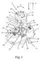
- Fig. 1 designed as a control unit light control unit 1 is shown for a motor vehicle in a partial exploded view.
- the light control unit 1 comprises an electrical switch 2 for switching the illumination of the motor vehicle.
- the light control unit 1 has a housing 3, from which protrudes an actuator 4 for operating the electrical switch 2 by the user.
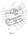
- the housing 3 is still a visible in Fig. 4 contact system 5, which is encapsulated to prevent contamination.
- the contact system 5 is switchable by means of the actuating member 4.
- the actuator 4 is so designed that by the action of a force exceeding a threshold force on the actuator 4, this at least partially in the housing 3 is retractable. As useful for automotive applications, it has been found that the threshold for the force is about 300 to 400 Newton.
- the electrical switch 2 is a rotary latching switch, in which the actuating member 4 is rotatably mounted in the housing 3.
- the trained in the manner of a knob actuator 4 is surrounded by a diaphragm 33.
- the contact system 5 is thus switched by a manual rotational movement of the actuator 4 according to arrow 6 by the user.
- the actuating member 4 a arranged in the housing 3 shaft 14 and an axis 14, wherein the shaft 14 engages a visible in Fig. 3 rotor 15 such that the rotor 15 is rotatable by means of the actuating member 4.
- the rotor 15 is in turn rotatably mounted in a housing 3 located in the holder 17 and acts by means of a spring-loaded plunger 18 with a latching curve 19 in the holder 17 for fixing the locking positions together.
- the rotor 15 in turn actuates the contact system 5 by means of a projection 16 which engages in a visible in Fig. 4 receptacle 36 on the contact system 5.
- the shaft 14 is mounted on the actuating member 4 in a sleeve-like projection 20 on a holding part 35 in the housing 3.
- the actuating member 4 is now in the axial direction corresponding to the arrow 7 with respect to the rotational movement, and thus approximately perpendicular to the surface 8 of the housing 3, on which the actuator 4 protrudes, for sinking into the housing 3 movable.
- the shaft 14 is axially displaceable against the rotor 15 by the sleeve-shaped shaft 14 a Wave 21 engages over the rotor 15, as can be seen from the two FIGS. 1 and 3.
- the shaft 21 and the sleeve-shaped shaft 14 are designed similarly profiled in the rest, in order to allow rotation of the rotor 15 by means of the actuator 4 despite the axial displaceability of the shaft 14. If the actuator 4 recessed in the housing 3, so this can be moved out of the housing 3 again by a tensile force applied by the user in the opposite direction to the sinking according to the arrow 7 '. The movement in the axial direction according to arrow 7 'then takes place until the actuator 4 returns to its original, protruding from the housing 3 position in which the actuator 4 is then held.
- a spring element 9 is fixed with one end in the housing 3 according to the first embodiment shown in FIG. With its other free end, the spring element 9 cooperates with the actuating member 4.
- the actuating member 4 is held in the protruding from the housing 3 position, wherein the actuating member 4 is freely rotatable at the same time for switching the contact system 5.
- the spring element 9 releases the actuating member 4 when the threshold force is exceeded, so that it can dip into the housing 3.
- the spring element 9 is designed in the manner of an approximately U-shaped leg spring.
- the leg spring 9 is attached to the base 11 of the U to latching hooks 12 which are located on the holding part 35 in the housing 3 verclipsend.
- the two free legs 10, 10 'of the U's of the leg spring 9 extend approximately perpendicular to the axial direction 7, 7' and project through an opening 22 into the holding part 35.
- the legs 10, 10 'rest on the holding part 35 and engage in the holding part 35 in a groove 13 on the actuating member 4, namely on the shaft 14 and visible in FIG. 6, by exerting an elastic clamping force. Due to this clamping force, the actuator 4 is held in its protruding from the housing 3 position.
- the compact arrangement half in the housing 3, the legs 10, 10 ' may be provided with a bend 37, as shown in Fig. 6.
- the groove 13 encircling the shaft 14 is provided with a slope in the manner of an inclined plane.
- the threshold value for the immersion force can thus be varied as desired.
- a variable immersion and retraction force for the actuator 4 can be realized by a modified geometry of the groove 13 and / or spring force of the legs 10, 10 'and / or choice of material for the spring element 9. It should be emphasized, however, that the feel of the user felt for the rotation of the actuator 4 by the spring element 9 remains essentially unaffected.
- further switches with contact systems 23 may be arranged in and / or on the housing 3 of the light control unit 1, for example in order to switch the parking lights on the motor vehicle.
- the actuators 24 for the contact systems 23 are designed as push buttons. Likewise, these actuators may be formed in the manner of rockers, which is not shown further.
- visible potentiometer 25 for example, for headlamp leveling of the motor vehicle and / or a dimming function of the light control unit 1.
- the potentiometer 25 are operated by knurled wheels 26 as actuators by the user.
- controls in the light control unit 1 may be arranged so that other other switching functions in addition to the rotation, which can be effected by means of the actuator 4, and the aforementioned switching functions are actuated by the user.
- the housing 3 consists of an upper part 38 and a lower part 39, which are interconnected by screws 40.
- a printed circuit board 27 is arranged for receiving the at least one contact system 5. If available, there are expediently also the other contact systems 23 and The potentiometer 25 and / or the other electrical / electronic components on the printed circuit board 27. If desired, on the circuit board 27 electronics, such as a microprocessor, for processing the switching signals of the contact systems 5, 23 and the potentiometer 25 and optionally for generating bus signals located.
- a standing with the circuit board 27 via connecting pins 34 in electrical connection electrical connection 28 is arranged for a bus system.
- the switching signals of the contact systems 5, 23 and the potentiometer 25 can also be forwarded directly via the terminal 28 to a control device for automotive lighting, so that in this case can be dispensed with a corresponding electronics for processing the switching signals in the light control unit 1 ,
- a control device for automotive lighting so that in this case can be dispensed with a corresponding electronics for processing the switching signals in the light control unit 1
- visible on the circuit board 27 in Fig. 4 visible light emitting diodes 29, 29 'for illuminating shown in Fig. 1 symbols 30, 31 o.
- the like On the actuators 4, 24, 26 and / or on the housing 3 and / or at the aperture 33 to allow the user an appropriate orientation.
- the light emitted by the light-emitting diodes 29 can be guided via light-guiding elements 32 to the associated symbols 30 or displays 31.
- a light control unit 1 according to a further, second exemplary embodiment is shown in a perspective view in FIG. 7.
- this light control unit 1 no spring element 9 is used, but otherwise it is designed substantially the same as that of the first embodiment, so that here also for clarity, Figs. 2 to 4 can be used.
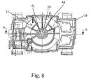
- the spring element 9 are in this further embodiment in the sleeve-like projection 20 of the housing 3 snap and / or latching hooks 41, as can be seen with reference to FIG. 8 or 9, to the actuator 4 in the protruding from the housing 3 position hold.
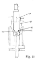
- the snap-in and / or snap-in hooks 41 engage in a groove 42 visible in FIG. 10 on the axis 14.
- a groove 42 visible in FIG. 10 on the axis 14.
- the groove 42 is designed for the purpose of adjusting the threshold value as a one-sided inclined plane.
- the spring element 9 shown in Fig. 5 is suitably made of metal.
- the visible in Fig. 9 snap and / or snap hooks 41 are made of plastic. Since the housing 3 is likewise made of plastic, the snap-in and / or latching hooks 41 can be integrally molded onto the sleeve-like attachment 20 when the upper part 38 of the housing 3 is produced.
- the snap and / or snap hooks 41 are, as can be seen with reference to FIG. 9, arranged in the interior of the sleeve-shaped projection 20 that a possibility of movement in approximately transverse to the axial direction 7, 7 'is given to the Aufsp Soniana the snap - And / or locking hooks 41 to allow.
- On the axis 14 is a stop 43, as can be seen in Fig. 10, which serves to limit the movement of the axis 14 in the axial direction 7, 7 '.
- the sleeve-shaped projection 20 is provided with stiffening ribs 44 located in the housing 3.
- the invention is not limited to the described and illustrated embodiment. Rather, it also encompasses all expert developments within the scope of the invention defined by the claims. Thus, the invention can not only be used on electrical switches for motor vehicles, but also on switches with a retractable actuator for household appliances, machine tools, power tools o. The like. Use find.
Landscapes
- Engineering & Computer Science (AREA)
- Mechanical Engineering (AREA)
- Combustion & Propulsion (AREA)
- Automation & Control Theory (AREA)
- General Physics & Mathematics (AREA)
- Chemical & Material Sciences (AREA)
- Physics & Mathematics (AREA)
- Transportation (AREA)
- Rotary Switch, Piano Key Switch, And Lever Switch (AREA)
- Push-Button Switches (AREA)
- Switch Cases, Indication, And Locking (AREA)
- Slide Switches (AREA)
- Control Of Electric Motors In General (AREA)
- Relay Circuits (AREA)
- Control Of Eletrric Generators (AREA)
Claims (11)
- Commutateur électrique, en particulier pour un véhicule automobile, comme pour une unité de commande de l'éclairage (1) dans un véhicule automobile, comprenant un boîtier (3), un organe d'actionnement (4) sortant du boîtier (3), et dans le boîtier (3) un système de contacts (5) commutable au moyen de l'organe d'actionnement (4), l'organe d'actionnement (4) pouvant être enfoncé sous l'action d'une force dépassant une valeur de seuil, et dans lequel l'organe d'actionnement (4) enfoncé peut être retiré par une force de traction dans le sens (7') contraire à l'enfoncement, de façon à retrouver après son enfoncement et l'extraction qui suit, sa position initiale sortante,
caractérisé en ce que
l'organe d'actionnement (4) peut être enfoncé au moins partiellement dans le boîtier (3), et l'organe d'actionnement (4) coopère avec un élément de ressort (9) dans le boîtier (3) ou avec des crochets d'accrochage et/ou d'encliquetage (41) de telle manière que d'une part l'organe d'actionnement (4) est maintenu dans la position sortant du boîtier (3), notamment en pouvant tourner librement, et que d'autre part l'organe d'actionnement (4) est libéré pour son enfoncement lors du dépassement de la force de seuil. - Commutateur électrique selon la revendication 1,
caractérisé en ce que
l'organe d'actionnement (4) est logé en pouvant tourner dans le boîtier (3) de préférence au moyen d'un arbre (14), d'un axe (14) ou analogue, en particulier à la manière d'un commutateur rotatif, de telle manière que le système de contacts (5) soit commuté par un mouvement de rotation de l'organe d'actionnement (4), et pour son enfoncement dans le boîtier (3), l'organe d'actionnement (4) est de préférence mobile dans la direction axiale (7) par rapport au mouvement de rotation (6), en particulier sensiblement perpendiculairement à la surface (8) du boîtier (3) par laquelle l'organe d'actionnement (4) sort. - Commutateur électrique selon la revendication 1 ou 2,
caractérisé en ce qu'
un élément de ressort (9) est fixé avec une extrémité dans le boîtier (3) et coopère par son autre extrémité libre avec l'organe d'actionnement (4). - Commutateur électrique selon la revendication 1, 2 ou 3,
caractérisé en ce que
l'élément de ressort (9) est réalisé à la manière d'un ressort à branches sensiblement en forme de U, de préférence un ressort à branches (9) est fixé dans le boîtier (3) à la base (11) du U, et plus préférablement les deux branches libres, éventuellement coudées (10, 10') du U s'engagent avec une force de serrage élastique dans une rainure (13) de l'organe d'actionnement (4). - Commutateur électrique selon l'une des revendications 1 à 4,
caractérisé en ce que
l'organe d'actionnement (4) présente un arbre (14), un axe (14) ou analogue disposés dans le boîtier (3), de préférence l'arbre (14), l'axe (14) ou analogue sont en contact avec un rotor (15) actionnant le système de contacts (5), de telle manière que d'une part le rotor (15) puisse tourner au moyen de l'organe d'actionnement (4) et que d'autre part l'arbre (14), l'axe (14) ou analogue puissent coulisser axialement contre le rotor (15), et de préférence la rainure (13) destinée à recevoir les branches (10, 10') du ressort à branches (9) se trouve sur l'arbre (14), l'axe (14) ou analogue. - Commutateur électrique selon l'une des revendications 1 à 5,
caractérisé en ce que
le rotor (15) est monté en rotation dans un support (17) se trouvant dans le boîtier (3), de préférence le rotor (15) coopère au moyen d'un poussoir à ressort (18) avec une came crantée (19) pour la fixation des positions d'encliquetage, en outre préférablement l'arbre (14), l'axe (14) ou analogue sont montés dans une saillie en forme de douille (20) sur une pièce de maintien (35) dans le boîtier (3), et encore de préférence les branches (10, 10') du ressort à branches (9) pénètrent à travers une ouverture (22) dans la pièce de maintien (35) pour s'engager dans la rainure (13) de l'arbre (14). - Commutateur électrique selon l'une des revendications 1 à 6,
caractérisé en ce que
des organes d'actionnement (24, 26), en particulier du type boutons-poussoirs, bascules, boutons moletés ou analogues, pour des systèmes de contacts (23) d'autres commutateurs, pour des potentiomètres (25) ou analogues, sont disposés dans et/ou sur le boîtier (3), pour pouvoir commander d'autres fonctions de commutation en plus de la commutation rotative réalisable au moyen de l'organe d'actionnement (4). - Commutateur électrique selon l'une des revendications 1 à 7,
caractérisé en ce qu'
une plaquette de circuits imprimés (27) est disposée dans le boîtier (3) pour recevoir au moins un système de contacts (5, 23), le potentiomètre (25) ou analogues, de préférence un dispositif électronique se trouve sur la plaquette de circuits imprimés (27) pour traiter les signaux de commutation ainsi que pour produire éventuellement des signaux de bus, en outre préférablement un raccord (28) en liaison électrique avec la plaquette de circuits imprimés (27) est disposé sur le boîtier (3), notamment pour un système de bus, et de plus de préférence des diodes électroluminescentes (29, 29') se trouvent sur la plaquette de circuits imprimés (27) pour un éclairage, notamment à l'aide de guides de lumière (32), de symboles (30), d'informations (31) ou analogues sur les organes d'actionnement (4, 24, 26) et/ou sur le boîtier (3). - Commutateur électrique selon l'une des revendications 1 à 8,
caractérisé en ce que
les crochets d'accrochage et/ou d'encliquetage (41) se trouvent dans une saillie en forme de douille (20) dans le boîtier (3), de préférence l'axe (14) guidé notamment dans la saillie en forme de douille (20) est maintenu au moyen des crochets d'accrochage et/ou d'encliquetage (41) dans la position dans laquelle l'organe d'actionnement (4) sort du boîtier (3), notamment en pouvant tourner librement, de plus préférablement les crochets d'accrochage et/ou d'encliquetage (41) s'engagent dans une rainure (42) sur l'axe (14), et encore de préférence un dépassement de la force de seuil entraîne une expansion des crochets d'accrochage et/ou d'encliquetage (41) libérant l'axe (14) pour pouvoir enfoncer l'organe d'actionnement (4) dans le boîtier (3). - Commutateur électrique selon l'une des revendications 1 à 9,
caractérisé en ce que
l'élément de ressort (9) est en métal. - Commutateur électrique selon l'une des revendications 1 à 9,
caractérisé en ce que
les crochets d'accrochage et/ou d'encliquetage (41) sont formés par injection de plastique notamment d'une seule pièce sur la pièce en forme de douille (20), de préférence les crochets d'accrochage et/ou d'encliquetage (41) sont à l'intérieur de la saille en forme de douille (20) pour pouvoir être mobiles sensiblement transversalement à la direction axiale (7, 7') en vue de leur expansion, de plus préférablement une butée (43) est prévue sur l'axe (14) pour limiter le mouvement de l'axe (14) dans la direction axiale (7, 7'), et encore de préférence la saillie en forme de douille (20) est pourvue de nervures de renforcement (44) à l'intérieur du boîtier (3).
Applications Claiming Priority (4)
| Application Number | Priority Date | Filing Date | Title |
|---|---|---|---|
| DE10304036 | 2003-02-01 | ||
| DE10304036 | 2003-02-01 | ||
| DE10341017 | 2003-09-03 | ||
| DE10341017 | 2003-09-03 |
Publications (3)
| Publication Number | Publication Date |
|---|---|
| EP1443533A2 EP1443533A2 (fr) | 2004-08-04 |
| EP1443533A3 EP1443533A3 (fr) | 2005-09-21 |
| EP1443533B1 true EP1443533B1 (fr) | 2007-02-28 |
Family
ID=32657778
Family Applications (1)
| Application Number | Title | Priority Date | Filing Date |
|---|---|---|---|
| EP04001931A Expired - Lifetime EP1443533B1 (fr) | 2003-02-01 | 2004-01-29 | Commutateurs électriques |
Country Status (3)
| Country | Link |
|---|---|
| EP (1) | EP1443533B1 (fr) |
| AT (1) | ATE355600T1 (fr) |
| DE (2) | DE102004004471A1 (fr) |
Cited By (1)
| Publication number | Priority date | Publication date | Assignee | Title |
|---|---|---|---|---|
| US12030428B1 (en) * | 2022-12-29 | 2024-07-09 | Hyundai Mobis Co., Ltd. | Pillar module |
Families Citing this family (6)
| Publication number | Priority date | Publication date | Assignee | Title |
|---|---|---|---|---|
| GB0418358D0 (en) * | 2004-08-18 | 2004-09-22 | Ford Global Tech Llc | Selector mechanism for a motor vehicle transmission |
| DE102004054178B4 (de) * | 2004-11-10 | 2010-09-02 | Preh Gmbh | Bedienelement für Steuergeräte in Kraftfahrzeugen |
| FR2879843B1 (fr) * | 2004-12-21 | 2008-08-22 | Sc2N Sa | Dispositif de commande de commutation pour vehicule automobile |
| DE102013208640B4 (de) | 2013-05-10 | 2019-03-28 | GSI Glastechnologie GmbH | Bedienvorrichtung mit einer Basisplatte aus einem nichtmagnetischen Material und einem berührungsempfindlichen Sensor |
| DE102014005082B4 (de) | 2014-04-05 | 2026-04-16 | Audi Ag | Kontrollgerät zum Kontrollieren mindestens einer Außenbeleuchtungsvorrichtung |
| US9881752B2 (en) | 2015-12-02 | 2018-01-30 | Kabushiki Kaisha Tokai Rika Denki Seisakusho | Rotary-type switch |
Family Cites Families (3)
| Publication number | Priority date | Publication date | Assignee | Title |
|---|---|---|---|---|
| US4051916A (en) * | 1975-12-22 | 1977-10-04 | Nissan Motor Company, Limited | Apparatus for mounting instrument to instrument panel in motor vehicle |
| DE4203427C2 (de) * | 1992-02-06 | 1999-07-08 | Haschkamp Ernestine | Nockendrehschalter |
| DE20120667U1 (de) * | 2001-12-20 | 2002-12-12 | Siemens AG, 80333 München | Deformierbarer Druckknopf |
-
2004
- 2004-01-28 DE DE102004004471A patent/DE102004004471A1/de not_active Withdrawn
- 2004-01-29 DE DE502004002996T patent/DE502004002996D1/de not_active Expired - Lifetime
- 2004-01-29 EP EP04001931A patent/EP1443533B1/fr not_active Expired - Lifetime
- 2004-01-29 AT AT04001931T patent/ATE355600T1/de not_active IP Right Cessation
Cited By (1)
| Publication number | Priority date | Publication date | Assignee | Title |
|---|---|---|---|---|
| US12030428B1 (en) * | 2022-12-29 | 2024-07-09 | Hyundai Mobis Co., Ltd. | Pillar module |
Also Published As
| Publication number | Publication date |
|---|---|
| DE502004002996D1 (de) | 2007-04-12 |
| EP1443533A2 (fr) | 2004-08-04 |
| DE102004004471A1 (de) | 2004-08-05 |
| ATE355600T1 (de) | 2006-03-15 |
| EP1443533A3 (fr) | 2005-09-21 |
Similar Documents
| Publication | Publication Date | Title |
|---|---|---|
| EP0876940B1 (fr) | Interrupteur multifonction à bouton poussoir | |
| DE19844336C1 (de) | Elektrischer Schalter | |
| DE19723482C1 (de) | Elektrischer Dreh-/Schubschalter | |
| EP1443533A2 (fr) | Commutateurs électriques | |
| EP0235350B1 (fr) | Interrupteur, en particulier pour véhicule | |
| DE10040713B4 (de) | Elektrischer Schalter | |
| EP0587056B1 (fr) | Touche basculante | |
| DE10309823B4 (de) | Waschmaschine mit einem Bedienfeld | |
| EP0902448A2 (fr) | Dispositif d'installation électrique, en particulier palpeur, actionneur ou interrupteur | |
| EP0887819A2 (fr) | Commutateur électrique à bouton poussoir | |
| DE69308401T2 (de) | Bedienungstafel mit Berührungstasten für die Regelung einer Klimatisiereinrichtung eines Fahrzeuginnenraums | |
| DE19514539C2 (de) | Mehrfunktionsschalter, insbesondere Spiegelverstellschalter für ein Kraftfahrzeug | |
| EP0897584B1 (fr) | Interrupteur a bascule, en particulier pour le leve-glace d'un vehicule a moteur | |
| EP0675515B1 (fr) | Interrupteur, en particulier pour le montage dans le tableau de bord d'un véhicule automobile, et procédé de fabrication d'un tel interrupteur | |
| DE10259605B3 (de) | Elektrischer Kippschalter | |
| DE4334054C2 (de) | Elektrischer Schalter | |
| DE10254992B4 (de) | Elektrischer Schalter | |
| DE19963144B4 (de) | Selbstjustierenden Stößelschalter | |
| DE10202955B4 (de) | Innenleuchte für ein Kraftfahrzeug | |
| DE10063385A1 (de) | Elektrischer Schalter | |
| DE20305387U1 (de) | Not-Aus-Gerät mit integrierten Schaltelementen | |
| DE3921698C1 (en) | Control or switching appts. - has free-standing end region for multifunctional switching and tubular intermediate section accepting electrical leads | |
| DE19946601C1 (de) | Schaltvorrichtung, insbesondere für eine Gastherme | |
| DE3546625C2 (en) | Electrical rotary switch having illumination | |
| DE4436324B4 (de) | Vorrichtung zum Verstellen eines Schaltrades |
Legal Events
| Date | Code | Title | Description |
|---|---|---|---|
| PUAI | Public reference made under article 153(3) epc to a published international application that has entered the european phase |
Free format text: ORIGINAL CODE: 0009012 |
|
| AK | Designated contracting states |
Kind code of ref document: A2 Designated state(s): AT BE BG CH CY CZ DE DK EE ES FI FR GB GR HU IE IT LI LU MC NL PT RO SE SI SK TR |
|
| AX | Request for extension of the european patent |
Extension state: AL LT LV MK |
|
| PUAL | Search report despatched |
Free format text: ORIGINAL CODE: 0009013 |
|
| AK | Designated contracting states |
Kind code of ref document: A3 Designated state(s): AT BE BG CH CY CZ DE DK EE ES FI FR GB GR HU IE IT LI LU MC NL PT RO SE SI SK TR |
|
| AX | Request for extension of the european patent |
Extension state: AL LT LV MK |
|
| RIC1 | Information provided on ipc code assigned before grant |
Ipc: 7H 01R 3/08 B Ipc: 7H 01H 3/00 A |
|
| 17P | Request for examination filed |
Effective date: 20051129 |
|
| AKX | Designation fees paid |
Designated state(s): AT BE BG CH CY CZ DE DK EE ES FI FR GB GR HU IE IT LI LU MC NL PT RO SE SI SK TR |
|
| GRAP | Despatch of communication of intention to grant a patent |
Free format text: ORIGINAL CODE: EPIDOSNIGR1 |
|
| GRAS | Grant fee paid |
Free format text: ORIGINAL CODE: EPIDOSNIGR3 |
|
| GRAA | (expected) grant |
Free format text: ORIGINAL CODE: 0009210 |
|
| AK | Designated contracting states |
Kind code of ref document: B1 Designated state(s): AT BE BG CH CY CZ DE DK EE ES FI FR GB GR HU IE IT LI LU MC NL PT RO SE SI SK TR |
|
| PG25 | Lapsed in a contracting state [announced via postgrant information from national office to epo] |
Ref country code: NL Free format text: LAPSE BECAUSE OF FAILURE TO SUBMIT A TRANSLATION OF THE DESCRIPTION OR TO PAY THE FEE WITHIN THE PRESCRIBED TIME-LIMIT Effective date: 20070228 Ref country code: DK Free format text: LAPSE BECAUSE OF FAILURE TO SUBMIT A TRANSLATION OF THE DESCRIPTION OR TO PAY THE FEE WITHIN THE PRESCRIBED TIME-LIMIT Effective date: 20070228 Ref country code: SI Free format text: LAPSE BECAUSE OF FAILURE TO SUBMIT A TRANSLATION OF THE DESCRIPTION OR TO PAY THE FEE WITHIN THE PRESCRIBED TIME-LIMIT Effective date: 20070228 Ref country code: FI Free format text: LAPSE BECAUSE OF FAILURE TO SUBMIT A TRANSLATION OF THE DESCRIPTION OR TO PAY THE FEE WITHIN THE PRESCRIBED TIME-LIMIT Effective date: 20070228 Ref country code: IE Free format text: LAPSE BECAUSE OF FAILURE TO SUBMIT A TRANSLATION OF THE DESCRIPTION OR TO PAY THE FEE WITHIN THE PRESCRIBED TIME-LIMIT Effective date: 20070228 |
|
| REG | Reference to a national code |
Ref country code: GB Ref legal event code: FG4D Free format text: NOT ENGLISH |
|
| REG | Reference to a national code |
Ref country code: CH Ref legal event code: EP |
|
| REF | Corresponds to: |
Ref document number: 502004002996 Country of ref document: DE Date of ref document: 20070412 Kind code of ref document: P |
|
| REG | Reference to a national code |
Ref country code: IE Ref legal event code: FG4D Free format text: LANGUAGE OF EP DOCUMENT: GERMAN |
|
| PG25 | Lapsed in a contracting state [announced via postgrant information from national office to epo] |
Ref country code: BG Free format text: LAPSE BECAUSE OF EXPIRATION OF PROTECTION Effective date: 20070529 |
|
| PG25 | Lapsed in a contracting state [announced via postgrant information from national office to epo] |
Ref country code: SE Free format text: LAPSE BECAUSE OF FAILURE TO SUBMIT A TRANSLATION OF THE DESCRIPTION OR TO PAY THE FEE WITHIN THE PRESCRIBED TIME-LIMIT Effective date: 20070531 |
|
| PG25 | Lapsed in a contracting state [announced via postgrant information from national office to epo] |
Ref country code: ES Free format text: LAPSE BECAUSE OF FAILURE TO SUBMIT A TRANSLATION OF THE DESCRIPTION OR TO PAY THE FEE WITHIN THE PRESCRIBED TIME-LIMIT Effective date: 20070608 |
|
| PG25 | Lapsed in a contracting state [announced via postgrant information from national office to epo] |
Ref country code: PT Free format text: LAPSE BECAUSE OF FAILURE TO SUBMIT A TRANSLATION OF THE DESCRIPTION OR TO PAY THE FEE WITHIN THE PRESCRIBED TIME-LIMIT Effective date: 20070730 |
|
| NLV1 | Nl: lapsed or annulled due to failure to fulfill the requirements of art. 29p and 29m of the patents act | ||
| GBV | Gb: ep patent (uk) treated as always having been void in accordance with gb section 77(7)/1977 [no translation filed] |
Effective date: 20070228 |
|
| REG | Reference to a national code |
Ref country code: IE Ref legal event code: FD4D |
|
| EN | Fr: translation not filed | ||
| PG25 | Lapsed in a contracting state [announced via postgrant information from national office to epo] |
Ref country code: SK Free format text: LAPSE BECAUSE OF FAILURE TO SUBMIT A TRANSLATION OF THE DESCRIPTION OR TO PAY THE FEE WITHIN THE PRESCRIBED TIME-LIMIT Effective date: 20070228 Ref country code: GB Free format text: LAPSE BECAUSE OF FAILURE TO SUBMIT A TRANSLATION OF THE DESCRIPTION OR TO PAY THE FEE WITHIN THE PRESCRIBED TIME-LIMIT Effective date: 20070228 |
|
| PG25 | Lapsed in a contracting state [announced via postgrant information from national office to epo] |
Ref country code: CZ Free format text: LAPSE BECAUSE OF FAILURE TO SUBMIT A TRANSLATION OF THE DESCRIPTION OR TO PAY THE FEE WITHIN THE PRESCRIBED TIME-LIMIT Effective date: 20070228 Ref country code: RO Free format text: LAPSE BECAUSE OF FAILURE TO SUBMIT A TRANSLATION OF THE DESCRIPTION OR TO PAY THE FEE WITHIN THE PRESCRIBED TIME-LIMIT Effective date: 20070228 |
|
| PLBE | No opposition filed within time limit |
Free format text: ORIGINAL CODE: 0009261 |
|
| STAA | Information on the status of an ep patent application or granted ep patent |
Free format text: STATUS: NO OPPOSITION FILED WITHIN TIME LIMIT |
|
| 26N | No opposition filed |
Effective date: 20071129 |
|
| PG25 | Lapsed in a contracting state [announced via postgrant information from national office to epo] |
Ref country code: IT Free format text: LAPSE BECAUSE OF FAILURE TO SUBMIT A TRANSLATION OF THE DESCRIPTION OR TO PAY THE FEE WITHIN THE PRESCRIBED TIME-LIMIT Effective date: 20070228 Ref country code: FR Free format text: LAPSE BECAUSE OF FAILURE TO SUBMIT A TRANSLATION OF THE DESCRIPTION OR TO PAY THE FEE WITHIN THE PRESCRIBED TIME-LIMIT Effective date: 20071019 Ref country code: GR Free format text: LAPSE BECAUSE OF FAILURE TO SUBMIT A TRANSLATION OF THE DESCRIPTION OR TO PAY THE FEE WITHIN THE PRESCRIBED TIME-LIMIT Effective date: 20070529 |
|
| BERE | Be: lapsed |
Owner name: MARQUARDT G.M.B.H. Effective date: 20080131 |
|
| PG25 | Lapsed in a contracting state [announced via postgrant information from national office to epo] |
Ref country code: MC Free format text: LAPSE BECAUSE OF NON-PAYMENT OF DUE FEES Effective date: 20080131 |
|
| REG | Reference to a national code |
Ref country code: CH Ref legal event code: PL |
|
| PG25 | Lapsed in a contracting state [announced via postgrant information from national office to epo] |
Ref country code: CH Free format text: LAPSE BECAUSE OF NON-PAYMENT OF DUE FEES Effective date: 20080131 Ref country code: LI Free format text: LAPSE BECAUSE OF NON-PAYMENT OF DUE FEES Effective date: 20080131 |
|
| PG25 | Lapsed in a contracting state [announced via postgrant information from national office to epo] |
Ref country code: FR Free format text: LAPSE BECAUSE OF FAILURE TO SUBMIT A TRANSLATION OF THE DESCRIPTION OR TO PAY THE FEE WITHIN THE PRESCRIBED TIME-LIMIT Effective date: 20070228 |
|
| PG25 | Lapsed in a contracting state [announced via postgrant information from national office to epo] |
Ref country code: EE Free format text: LAPSE BECAUSE OF FAILURE TO SUBMIT A TRANSLATION OF THE DESCRIPTION OR TO PAY THE FEE WITHIN THE PRESCRIBED TIME-LIMIT Effective date: 20070228 |
|
| PG25 | Lapsed in a contracting state [announced via postgrant information from national office to epo] |
Ref country code: BE Free format text: LAPSE BECAUSE OF NON-PAYMENT OF DUE FEES Effective date: 20080131 |
|
| PG25 | Lapsed in a contracting state [announced via postgrant information from national office to epo] |
Ref country code: AT Free format text: LAPSE BECAUSE OF NON-PAYMENT OF DUE FEES Effective date: 20080129 |
|
| PG25 | Lapsed in a contracting state [announced via postgrant information from national office to epo] |
Ref country code: CY Free format text: LAPSE BECAUSE OF FAILURE TO SUBMIT A TRANSLATION OF THE DESCRIPTION OR TO PAY THE FEE WITHIN THE PRESCRIBED TIME-LIMIT Effective date: 20070228 |
|
| PG25 | Lapsed in a contracting state [announced via postgrant information from national office to epo] |
Ref country code: LU Free format text: LAPSE BECAUSE OF NON-PAYMENT OF DUE FEES Effective date: 20080129 Ref country code: HU Free format text: LAPSE BECAUSE OF FAILURE TO SUBMIT A TRANSLATION OF THE DESCRIPTION OR TO PAY THE FEE WITHIN THE PRESCRIBED TIME-LIMIT Effective date: 20070901 |
|
| PG25 | Lapsed in a contracting state [announced via postgrant information from national office to epo] |
Ref country code: TR Free format text: LAPSE BECAUSE OF FAILURE TO SUBMIT A TRANSLATION OF THE DESCRIPTION OR TO PAY THE FEE WITHIN THE PRESCRIBED TIME-LIMIT Effective date: 20070228 |
|
| REG | Reference to a national code |
Ref country code: DE Ref legal event code: R082 Ref document number: 502004002996 Country of ref document: DE Representative=s name: PATENTANWAELTE STAEGER & SPERLING PARTNERSCHAF, DE Ref country code: DE Ref legal event code: R082 Ref document number: 502004002996 Country of ref document: DE Ref country code: DE Ref legal event code: R082 Ref document number: 502004002996 Country of ref document: DE Representative=s name: JOSTARNDT PATENTANWALTS-AG, DE |
|
| REG | Reference to a national code |
Ref legal event code: R082 Ref document number: 502004002996 Representative=s name: PATENTANWAELTE STAEGER & SPERLING PARTNERSCHAF, DE Ref country code: DE Country of ref document: DE |
|
| REG | Reference to a national code |
Ref country code: DE Ref legal event code: R082 Ref document number: 502004002996 Country of ref document: DE Representative=s name: PATENTANWAELTE STAEGER & SPERLING PARTNERSCHAF, DE |
|
| PGFP | Annual fee paid to national office [announced via postgrant information from national office to epo] |
Ref country code: DE Payment date: 20230119 Year of fee payment: 20 |
|
| P01 | Opt-out of the competence of the unified patent court (upc) registered |
Effective date: 20230522 |
|
| REG | Reference to a national code |
Ref country code: DE Ref legal event code: R071 Ref document number: 502004002996 Country of ref document: DE |