EP1443589A1 - Transition entre un circuit à microbande et un guide d'ondes et élément de transmission/réception extérieur l'utilisant - Google Patents
Transition entre un circuit à microbande et un guide d'ondes et élément de transmission/réception extérieur l'utilisant Download PDFInfo
- Publication number
- EP1443589A1 EP1443589A1 EP04100108A EP04100108A EP1443589A1 EP 1443589 A1 EP1443589 A1 EP 1443589A1 EP 04100108 A EP04100108 A EP 04100108A EP 04100108 A EP04100108 A EP 04100108A EP 1443589 A1 EP1443589 A1 EP 1443589A1
- Authority
- EP
- European Patent Office
- Prior art keywords
- transition
- waveguide
- frequency
- local oscillator
- cavity
- Prior art date
- Legal status (The legal status is an assumption and is not a legal conclusion. Google has not performed a legal analysis and makes no representation as to the accuracy of the status listed.)
- Granted
Links
- 230000007704 transition Effects 0.000 title claims abstract description 40
- 230000005540 biological transmission Effects 0.000 title claims abstract description 14
- 238000005516 engineering process Methods 0.000 claims abstract description 10
- 239000000523 sample Substances 0.000 claims abstract description 6
- 238000004519 manufacturing process Methods 0.000 claims description 9
- 230000010355 oscillation Effects 0.000 claims description 2
- 239000000758 substrate Substances 0.000 description 5
- 230000006854 communication Effects 0.000 description 2
- 238000004891 communication Methods 0.000 description 2
- 230000008878 coupling Effects 0.000 description 2
- 238000010168 coupling process Methods 0.000 description 2
- 238000005859 coupling reaction Methods 0.000 description 2
- 238000001914 filtration Methods 0.000 description 2
- 238000003754 machining Methods 0.000 description 2
- 230000002238 attenuated effect Effects 0.000 description 1
- 230000007175 bidirectional communication Effects 0.000 description 1
- 230000002457 bidirectional effect Effects 0.000 description 1
- 230000000694 effects Effects 0.000 description 1
- 238000000465 moulding Methods 0.000 description 1
- 230000017105 transposition Effects 0.000 description 1
Images


Classifications
-
- H—ELECTRICITY
- H01—ELECTRIC ELEMENTS
- H01P—WAVEGUIDES; RESONATORS, LINES, OR OTHER DEVICES OF THE WAVEGUIDE TYPE
- H01P1/00—Auxiliary devices
- H01P1/20—Frequency-selective devices, e.g. filters
- H01P1/207—Hollow waveguide filters
- H01P1/209—Hollow waveguide filters comprising one or more branching arms or cavities wholly outside the main waveguide
-
- H—ELECTRICITY
- H01—ELECTRIC ELEMENTS
- H01P—WAVEGUIDES; RESONATORS, LINES, OR OTHER DEVICES OF THE WAVEGUIDE TYPE
- H01P5/00—Coupling devices of the waveguide type
- H01P5/08—Coupling devices of the waveguide type for linking dissimilar lines or devices
- H01P5/10—Coupling devices of the waveguide type for linking dissimilar lines or devices for coupling balanced lines or devices with unbalanced lines or devices
- H01P5/107—Hollow-waveguide/strip-line transitions
Definitions
- the invention pertains to a transition between a microstrip circuit and a waveguide. More particularly, the transition which is the subject of the invention corresponds to a transition for a transmit circuit of an outside transmit/receive unit. The invention pertains also to the outside transmit/receive unit.
- bidirectional-satellite transmissions being called on to develop within the mass market sector, low-cost solutions are currently being sought so as to be able to disseminate them on a large scale.
- a known problem is compliance with the transmission standards defined by the public organizations for allocating frequency that demand that the signals transmitted should come within a specific template.
- Another known problem relates to the coupling between transmission and reception. Specifically, the same antenna being used both for transmission and for reception, the high-power transmitted signals will disturb the low-power received signals. Although the transmit and receive bands are disjoint, it is necessary to have good filtering on reception in order to reduce the saturation of the low noise amplifier.
- the local oscillator used for transmission may be at a frequency lying very near the transmission band and precludes the possibility of an effective bandpass filter for so close a frequency. Furthermore, the signal corresponding to the local oscillator is as amplified as the transmitted signal. It is known to use an additional bandstop filter to attenuate the frequency line corresponding to the local oscillator.
- Figure 1 represents an exemplary outside unit 1 according to the state of the art.
- a bandpass filter 4 selects the transmission band and attenuates the signal corresponding to the frequency of the local oscillator 2.
- bandstop filter 5 to attenuate the signal corresponding to the frequency of the local oscillator 2 by at least 50 dB.
- a power amplifier 6 then amplifies the signal to be transmitted before the latter is transformed into an electromagnetic wave by a transition between a microstrip technology circuit and a waveguide 8 linked to a horn 9.
- the use of the bandstop filter 5 has the effect of eliminating the component corresponding to the local oscillator 2.
- the frequency of the local oscillator 2 is no longer a nuisance in respect of transmission. Moreover, the possible echo of the signal corresponding to the frequency of the local oscillator 2 being greatly attenuated, it intervenes all the less in the saturation of the low noise amplifier of the reception circuit.
- the embodying of a microstrip technology filter requires a lengthening of the microstrip lines and the addition of amplifiers 11 and 12. Microstrip technology does not permit a good quality factor to be obtained in respect of the embodying of the bandstop filter 5. It is relatively difficult to have 50 dB of attenuation, this requiring the constraints on the bandpass filter 4 to be increased.
- the invention proposes to remedy the problem related to the bandstop filter by introducing one or more resonant cavities at the level of the transition between the microstrip circuit and the waveguide.
- the first cavity is dimensioned to resonate at a determined frequency so that the transition behaves as a bandstop filter for the said determined frequency.
- the guide is of rectangular section and the hole is a slot.
- the invention is also an outside unit of a transmission/reception system comprising a transmit circuit embodied in microstrip technology and a transmission/reception antenna of waveguide type, the transmit circuit comprising at least one local oscillator.
- the unit comprises a transition as defined above between the transmit circuit and the antenna.
- the resonant frequency of the cavity corresponds to the frequency of oscillation of the local oscillator, to within a manufacturing tolerance.
- the resonant frequencies of the two cavities are placed on either side of the frequency of the local oscillator.
- figure 2 represents an outside unit according to the invention
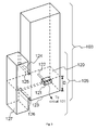
- FIGS. 3 and 4 represent a first embodiment of a transition according to the invention
- the transition 105 includes a bandstop filter for rejecting the frequency of the local oscillator 107.
- Figures 3 and 4 show a first embodiment of a transition 105 according to the invention.
- Figure 3 represents the active contours of the transition and figure 4 represents an exploded cross-sectional view of the transition.
- the transition 105 forms the junction between the waveguide 103 and the transmit circuit 101 which is not represented in the figures but which is supported by the substrate 120.
- a microstrip line 121 carried by the substrate 120 and linked to the transmit circuit 102 is transformed into a probe 122 inside the guide.
- the substrate 120 is placed a distance D from a bottom 123 of the waveguide 103, D being an odd multiple of a quarter of the wavelength guided by the waveguide 103.
- a slot 124 delimited by two ledges 125 and 126 is placed on one side at the waveguide 103 at the level of the substrate 120. This slot 124 emerges into a cavity 127.
- the cavity 127 is dimensioned so that it has a resonant frequency that is substantially equal to the frequency of the local oscillator 107. The presence of the cavity 127 acts as a frequency trap and behaves as a bandstop filter of very good quality.
- a production difficulty stems from the tolerances on the dimensions of the cavity 127. This cavity must be machined accurately enough for the resonant frequency to be very close (ideally equal) to the frequency of the local oscillator. Now, such machining accuracy may seem expensive for mass production.
- a second cavity 128 coupled to the guide 103 by a second slot 129 is added at the level of the transition 105.
- the second slot 129 is centred with respect to the substrate 120 and placed on a side of the waveguide 103 which is for example opposite from the first slot 124.
- the first and second cavities 127 and 128 are dimensioned so that their resonant frequencies are situated on either side of the frequency of the local oscillator 107 and spaced apart by a frequency band slightly greater than the variation in frequency that results from the manufacturing tolerance of the said cavities 127 and 128.
- a bandstop filter is produced for the frequency of the local oscillator 107 while being able to use less expensive manufacturing tolerances.
Landscapes
- Control Of Motors That Do Not Use Commutators (AREA)
- Transceivers (AREA)
- Input Circuits Of Receivers And Coupling Of Receivers And Audio Equipment (AREA)
- Waveguide Aerials (AREA)
Applications Claiming Priority (2)
| Application Number | Priority Date | Filing Date | Title |
|---|---|---|---|
| FR0301429A FR2850793A1 (fr) | 2003-01-31 | 2003-01-31 | Transition entre un circuit micro-ruban et un guide d'onde et unite exterieure d'emission reception incorporant la transition |
| FR0301429 | 2003-01-31 |
Publications (2)
| Publication Number | Publication Date |
|---|---|
| EP1443589A1 true EP1443589A1 (fr) | 2004-08-04 |
| EP1443589B1 EP1443589B1 (fr) | 2011-04-20 |
Family
ID=32606014
Family Applications (1)
| Application Number | Title | Priority Date | Filing Date |
|---|---|---|---|
| EP04100108A Expired - Lifetime EP1443589B1 (fr) | 2003-01-31 | 2004-01-15 | Transition entre un circuit à microbande et un guide d'ondes et élément de transmission/réception extérieur l'utilisant |
Country Status (7)
| Country | Link |
|---|---|
| US (1) | US7148766B2 (fr) |
| EP (1) | EP1443589B1 (fr) |
| JP (1) | JP4257225B2 (fr) |
| KR (1) | KR100997469B1 (fr) |
| CN (1) | CN100411243C (fr) |
| DE (1) | DE602004032278D1 (fr) |
| FR (1) | FR2850793A1 (fr) |
Cited By (3)
| Publication number | Priority date | Publication date | Assignee | Title |
|---|---|---|---|---|
| WO2009118519A1 (fr) * | 2008-03-25 | 2009-10-01 | Asc Uk Signal Corporation Limited | Filtre de guide d'onde |
| CN108321479A (zh) * | 2018-04-03 | 2018-07-24 | 中国工程物理研究院电子工程研究所 | 一种半槽式天线型芯片-波导传输过渡结构 |
| CN113904076A (zh) * | 2021-12-13 | 2022-01-07 | 成都雷电微晶科技有限公司 | 一种w波段具有镜频抑制特性的h面探针过渡结构 |
Families Citing this family (15)
| Publication number | Priority date | Publication date | Assignee | Title |
|---|---|---|---|---|
| US7603097B2 (en) * | 2004-12-30 | 2009-10-13 | Valeo Radar Systems, Inc. | Vehicle radar sensor assembly |
| US7680464B2 (en) * | 2004-12-30 | 2010-03-16 | Valeo Radar Systems, Inc. | Waveguide—printed wiring board (PWB) interconnection |
| US7463109B2 (en) * | 2005-04-18 | 2008-12-09 | Furuno Electric Company Ltd. | Apparatus and method for waveguide to microstrip transition having a reduced scale backshort |
| JP2007180655A (ja) * | 2005-12-27 | 2007-07-12 | New Japan Radio Co Ltd | 帯域阻止フィルタ内蔵伝送モード変換器 |
| US7420436B2 (en) * | 2006-03-14 | 2008-09-02 | Northrop Grumman Corporation | Transmission line to waveguide transition having a widened transmission with a window at the widened end |
| US7479842B2 (en) * | 2006-03-31 | 2009-01-20 | International Business Machines Corporation | Apparatus and methods for constructing and packaging waveguide to planar transmission line transitions for millimeter wave applications |
| CN101110491B (zh) * | 2006-07-19 | 2011-02-16 | 上海杰盛无线通讯设备有限公司 | 数字微波室外单元中双工器 |
| JP2008079085A (ja) * | 2006-09-22 | 2008-04-03 | Mitsubishi Electric Corp | 伝送線路導波管変換器 |
| RU2355077C1 (ru) * | 2007-07-18 | 2009-05-10 | Федеральное государственное унитарное предприятие "НПП "Дельта" | Полосковая антенна |
| US8008997B2 (en) * | 2007-10-09 | 2011-08-30 | Itt Manufacturing Enterprises, Inc. | Printed circuit board filter having rows of vias defining a quasi cavity that is below a cutoff frequency |
| US9653796B2 (en) | 2013-12-16 | 2017-05-16 | Valeo Radar Systems, Inc. | Structure and technique for antenna decoupling in a vehicle mounted sensor |
| US11047951B2 (en) | 2015-12-17 | 2021-06-29 | Waymo Llc | Surface mount assembled waveguide transition |
| US10693236B2 (en) * | 2016-02-03 | 2020-06-23 | Waymo Llc | Iris matched PCB to waveguide transition |
| EP3523853A1 (fr) * | 2016-10-06 | 2019-08-14 | Telefonaktiebolaget LM Ericsson (PUBL) | Alimentation de guide d'ondes |
| CN115207588A (zh) * | 2021-04-09 | 2022-10-18 | 华为技术有限公司 | 一种转接装置、电子设备、终端和转接装置的制备方法 |
Citations (5)
| Publication number | Priority date | Publication date | Assignee | Title |
|---|---|---|---|---|
| EP0715368A1 (fr) * | 1994-11-28 | 1996-06-05 | Nec Corporation | Convertisseur guide d'ondes-coaxial |
| JPH11330810A (ja) * | 1998-05-20 | 1999-11-30 | Fujitsu General Ltd | Lnb装置 |
| JP2000244211A (ja) * | 1999-02-19 | 2000-09-08 | Nec Corp | 導波管接続パッケージ |
| JP2002118404A (ja) * | 2000-10-06 | 2002-04-19 | New Japan Radio Co Ltd | 送信帯域阻止フィルタ内蔵型衛星通信用周波数コンバータ |
| WO2002071533A1 (fr) * | 2001-03-05 | 2002-09-12 | Saab Ab | Transition de ligne microruban |
Family Cites Families (11)
| Publication number | Priority date | Publication date | Assignee | Title |
|---|---|---|---|---|
| JPS5696505A (en) * | 1979-12-28 | 1981-08-04 | Mitsubishi Electric Corp | Transistor oscillator of parallel operation |
| JPS5999801A (ja) * | 1982-11-30 | 1984-06-08 | Toshiba Corp | マイクロ波受信装置 |
| JPS6351702A (ja) * | 1986-08-21 | 1988-03-04 | Shimada Phys & Chem Ind Co Ltd | 導波管形帯域阻止濾波器 |
| JPH0249202U (fr) * | 1988-09-30 | 1990-04-05 | ||
| US5235300A (en) * | 1992-03-16 | 1993-08-10 | Trw Inc. | Millimeter module package |
| JP3366031B2 (ja) | 1992-11-26 | 2003-01-14 | 松下電器産業株式会社 | 導波管−マイクロストリップ変換器 |
| FR2700066A1 (fr) * | 1992-12-29 | 1994-07-01 | Philips Electronique Lab | Dispositif hyperfréquences comprenant au moins une transition entre une ligne de transmission intégrée sur un substrat et un guide d'onde. |
| JPH07318604A (ja) * | 1994-05-30 | 1995-12-08 | Nec Eng Ltd | 高調波モニタ |
| JPH1065038A (ja) * | 1996-08-22 | 1998-03-06 | Mitsubishi Electric Corp | ミリ波デバイス用パッケージ |
| JP2000332525A (ja) | 1999-05-20 | 2000-11-30 | Fujitsu General Ltd | 一次放射器 |
| JP2003008313A (ja) * | 2001-06-20 | 2003-01-10 | Hitachi Kokusai Electric Inc | マイクロストリップ導波管変換回路 |
-
2003
- 2003-01-31 FR FR0301429A patent/FR2850793A1/fr active Pending
-
2004
- 2004-01-15 EP EP04100108A patent/EP1443589B1/fr not_active Expired - Lifetime
- 2004-01-15 DE DE602004032278T patent/DE602004032278D1/de not_active Expired - Lifetime
- 2004-01-29 US US10/767,886 patent/US7148766B2/en not_active Expired - Lifetime
- 2004-01-29 KR KR1020040005609A patent/KR100997469B1/ko not_active Expired - Fee Related
- 2004-01-30 JP JP2004023307A patent/JP4257225B2/ja not_active Expired - Fee Related
- 2004-01-30 CN CNB2004100025679A patent/CN100411243C/zh not_active Expired - Fee Related
Patent Citations (5)
| Publication number | Priority date | Publication date | Assignee | Title |
|---|---|---|---|---|
| EP0715368A1 (fr) * | 1994-11-28 | 1996-06-05 | Nec Corporation | Convertisseur guide d'ondes-coaxial |
| JPH11330810A (ja) * | 1998-05-20 | 1999-11-30 | Fujitsu General Ltd | Lnb装置 |
| JP2000244211A (ja) * | 1999-02-19 | 2000-09-08 | Nec Corp | 導波管接続パッケージ |
| JP2002118404A (ja) * | 2000-10-06 | 2002-04-19 | New Japan Radio Co Ltd | 送信帯域阻止フィルタ内蔵型衛星通信用周波数コンバータ |
| WO2002071533A1 (fr) * | 2001-03-05 | 2002-09-12 | Saab Ab | Transition de ligne microruban |
Non-Patent Citations (3)
| Title |
|---|
| PATENT ABSTRACTS OF JAPAN vol. 2000, no. 02 29 February 2000 (2000-02-29) * |
| PATENT ABSTRACTS OF JAPAN vol. 2000, no. 12 3 January 2001 (2001-01-03) * |
| PATENT ABSTRACTS OF JAPAN vol. 2002, no. 08 5 August 2002 (2002-08-05) * |
Cited By (5)
| Publication number | Priority date | Publication date | Assignee | Title |
|---|---|---|---|---|
| WO2009118519A1 (fr) * | 2008-03-25 | 2009-10-01 | Asc Uk Signal Corporation Limited | Filtre de guide d'onde |
| CN108321479A (zh) * | 2018-04-03 | 2018-07-24 | 中国工程物理研究院电子工程研究所 | 一种半槽式天线型芯片-波导传输过渡结构 |
| CN108321479B (zh) * | 2018-04-03 | 2024-02-23 | 中国工程物理研究院电子工程研究所 | 一种半槽式天线型芯片-波导传输过渡结构 |
| CN113904076A (zh) * | 2021-12-13 | 2022-01-07 | 成都雷电微晶科技有限公司 | 一种w波段具有镜频抑制特性的h面探针过渡结构 |
| CN113904076B (zh) * | 2021-12-13 | 2022-02-15 | 成都雷电微晶科技有限公司 | 一种w波段具有镜频抑制特性的h面探针过渡结构 |
Also Published As
| Publication number | Publication date |
|---|---|
| CN1519975A (zh) | 2004-08-11 |
| EP1443589B1 (fr) | 2011-04-20 |
| CN100411243C (zh) | 2008-08-13 |
| JP4257225B2 (ja) | 2009-04-22 |
| KR20040070041A (ko) | 2004-08-06 |
| KR100997469B1 (ko) | 2010-12-01 |
| US20040183621A1 (en) | 2004-09-23 |
| FR2850793A1 (fr) | 2004-08-06 |
| US7148766B2 (en) | 2006-12-12 |
| JP2004236334A (ja) | 2004-08-19 |
| DE602004032278D1 (de) | 2011-06-01 |
Similar Documents
| Publication | Publication Date | Title |
|---|---|---|
| EP1443589B1 (fr) | Transition entre un circuit à microbande et un guide d'ondes et élément de transmission/réception extérieur l'utilisant | |
| EP0938153A1 (fr) | Filtre passe-bande,duplexeur, module à haute fréquence et dispositif de communication | |
| JPH10261902A (ja) | 直交2偏波導波管入力装置およびそれを用いた衛星放送受信用のコンバータ | |
| US4547901A (en) | Microwave receiving apparatus using a waveguide filter | |
| US6154181A (en) | Electromagnetic wave transmitter/receiver | |
| JP2005510903A (ja) | 二重の円偏波を備えた周波数分離導波管モジュール | |
| US6700462B2 (en) | Microstrip line filter combining a low pass filter with a half wave bandpass filter | |
| US7019706B2 (en) | High frequency module and antenna device | |
| US6297714B1 (en) | Device for transmission and/or reception of signals | |
| GB2295928A (en) | High-frequency coupler | |
| KR970000057B1 (ko) | 편파 특성을 개선시킨 lnb | |
| JPH04134901A (ja) | 水平及び垂直両偏波受信用入力装置 | |
| JP4238177B2 (ja) | 受信帯域雑音抑圧フィルタ内蔵送信機 | |
| JPH07154131A (ja) | モノリシック・アンテナ・モジュール | |
| JP4347511B2 (ja) | 送信帯域阻止フィルタ内蔵衛星放送用周波数コンバータ | |
| JP2007180655A (ja) | 帯域阻止フィルタ内蔵伝送モード変換器 | |
| JP4301722B2 (ja) | 受信帯域雑音抑圧フィルタ内蔵送信機 | |
| Ilchenko et al. | Simulation of functional units of the terahertz band transmitting and receiving radio systems | |
| KR100358981B1 (ko) | Nrd 가이드를 이용한 초고주파 ask 변조기 | |
| JPH1098311A (ja) | マイクロ波装置 | |
| KR200252765Y1 (ko) | 신호잡음비 특성이 향상된 동축형 여파기 | |
| KR950001904Y1 (ko) | 안테나 커플러 | |
| KR20010078818A (ko) | 신호잡음비향상소자를 내장한 동축형 여파기 | |
| JP2005311796A (ja) | 矩形型導波管および、この矩形型導波管を備えたマイクロ波装置 | |
| JPH11122010A (ja) | 一次放射器 |
Legal Events
| Date | Code | Title | Description |
|---|---|---|---|
| PUAI | Public reference made under article 153(3) epc to a published international application that has entered the european phase |
Free format text: ORIGINAL CODE: 0009012 |
|
| AK | Designated contracting states |
Kind code of ref document: A1 Designated state(s): AT BE BG CH CY CZ DE DK EE ES FI FR GB GR HU IE IT LI LU MC NL PT RO SE SI SK TR |
|
| AX | Request for extension of the european patent |
Extension state: AL LT LV MK |
|
| 17P | Request for examination filed |
Effective date: 20050126 |
|
| AKX | Designation fees paid |
Designated state(s): DE FR GB IT |
|
| RBV | Designated contracting states (corrected) |
Designated state(s): DE FR GB IT |
|
| RAP1 | Party data changed (applicant data changed or rights of an application transferred) |
Owner name: THOMSON LICENSING |
|
| RAP1 | Party data changed (applicant data changed or rights of an application transferred) |
Owner name: THOMSON LICENSING |
|
| GRAP | Despatch of communication of intention to grant a patent |
Free format text: ORIGINAL CODE: EPIDOSNIGR1 |
|
| RIC1 | Information provided on ipc code assigned before grant |
Ipc: H01P 1/209 20060101AFI20101013BHEP |
|
| RIN1 | Information on inventor provided before grant (corrected) |
Inventor name: LO HINE TONG, DOMINIQUE Inventor name: MINARD, PHILIPPE Inventor name: PINTOS, JEAN-FRANCOIS |
|
| RTI1 | Title (correction) |
Free format text: TRANSITION BETWEEN A MICROSTRIP CIRCUIT AND A WAVEGUIDE AND OUTSIDE TRANSMISSION RECEPTION UNIT INCORPORATING THE TRANSITION |
|
| GRAS | Grant fee paid |
Free format text: ORIGINAL CODE: EPIDOSNIGR3 |
|
| GRAA | (expected) grant |
Free format text: ORIGINAL CODE: 0009210 |
|
| AK | Designated contracting states |
Kind code of ref document: B1 Designated state(s): DE FR GB IT |
|
| REG | Reference to a national code |
Ref country code: GB Ref legal event code: FG4D |
|
| REF | Corresponds to: |
Ref document number: 602004032278 Country of ref document: DE Date of ref document: 20110601 Kind code of ref document: P |
|
| REG | Reference to a national code |
Ref country code: DE Ref legal event code: R096 Ref document number: 602004032278 Country of ref document: DE Effective date: 20110601 |
|
| PLBE | No opposition filed within time limit |
Free format text: ORIGINAL CODE: 0009261 |
|
| STAA | Information on the status of an ep patent application or granted ep patent |
Free format text: STATUS: NO OPPOSITION FILED WITHIN TIME LIMIT |
|
| 26N | No opposition filed |
Effective date: 20120123 |
|
| REG | Reference to a national code |
Ref country code: DE Ref legal event code: R097 Ref document number: 602004032278 Country of ref document: DE Effective date: 20120123 |
|
| PG25 | Lapsed in a contracting state [announced via postgrant information from national office to epo] |
Ref country code: IT Free format text: LAPSE BECAUSE OF FAILURE TO SUBMIT A TRANSLATION OF THE DESCRIPTION OR TO PAY THE FEE WITHIN THE PRESCRIBED TIME-LIMIT Effective date: 20110420 |
|
| GBPC | Gb: european patent ceased through non-payment of renewal fee |
Effective date: 20120115 |
|
| PG25 | Lapsed in a contracting state [announced via postgrant information from national office to epo] |
Ref country code: DE Free format text: LAPSE BECAUSE OF NON-PAYMENT OF DUE FEES Effective date: 20120801 Ref country code: GB Free format text: LAPSE BECAUSE OF NON-PAYMENT OF DUE FEES Effective date: 20120115 |
|
| REG | Reference to a national code |
Ref country code: DE Ref legal event code: R119 Ref document number: 602004032278 Country of ref document: DE Effective date: 20120801 |
|
| REG | Reference to a national code |
Ref country code: FR Ref legal event code: PLFP Year of fee payment: 13 |
|
| REG | Reference to a national code |
Ref country code: FR Ref legal event code: PLFP Year of fee payment: 14 |
|
| REG | Reference to a national code |
Ref country code: FR Ref legal event code: PLFP Year of fee payment: 15 |
|
| REG | Reference to a national code |
Ref country code: FR Ref legal event code: TP Owner name: THOMSON LICENSING DTV, FR Effective date: 20180830 |
|
| PGFP | Annual fee paid to national office [announced via postgrant information from national office to epo] |
Ref country code: FR Payment date: 20200128 Year of fee payment: 17 |
|
| PG25 | Lapsed in a contracting state [announced via postgrant information from national office to epo] |
Ref country code: FR Free format text: LAPSE BECAUSE OF NON-PAYMENT OF DUE FEES Effective date: 20210131 |