EP1443603A1 - Anordnungselement für Anschlussmittel, Anbauvorrichtung von Anschlussmitteln und Baugruppenträger - Google Patents
Anordnungselement für Anschlussmittel, Anbauvorrichtung von Anschlussmitteln und Baugruppenträger Download PDFInfo
- Publication number
- EP1443603A1 EP1443603A1 EP04290093A EP04290093A EP1443603A1 EP 1443603 A1 EP1443603 A1 EP 1443603A1 EP 04290093 A EP04290093 A EP 04290093A EP 04290093 A EP04290093 A EP 04290093A EP 1443603 A1 EP1443603 A1 EP 1443603A1
- Authority
- EP
- European Patent Office
- Prior art keywords
- arrangement
- cassette
- connection
- support
- housings
- Prior art date
- Legal status (The legal status is an assumption and is not a legal conclusion. Google has not performed a legal analysis and makes no representation as to the accuracy of the status listed.)
- Withdrawn
Links
- 230000003287 optical effect Effects 0.000 claims description 17
- 210000000056 organ Anatomy 0.000 claims description 10
- 230000000087 stabilizing effect Effects 0.000 description 7
- 239000013307 optical fiber Substances 0.000 description 5
- BASFCYQUMIYNBI-UHFFFAOYSA-N platinum Chemical compound [Pt] BASFCYQUMIYNBI-UHFFFAOYSA-N 0.000 description 4
- 230000004308 accommodation Effects 0.000 description 3
- 230000000903 blocking effect Effects 0.000 description 3
- 210000004907 gland Anatomy 0.000 description 3
- 238000011084 recovery Methods 0.000 description 3
- 239000000835 fiber Substances 0.000 description 2
- 238000009434 installation Methods 0.000 description 2
- 230000003993 interaction Effects 0.000 description 2
- 229910052751 metal Inorganic materials 0.000 description 2
- 239000002184 metal Substances 0.000 description 2
- 229910052697 platinum Inorganic materials 0.000 description 2
- 230000002441 reversible effect Effects 0.000 description 2
- 240000008042 Zea mays Species 0.000 description 1
- 239000000470 constituent Substances 0.000 description 1
- 238000010276 construction Methods 0.000 description 1
- 230000001419 dependent effect Effects 0.000 description 1
- 238000004519 manufacturing process Methods 0.000 description 1
- 239000000463 material Substances 0.000 description 1
- 230000008520 organization Effects 0.000 description 1
- 125000006850 spacer group Chemical group 0.000 description 1
- 230000006641 stabilisation Effects 0.000 description 1
- 238000011105 stabilization Methods 0.000 description 1
Images


Classifications
-
- G—PHYSICS
- G02—OPTICS
- G02B—OPTICAL ELEMENTS, SYSTEMS OR APPARATUS
- G02B6/00—Light guides; Structural details of arrangements comprising light guides and other optical elements, e.g. couplings
- G02B6/44—Mechanical structures for providing tensile strength and external protection for fibres, e.g. optical transmission cables
- G02B6/4439—Auxiliary devices
- G02B6/4471—Terminating devices ; Cable clamps
- G02B6/4472—Manifolds
-
- G—PHYSICS
- G02—OPTICS
- G02B—OPTICAL ELEMENTS, SYSTEMS OR APPARATUS
- G02B6/00—Light guides; Structural details of arrangements comprising light guides and other optical elements, e.g. couplings
- G02B6/44—Mechanical structures for providing tensile strength and external protection for fibres, e.g. optical transmission cables
- G02B6/4439—Auxiliary devices
- G02B6/444—Systems or boxes with surplus lengths
- G02B6/4453—Cassettes
-
- H—ELECTRICITY
- H01—ELECTRIC ELEMENTS
- H01R—ELECTRICALLY-CONDUCTIVE CONNECTIONS; STRUCTURAL ASSOCIATIONS OF A PLURALITY OF MUTUALLY-INSULATED ELECTRICAL CONNECTING ELEMENTS; COUPLING DEVICES; CURRENT COLLECTORS
- H01R9/00—Structural associations of a plurality of mutually-insulated electrical connecting elements, e.g. terminal strips or terminal blocks; Terminals or binding posts mounted upon a base or in a case; Bases therefor
- H01R9/22—Bases, e.g. strip, block, panel
- H01R9/24—Terminal blocks
- H01R9/2408—Modular blocks
-
- H—ELECTRICITY
- H01—ELECTRIC ELEMENTS
- H01R—ELECTRICALLY-CONDUCTIVE CONNECTIONS; STRUCTURAL ASSOCIATIONS OF A PLURALITY OF MUTUALLY-INSULATED ELECTRICAL CONNECTING ELEMENTS; COUPLING DEVICES; CURRENT COLLECTORS
- H01R13/00—Details of coupling devices of the kinds covered by groups H01R12/70 or H01R24/00 - H01R33/00
- H01R13/46—Bases; Cases
- H01R13/516—Means for holding or embracing insulating body, e.g. casing, hoods
- H01R13/518—Means for holding or embracing insulating body, e.g. casing, hoods for holding or embracing several coupling parts, e.g. frames
-
- H—ELECTRICITY
- H01—ELECTRIC ELEMENTS
- H01R—ELECTRICALLY-CONDUCTIVE CONNECTIONS; STRUCTURAL ASSOCIATIONS OF A PLURALITY OF MUTUALLY-INSULATED ELECTRICAL CONNECTING ELEMENTS; COUPLING DEVICES; CURRENT COLLECTORS
- H01R13/00—Details of coupling devices of the kinds covered by groups H01R12/70 or H01R24/00 - H01R33/00
- H01R13/72—Means for accommodating flexible lead within the holder
Definitions
- the present invention relates to a means for arranging means of connection such as for example weak or optical sockets as well as a device for mounting connection means using one or more layout organ (s).
- the invention also relates to a load-bearing bay intended to receive one or more mounting device (s) each comprising one or more arrangement member (s).
- mounting device s
- arrangement member s
- the racks are in the form of two support rails vertical on which we just mount and fix mounting devices that often in the form of bands or plates on which the connection means such as the sockets are arranged in an arranged manner.
- the spacing of the two rails constituting the carrier bay is fixed so practically standard at 19 inches.
- connection means mounting devices can include 24 sockets arranged side by side.
- the height of each socket is practically standardized to a value of 44.45 mm.
- the load-bearing bay makes it possible to carry out using mounting devices a kind of vertical table in which the various sockets are arranged side by side in horizontal rows.
- the mounting devices can be in the form of mounting plates or strips comprising a vertical front plate cut out of windows intended for receive electrical or optical connectors directly or indirectly low voltage such as sockets.
- the mounting plate of this set is has the form of a plate defining attachment means which extend repeatedly on a single line so that the supports of connectors are attached to the board by projecting vertically from the platinum up or down.
- the mounting plate is intended to be fixed horizontally at each of its ends to a rail of support forming the carrier bay. In this way, we can arrange side by side a whole series of shots side by side in a horizontal plane. Each turntable can therefore receive 24 sockets in the standard 19 inch.
- a table consisting of rows of sockets fixed on respective plates. However, being given that the plates are arranged one above the other in the bay load-bearing, the sockets are also arranged one above the other vertically by forming columns. However, each take of a column of taken is secured to a respective mounting plate.
- the mounting devices are suitable for this standard 19 inch and include 24 locations for sockets. It is therefore not possible to modulate the number of socket locations in a mounting device of the turntable type. It is certainly possible to mount only 10 or 12 sockets on a turntable or 19 inch strip with 24 slots. However, we then lose a number considerable unoccupied and therefore unexploited sites.
- the object of the present invention is to remedy this drawback in the arrangement of the connection means mounted in one or more distributors generally in a mounting device to be fixed on a supporting structure.
- connection means such as low or optical current sockets
- said member comprising several accommodation units at the level of which means of respective connection are received, characterized in that said housings are arranged vertically so that the connection means are arranged them one above the other.
- the connection means are no longer arranged horizontally in rows, as is the case with mounting devices classics of the prior art of the plate or strip type, but on the contrary the connection means are arranged vertically in an arrangement member specific which can appear or be considered as a cassette defining several accommodation units arranged one above the other in the manner of a column.
- each housing comprises means of fixing intended to cooperate directly or indirectly with means of respective connection for removable fixing of the connection means in housing.
- the arrangement member comprises a face front, the housings being open on the front face, the connection means being insertable into their respective housings from the front face.
- each housing is provided with fixing means intended to cooperate with support members on which the means of connection are mounted.
- the fixing means are located at the level of a lower edge of each housing.
- the arrangement member comprises locking means on a support structure.
- Organizing body preferably has an elongated vertical configuration defining an edge longitudinal lower and a longitudinal upper edge, the means of locking being located at at least one of these edges.
- unlocking means are located at each longitudinal edge of the fitting organ.
- the arrangement member can also include unlocking means making it possible to remove the arrangement member from the support structure from the front or rear.
- the locking means can be formed on a flexible flange elastically deformable by hand.
- the organ layout includes a rear area for the arrival of connection cables, a central area of development of these cables and a front area where are defined said housings with their support member and associated connection means.
- the arrangement member which can be in the form of a cassette, can include two, three, four, five, six or even seven slots arranged one above the other, advantageously with a constant pitch of 44.45 mm.
- each socket is adjacent to the other so vertical.
- the cassette preferably has a thickness equal to the standard value of a socket, approximately 18.4 mm.
- the arrangement member further comprises a system earthing system electrically connecting all mounted connection means on the organ and adapted to establish electrical contact with a general mass common to several organs.
- the recovery or common ground can be formed by the support structure which is preferably metallized or made of metal.
- the present invention also defines a device for mounting connection means such as low or optical sockets comprising at least one arrangement member as defined above as well as a structure support, said structure comprising holding means for holding removably the arrangement member (s) in the structure of support.
- the support structure can be in the form of a frame or an open box on the front and rear.
- the means of holding comprising lower holding means and means for upper support, said at least one arrangement member comprising corresponding locking means capable of cooperating with these means of support to set up and remove the arrangement member of the structure.
- the holding means can include means for guides in which said at least one arrangement member is movable to or from a locking position defined by the means of respective hold and lock.
- the structure includes a front side and a rear side, said at least one arrangement member being engaging or extractable from the structure on the front and rear sides.
- the structure includes a lower support substantially horizontal forming the lower holding means and a support substantially horizontal upper forming the upper holding means, the two supports being interconnected by two lateral elements provided advantageously means of subjugation to a load-bearing bay.
- the present invention also defines a carrier bay by example of the standard 19 inch type comprising several support structures as defined above, each support structure receiving several arrangement members as defined above.
- the arrangement member and its associated support structure it is possible to constitute a distributor panel arranged by columns and no longer in rows as is the case in the prior art.
- the columns each consist of one or more arrangement member (s) arranged vertically one above the other.
- Each organ layout can receive a defined number of sockets, for example four.
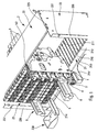
- the present invention as illustrated in Figures 1 to 9 implements several constituent elements, namely one or preferably several organ (s) of layout designated by the reference numeral 1 as well as one or more support structure (s) designated by reference numeral 2.
- the support structure 2 is in the form of a frame or a box open on its front side and its back side.
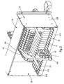
- the support structure has a geometric shape broadly parallelepiped. As for the fittings, they are housed in inside the load-bearing structure and can be extracted or put in place from the front side or the back side as we can see very clearly on Figure 2.
- the arrangement members are in the form of cassettes arranged vertically inside the support structure 2. In the following the description, the arrangement members will be designated by the term "Cassettes”. These cassettes have a general elongated configuration vertical. Their thickness is relatively small compared to their height and depth. In FIG.
- a cassette is partially engaged in the support structure 2: it can thus be seen that the height of the cassette corresponds substantially to the height of the support structure 2, its depth corresponds substantially to the depth of the support structure 2 while its thickness is very reduced, substantially on the order of 18.4 mm.
- Each cassette is held inside the support structure at the level of its upper edge and its lower edge. We will see below how cassettes are detachably locked and locked inside the support structure.
- Cassettes can be made of plastic or metal.
- the plastic is preferred, however.
- One-piece construction is possible and preferred.
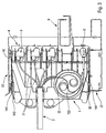
- Figures 5 and 6 show a bare cassette, that is to say devoid of any accessory (sockets, socket support, cables, cords).
- the cassette is here made in one piece from molded injected plastic.
- Figure 5 is a perspective view of one side of the cassette while FIG. 6 is a another perspective view on the other side of the cassette.
- the visible side in Figure 5 is the front side while the visible side in Figure 6 is the back side.
- Cassette 1 can be functionally divided into three zones, namely a front zone 11, an intermediate zone 12 and a rear zone 13. Each zone 11, 12 and 13 extends vertically substantially over the entire height of the cassette. Zone 11 defines the front part of the cassette.
- Zone 11 defines the front part of the cassette.
- the area before 11 defines or forms several housings 10 which are arranged vertically one above the other.
- the housings are open on the front of the cassette. These housings 10 are separated by sections of beam 103 which extend substantially horizontally forward. Each beam 103 defines the lower edge of the upper housing and the upper edge of the housing inferior. End beams, i.e. the upper end beam 103 and the lower end beam 103 ', respectively define only the upper edge of the lower housing and the lower edge of the upper housing. On the other hand, each beam 103 defines means of fixing 101 as well as a stabilizing flange 102. The fixing means defined by a beam 103 are associated with the upper housing 10 while the stabilizing flange 102 is associated with the lower housing. As for the beam upper 103 ', it forms only a stabilizing flange 102.
- each housing 10 is defined between two beams 103 and comprises fixing means 101 and a stabilizing flange 102.
- the fastening means 101 are located at the lower edge of the housing then that the stabilizing flange 102 is located on the upper edge of the housing.
- the front frontal area is essentially formed by a column of housings 10 each comprising own fixing means and a clean stabilizing flange.
- Each housing 10 is widely open towards the front but also open at the rear to communicate with the intermediate zone 12.
- This intermediate zone 12 is a development zone for connection cables such as electrical or optical cables.
- the area intermediate 12 can for example include a development zone of electrical cables 121 and a fiber development or coiling area optics 122.
- the area of development of the electric cables 121 is located above the coiling area for optical fibers 122.
- the three or four upper housings 10 can be intended for sockets electrical for example of the low current type while the lower housing 10 can be reserved for an optical type socket.
- the coiling area 122 can by example be in the form of a substantially cylindrical box with the interior of which the optical fiber can be arranged to conserve the radius curvature of the fiber without making marked folds. We can even use a cover to close the coiling box 122.
- the coiling box 122 includes an access ramp 1121 and an exit ramp 1122 which leads towards the lower housing 10. It can also be noted that this zone central or intermediate 12 is formed with a window 124 which makes connect the two side faces of the cassette. Indeed, we can clearly see in FIG. 6 that this window 124 opens onto the other face of the cassette.
- the rear zone 13 is a cable entry zone, and for this includes make an inlet duct 131 inside which a cord of cables can be housed and even fixed, for example using a collar.
- the cable cord, at the outlet of conduit 131 inside the cassette can then be divided into cables of electrical or optical power that will flourish or curl in the area central 12.
- This rear zone 13 also includes means for gripping 132 which may for example be in the form of holes for grip through which one can pass a finger of one hand and thus grasp firmly the cassette to push or pull it.
- gripping 132 may for example be in the form of holes for grip through which one can pass a finger of one hand and thus grasp firmly the cassette to push or pull it.
- part of the cord cables can also be passed through the window 124.
- the cassette also defines an upper edge and a lower edge. Each edge extends over all of zones 11, 12 and 13. These upper edges and lower extend substantially parallel. They define the maximum height of the cassette. This height is directly dependent on the number of housings formed by the cassette.
- the leading edge upper for example is formed by the upper face of the edge of the beam upper 103 '.
- the upper edge forms a rib 142 on at least part of its length. Preferably, the rib extends over practically the whole of the length of the top edge.
- This rib 142 therefore extends from the end beam 103 'and extends rearward to the level of the rear area 13.
- the rib 142 is formed by an elastically deformable tongue at from the intermediate zone 12. At the rear zone 13, the edge upper is only formed by this elastically deformable tongue 14.
- This elastically deformable tongue 14 also forms a grain of locking or blocking 141 which is positioned on the rib 142.
- This flange elastically deformable 14 therefore extends to the level of the rear zone 13 to form an actuating tab at which you can press using a finger of one hand to deform the flange 14.
- the rib 142 does not advantageously not extend to the level of this actuating tab 143.
- this actuating tab 143 functions means of unlocking to cancel or eliminate the function of unlocking provided by the locking grain 14.
- Locking means such as a locking grain as well as unlocking means such as a tongue 143 are provided on the edge upper part of the cassette but can also be provided on the lower edge of the cassette.
- the cassette is provided on these two upper edges and lower locking and unlocking means.
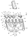
- FIGS 7 and 8 illustrate the cassette of Figures 5 and 6 with equipment accessories.
- the cassette is used according to the invention of arrangement means for connection means such as preferably low or optical current sockets.
- Each housing 10 is adapted to receive a weak 5 or optical 5 'socket which is inserted inside the housing 10 from the front of the cassette.
- support members are advantageously provided 4 which can be standard, and on which the 5, 5 'sockets are mounted, as it can be seen in Figure 7. Then, when the sockets 5 are mounted on the supports 4, the supports 4 are mounted in the housings 10 by inserting them from the front of the cassette.
- each support member 4 forms corresponding fixing means 41 intended to cooperate with the fastening means 101 of the housings 10.
- each support member 4 forms a blocking flange for engaging with the stabilizing flange 102 of the housing 10.
- the sockets are thus fixed in respective housing by through the supports. Direct fixing of sockets in the accommodation is also possible.
- the supports, respectively the sockets are removably received in their respective housings. It is also possible to remove the support from its housing from the front of the cassette without disassembling it.
- the fixing means 41 and 101 realize a reversible snap fastening, so that it is possible to remove the support of its housing.
- the latter For the reception of the 5 or 5 'socket in the support 4, the latter forms a reception compartment 45 in which the socket 5 can be inserted and fixedly held, for example by snap-fastening.
- the support member 4 On the front face, as can be seen in FIG. 8, the support member 4 forms a window 44 through which the socket 5 or 5 ′ is accessible, for example using an appropriate connector.
- the three dwellings upper 10 can be fitted with supports 4 receiving sockets weak 5, while only the lower housing 10 receives a support 4 equipped with a 5 'optical socket.
- the housing 10 located just above the housing receiving the 5 'optical socket can be fitted with any accessory such as for example a cable passage 6 also formed with associated fixing means 61 and a locking flange 62.
- the cable passage 6 can form two arms defining between them a closed space inside which you can pass cables for come and connect on the sockets through the window 44 of the supports 4. On the back of the cassette, one can send a cord 3 grouping together several cables, by electrical and optical examples.
- Figures 3 and 4 represent the cassette equipped with its supports 4 receiving the sockets 5 and 5 ', as well as the cable gland 6.
- the cables 31 and 32 of the cord cables 3 flourish or curl inside the cassette more particularly at the level of its central or intermediate zone 12. It is possible to in particular see that the electric cables 31 will come to connect on the sockets 5 received on the support members 4 fixed in the respective housings 10.
- the optical fiber 32 it coils inside the coiling area 122 to come out and reach the 5 'optical connector.
- FIGS. 1 and 2 we will now refer again to FIGS. 1 and 2 as well as to FIG. 9 to explain how the cassette cooperates with the structure of support 2.
- the support structure 2 is in the form of a box or a locker advantageously consisting of a bottom plate 21 and a plate upper 22 connected together by two spacer elements 23.
- the plates 21 and 22 are connected to the lateral elements 23 by nesting and locking systems only, so that organs fasteners such as screws or rivets are not required. So the mounting a support structure 2 can be done manually or automated way without the help of specific tools such as screwdrivers or rift recipients.
- the two lateral elements 23 can be strictly identical or at least symmetrical according to a mirror symmetry.
- Each side element 23 forms a basic panel 230 pierced with several lights or notches used for the fixing plates 21 and 22 as well as fixing accessories such as a cable grommet general 238.
- the lateral elements 23 also form a return 236 which is also pierced with windows 237 used for fixing the structure of support 2 on vertical rails forming a load-bearing bay.
- the two returns 236 extend in the same plane of so that they can be applied on the rails of the carrier bay. It is then easy by means of screws or bolts to fix the support structure on the rack carrier.
- the lower plate 21 and the upper plate 22 can be of completely identical structure, but preferably the lower plate 21 is differentiates from the upper plate 22 by the presence of a frontal strip 213 which can be used as a base for fixing accessories such as cable grommets 214, as can be seen in FIG. 1.
- the frontal strip 213 can also be fitted with other cable glands 214 ', as can be see also in Figure 1.
- the two plates 21 and 22 have a common configuration which consists of a holding plate 210, 220 respectively for the support plates 21, 22.
- Each plate 210, 220 is a support and holding element for cassettes 1. Both plates 210, 220 face each other inside the support structure 2.
- the plate 210 constitutes lower support and holding means while the plate 220 constitutes superior support and holding means.
- Each turntable is formed with means for guiding in translation which appear here under the form of slots aligned parallel 212 and 222. These slots 212 and 222 extend substantially over the entire width of the plate so as to lead to each side of the plate.
- Each slot also forms a blocking window 211 which is advantageously located near the face rear of the support structure 2, as can be seen in FIGS. 1 and 2.
- the two plates 210 and 220 can be formed with such windows 211, 221 or alternatively, only one of the plates can have such windows.
- a slot 212 in the plate lower 210 extends in the same vertical plane as a slot 221 of the plate upper 220.
- the slots can thus be associated in pairs located in adjacent vertical planes in parallel.
- each cassette 1 is held inside the supporting structure 2 by engaging with the lower plate 210 and the plate upper 220.
- each cassette 1 comprises one or two rib (s) 142 which extend at one or both edge (s) top and bottom of the cassette.
- these ribs 142 are provided with a locking grain 141.
- each cassette 1 can be engaged in the support structure 2 so as to insert the one or more rib (s) 142 in a pair of slots 212, 222 formed by the plates 210, 220. As soon as the ribs 142 are partially engaged in the slots, the cassette is guided in translation and can thus be slid inside the support structure 2 between the two plates 210, 220.
- the cassette 1 can be thus moved until its grain 141 comes to click into a window respectively 211, 221. This is possible since the grain 141 is placed on the elastically deformable flange 14.
- the tab (s) 14 are elastically deformed up to that their respective grains are housed inside the windows 211, 221.
- the cassette is practically entirely inscribed inside the volume constituted by the support structure 2, as can be seen in Figures 1 and 2.
- a series of cassettes is already inserted at the inside of structure 2 so that the front faces of each cassette are located substantially in the same plane. So the plugs all form together a regular and uniform table formed of independent columns formed by each cassette.
- the structure support 2 can be completely filled with cassettes 1 arranged side by side vertically with a pitch corresponding to the pitch of the slots 212, 222.
- a complete table consisting of strong sockets, sockets weak, and possibly a free row which is advantageously provided with a accessory such as a cable gland 6 or closed with a cover.
- the different cassettes are pre-assembled in the factory or in workshop, i.e. the connector supports as well as the connectors are pre-installed in the housing and even pre-wired with a length of cables sufficient to then be able to extend the cable to the workstation at install.
- the operator responsible for mounting the distributor no longer has that to put the cassettes in place in the support structure 2 which is very easy to assemble since it does not require the use of specific tools.
- the ground recovery on the connectors of the prior art is done by means of a horizontal rectilinear bus fitted with flexible elements which come into contact with the connector shell.
- This bus also has lug-type connection elements for connecting by means of flexible straps the strip in question at the upper and lower stripes, then at the line General.
- the vertical cassette is equipped with pins individual earth connection 152 electrically connecting the connectors, as we can see it on figure 7.
- Each pin is in contact in its lower part with the metallic or metallized casing of the connector (socket) and in its part top with the connector pin located just above, and so on depending on the number of connectors up to a general recovery pin 151 which is located in the upper position of the cassette and which comes to touch by means a flexible element the upper support 22 of the frame 2 which is conductive (for metallic or metallized example) and which connects the 24 cassettes to general earth at by means of a pod.
- the spirit of the present invention resides in the vertical configuration while very original which allows to depart from the standard 19 inch dimension of the load-bearing bay.
- the entire organization or arrangement of connectors is carried out so vertically and no longer horizontally as was the case with plates or headbands of the prior art.
- a workshop assembly is possible, which significantly reduces installation costs.
- Each socket is received individually in a respective housing which is provided with own fixing means, of the removable snap-on type; the sockets are inserted into their respective housings from the front of the cassette without having to dismantle it.
- it is possible to reconfigure the arrangement of the sockets on the cassette (s) without having to remove the cassette from its support structure and without demonstrating the cassette, and this from the front visible from the cassette. It is not necessary to use any tools to install and remove the sockets from their associated housings.
Landscapes
- Physics & Mathematics (AREA)
- General Physics & Mathematics (AREA)
- Optics & Photonics (AREA)
- Light Guides In General And Applications Therefor (AREA)
Applications Claiming Priority (2)
| Application Number | Priority Date | Filing Date | Title |
|---|---|---|---|
| FR0300386 | 2003-01-15 | ||
| FR0300386A FR2849965B1 (fr) | 2003-01-15 | 2003-01-15 | Organe d'agencement de moyens de connexion, dispositif de montage de moyens de connexion et baie porteuse. |
Publications (1)
| Publication Number | Publication Date |
|---|---|
| EP1443603A1 true EP1443603A1 (de) | 2004-08-04 |
Family
ID=32524923
Family Applications (1)
| Application Number | Title | Priority Date | Filing Date |
|---|---|---|---|
| EP04290093A Withdrawn EP1443603A1 (de) | 2003-01-15 | 2004-01-14 | Anordnungselement für Anschlussmittel, Anbauvorrichtung von Anschlussmitteln und Baugruppenträger |
Country Status (2)
| Country | Link |
|---|---|
| EP (1) | EP1443603A1 (de) |
| FR (1) | FR2849965B1 (de) |
Cited By (1)
| Publication number | Priority date | Publication date | Assignee | Title |
|---|---|---|---|---|
| WO2007051611A3 (de) * | 2005-11-07 | 2007-08-23 | Adc Gmbh | Verfahren und vorrichtung zum koppeln von lichtwellenleitern |
Citations (7)
| Publication number | Priority date | Publication date | Assignee | Title |
|---|---|---|---|---|
| FR931803A (fr) * | 1946-08-06 | 1948-03-04 | Radioelectriques Lab | Dispositif de connexion pour circuits électriques contenus dans des tiroirs d'un meuble |
| FR2480512A1 (fr) * | 1980-04-15 | 1981-10-16 | Connei Spa | Dispositif connecteur a fiches multiples, compose d'elements individuels, en particulier pour connecteurs electriques |
| US5413494A (en) * | 1992-10-05 | 1995-05-09 | Adc Telecommunications, Inc. | Jack module assembly |
| US5613030A (en) * | 1995-05-15 | 1997-03-18 | The Whitaker Corporation | High density fiber optic interconnection enclosure |
| EP1005235A2 (de) * | 1998-11-25 | 2000-05-31 | Reichle & De-Massari AG | Vorrichtung zum Befestigen moduler Mehrfach-Anchlussleisten an parallelen Trägerelementen eines Verteilergestells einer Telefonzentrale o. dgl. |
| US6241562B1 (en) * | 1999-06-22 | 2001-06-05 | Avaya Technology Corp. | Digital cross connect/interconnect module |
| US20020151221A1 (en) * | 2001-04-13 | 2002-10-17 | Johnsen David J. | DSX jack including sliding rear connector |
-
2003
- 2003-01-15 FR FR0300386A patent/FR2849965B1/fr not_active Expired - Fee Related
-
2004
- 2004-01-14 EP EP04290093A patent/EP1443603A1/de not_active Withdrawn
Patent Citations (7)
| Publication number | Priority date | Publication date | Assignee | Title |
|---|---|---|---|---|
| FR931803A (fr) * | 1946-08-06 | 1948-03-04 | Radioelectriques Lab | Dispositif de connexion pour circuits électriques contenus dans des tiroirs d'un meuble |
| FR2480512A1 (fr) * | 1980-04-15 | 1981-10-16 | Connei Spa | Dispositif connecteur a fiches multiples, compose d'elements individuels, en particulier pour connecteurs electriques |
| US5413494A (en) * | 1992-10-05 | 1995-05-09 | Adc Telecommunications, Inc. | Jack module assembly |
| US5613030A (en) * | 1995-05-15 | 1997-03-18 | The Whitaker Corporation | High density fiber optic interconnection enclosure |
| EP1005235A2 (de) * | 1998-11-25 | 2000-05-31 | Reichle & De-Massari AG | Vorrichtung zum Befestigen moduler Mehrfach-Anchlussleisten an parallelen Trägerelementen eines Verteilergestells einer Telefonzentrale o. dgl. |
| US6241562B1 (en) * | 1999-06-22 | 2001-06-05 | Avaya Technology Corp. | Digital cross connect/interconnect module |
| US20020151221A1 (en) * | 2001-04-13 | 2002-10-17 | Johnsen David J. | DSX jack including sliding rear connector |
Cited By (3)
| Publication number | Priority date | Publication date | Assignee | Title |
|---|---|---|---|---|
| WO2007051611A3 (de) * | 2005-11-07 | 2007-08-23 | Adc Gmbh | Verfahren und vorrichtung zum koppeln von lichtwellenleitern |
| US8019191B2 (en) | 2005-11-07 | 2011-09-13 | Adc Gmbh | Method and device for coupling optical waveguides |
| DE102005052882B4 (de) * | 2005-11-07 | 2011-12-01 | Adc Gmbh | Verfahren und Vorrichtung zum Koppeln von Lichtwellenleitern |
Also Published As
| Publication number | Publication date |
|---|---|
| FR2849965B1 (fr) | 2016-04-01 |
| FR2849965A1 (fr) | 2004-07-16 |
Similar Documents
| Publication | Publication Date | Title |
|---|---|---|
| CA2086373C (fr) | Dispositif de soutien et de guidage de cables de transmission de signaux electriques ou lumineux | |
| FR2531576A1 (fr) | Bati de raccordement et d'interface opto-electronique | |
| EP1018191B1 (de) | Schwachstromstecker mit organisations-rückverschlusskappe | |
| EP0101970B1 (de) | Anschlussstück eines faseroptischen Kabels | |
| EP0116480A1 (de) | Gehäuse zum Verbinden und Mischen optischer Fasern | |
| CN102884465A (zh) | 用于光学纤维罩壳的可移除纤维管理器件,以及相关的组件和方法 | |
| WO2014096674A1 (fr) | Boite électrique pour appareillage électrique | |
| EP3138169B1 (de) | Verbinder für elektrische vorrichtung in einer eingelassenen box | |
| EP3605749B9 (de) | Halterung für ein elektrisches gerät und entsprechendes elektrisches gerät | |
| EP0859526A1 (de) | Modulare Verteilerleiste für ein Datennetz | |
| EP2775334B1 (de) | Vorrichtung, die eine Vielzahl von Klemmenanschlusskästen und/oder Lagerkästen für Kabel oder Kabelfasern umfasst | |
| EP1249908B1 (de) | Befestigungsvorrichtung für einen elektrischen Verbindungsstecker | |
| EP0578576B1 (de) | Elektrische Anschlussklemme | |
| EP1443603A1 (de) | Anordnungselement für Anschlussmittel, Anbauvorrichtung von Anschlussmitteln und Baugruppenträger | |
| EP2456032A1 (de) | Vorrichtung zum Verstauen von Stromkabeln | |
| EP2068186A1 (de) | Optischer Stecker für Telekommunikationsnetz | |
| FR2698729A1 (fr) | Dispositif de connexion électrique d'une pluralité de câbles. | |
| FR2786940A1 (fr) | Appareil electrique destine a etre mis en place dans un support | |
| CA2138239A1 (fr) | Socle multiple pour prise de courant | |
| EP2805524B1 (de) | Trägervorrichtung zur verdrahtung einer schalttafel in einem schaltschrank | |
| FR2813715A1 (fr) | Dispositif de precablage dans une installation de cablage et procede de mise en oeuvre | |
| EP1624529B1 (de) | Verbinderbefestigungsanordnung mit einem Verbindungselement zum Verbinden von zwei nebeneinander angeordneten Verbinderbefestigungen | |
| EP0743703A1 (de) | Elektrische Steckdose mit stirnseitigen Abschluss und Montagewerkzeug | |
| FR2687509A1 (fr) | Boitier support de prises electriques normalisees et element de precablage incluant un tel boitier. | |
| FR2765062A1 (fr) | Repartiteur de reseau electrique ou optique et tete de cable destinee a etre montee dans un tel repartiteur |
Legal Events
| Date | Code | Title | Description |
|---|---|---|---|
| PUAI | Public reference made under article 153(3) epc to a published international application that has entered the european phase |
Free format text: ORIGINAL CODE: 0009012 |
|
| AK | Designated contracting states |
Kind code of ref document: A1 Designated state(s): AT BE BG CH CY CZ DE DK EE ES FI FR GB GR HU IE IT LI LU MC NL PT RO SE SI SK TR |
|
| AX | Request for extension of the european patent |
Extension state: AL HR LT LV MK |
|
| 17P | Request for examination filed |
Effective date: 20050203 |
|
| AKX | Designation fees paid |
Designated state(s): BE ES FR GB IT |
|
| REG | Reference to a national code |
Ref country code: DE Ref legal event code: 8566 |
|
| 17Q | First examination report despatched |
Effective date: 20050531 |
|
| RBV | Designated contracting states (corrected) |
Designated state(s): BE ES FR GB IT |
|
| 17Q | First examination report despatched |
Effective date: 20050531 |
|
| STAA | Information on the status of an ep patent application or granted ep patent |
Free format text: STATUS: THE APPLICATION IS DEEMED TO BE WITHDRAWN |
|
| 18D | Application deemed to be withdrawn |
Effective date: 20101229 |