EP1443747A2 - Procédé d'impression d'une image à partir d'une image binaire en demi-teintes en utilisant plusieurs valeurs d'exposition - Google Patents
Procédé d'impression d'une image à partir d'une image binaire en demi-teintes en utilisant plusieurs valeurs d'exposition Download PDFInfo
- Publication number
- EP1443747A2 EP1443747A2 EP04075157A EP04075157A EP1443747A2 EP 1443747 A2 EP1443747 A2 EP 1443747A2 EP 04075157 A EP04075157 A EP 04075157A EP 04075157 A EP04075157 A EP 04075157A EP 1443747 A2 EP1443747 A2 EP 1443747A2
- Authority
- EP
- European Patent Office
- Prior art keywords
- dot
- halftone
- pixels
- feature
- image
- Prior art date
- Legal status (The legal status is an assumption and is not a legal conclusion. Google has not performed a legal analysis and makes no representation as to the accuracy of the status listed.)
- Withdrawn
Links
Images



Classifications
-
- H—ELECTRICITY
- H04—ELECTRIC COMMUNICATION TECHNIQUE
- H04N—PICTORIAL COMMUNICATION, e.g. TELEVISION
- H04N1/00—Scanning, transmission or reproduction of documents or the like, e.g. facsimile transmission; Details thereof
- H04N1/40—Picture signal circuits
- H04N1/40081—Soft dot halftoning, i.e. producing halftone dots with gradual edges
-
- H—ELECTRICITY
- H04—ELECTRIC COMMUNICATION TECHNIQUE
- H04N—PICTORIAL COMMUNICATION, e.g. TELEVISION
- H04N1/00—Scanning, transmission or reproduction of documents or the like, e.g. facsimile transmission; Details thereof
- H04N1/40—Picture signal circuits
- H04N1/407—Control or modification of tonal gradation or of extreme levels, e.g. background level
Definitions
- This invention generally relates to a method for printing halftone images and more particularly relates to a method for modifying halftone images at higher resolution by adjusting dot-gain using multiple exposures.
- the present invention is designed to filter an image then quantized the images with a set of discrete "n" levels.
- the job is sent to a second RIP that applies a second dot-gain curve for generating the plate used in the press run.
- the first and second RIPs may be the same but are typically separate and may be located apart from each other.
- the first and second RIPs are preferably the same type and version such that the halftone dots created and algorithms used by each device are an exact match, however, many times the two RIPs do not match exactly. Sometimes incorrect dot-gain correction files are used. Sometimes the artwork is changed in-between creating the proof and the plates and the press run no longer matches the approved proof.
- Another disadvantage in the current system is that an error in the creation of the bitmaps for printing is not known until the plates are loaded onto the press and the press run is started. For a press capable of over 1,000 impressions per hour considerable amount of production is lost if the plates are found to be corrupt and need to be remade.
- Dot-gain is a known phenomenon attributable to ink spread, ink absorption by the print media, and optical effects between the ink and the paper.
- the dot-gain varies with the size and shape of the halftone dots, the printing device, the inks, and the paper used, etc.
- halftone dots in a color separation are composed of micro-pixels that give the halftone dot its shape and size.
- Dot-gain for a digital proof corresponds to increasing dot size by adding micro-pixels.
- Dot-loss for a digital proof corresponds to decreasing dot size by eliminating micro-pixels.
- Dot-gain correction consists of adding and subtracting gain to match the response at different percent dot inputs.
- the exposure for each color plane is adjusted to match the solid area density.
- the dot-gain for each color plane is adjusted to achieve a dot-gain match at different halftone tint levels.
- the dot-gain curves and density levels may be fine-tuned to achieve either a good neutral match in the three-color overprints or a color match of the flesh tones. For some work other memory colors such as green grass or light blue sky may be matched as the critical color.
- the dot-gain curves may be further adjusted to deliver better performance in the highlight, or shadow areas.
- the proofer setup is used to simulate the press such that the pressman may then use the proofs to setup the press to achieve the customer's intent. Every job going through the proofer will be adjusted with a setup. There may be different setups for each press or press type. There may also be different setups for different customers using the same proofer. Finally, there may also be standard setups that are used to simulate jobs across many different presses.
- the same job is typically ripped again when going to press. This time the RIP is programmed to generate 50% area coverage on plate for the 50% color input. The press is then run to deliver a fixed amount of gain at the 50% input level. Dot-gain is due to the smearing of the ink from the plate to a blanket, the smearing of ink from the blanket to the job paper, and the optical gain of the ink on top of the paper.
- the control is usually split between the plate-making device delivering 50% area coverage for a 50% input, and the press delivering 50% plus its intrinsic dot-gain. Typical dot-gain levels for a web-fed offset press are 15% to 25% at the 50% input level.
- bitmaps used to create the plate will not contain enough gain to make the proof. Proofs made from these bitmaps will be washed out and the contrast will be significantly reduced. Colors will also shift, as the gain in each color will be proportional to the dot area coverage.
- Inkjet printing devices are also sometimes used to make a proof. These devices typically image from 300 dpi to 1440 dpi writing resolutions using multiple cyan, magenta, yellow, and sometimes black inks.
- software such as "Best Screen Proof” available from Best Gmbh, or Black Magic available from Serendipity Software Pty. Ltd., may be used to simulate the printing of a halftone screen. This software attempts to measure the halftone screen and adjust the printed output to achieve a close color match to a given target. Resolution of the inkjet devices does not allow for a good match of the halftone dot structure. The color match developed does simulate the tone-scale or dot-gain correction, but only through the driving of the overlapping colors on the proof.
- the quality of the halftone in the printed proof is significantly compromised. Dots in the highlight and shadow areas are destroyed in trying to match the overall density level in these systems. This is because the inkjet output drops are too large. Therefore, one inkjet drop is used to replace many halftone dots in the highlight or bright areas, while one inkjet hole is used to replace many halftone holes in the shadows.
- An inkjet printer with a 3 pL drop size will produce a dot with a diameter of about 25 um covering an area of 625 um 2 . This may vary depending upon the spread into the paper.
- a single inkjet drop represents a 2.18% change in area within a 150-line screen halftone.
- the Best Screen Proof, and Black Magic software use additional inks to image multi-level colorants. Typically a light cyan and light magenta ink are added to the cyan, magenta, yellow, and black primaries to achieve finer control of the tone-scale. While this creates a proof with a close visual color match, the structure of the halftone dots within the image is seriously degraded.
- the conventional proofing solution using the a direct digital color halftone proofer, is to RIP the file for proofing separate from ripping the file for printing, adding dot-gain to the proofing file as part of the ripping process.
- U.S. Patent No. 5,255,085 discloses a method to adjust the tone reproduction curve of a press or output printer. This method creates a target from the press or desired output proof, benchmarks the characteristics of the proofing device, and generates a lookup table to adjust the dot-gain of the original file to achieve the aim on the proofing device.
- 5,293,539 adds adaptive process values to interpolate between measured benchmark and aim data sets to calibrate the dot-gain tone-scale curve at other screen rulings, screen angles, and dot shapes. Utilizing these techniques to modify the dot-gain curves and hence the tone-scale curves of the proofing device increases the chances for error.
- the input file and its subsequent components must be available for both RIPs.
- the same versions of each file and components must be specified.
- the same fonts must be available for both RIPs.
- the correct dot-gain curve must be specified at both RIPs. The chances for error to occur increase with each ripping operation, especially when the RIPs are located at separate sites.
- Current direct digital color halftone proofers implement dot-gain by modifying the code values being printed through a curve prior to converting the code values into the halftone bitmap with the raster image processor (RIP).
- the dot-gain is only applied to the continuous tone image data and not the line work or text.
- the dot-gain may be adjusted for each of the primary colors cyan, magenta, yellow, and black.
- a dot-gain curve may also be specified for spot colors orange, green, red, blue, white, and metallic.
- a dot-gain curve may also be specified for a recipe color that is imaged using a single bitmap in combination of two or more standard colors at unique exposure levels.
- a dot-gain curve may also be specified for each colorant within a recipe color. In this last case more than one bitmap is used, however the halftone dots are at the same screen ruling, screen angle, and phase, such that each halftone dot in each color substantially overlap.
- a benchmark proof is then run and measured. It is possible to measure 30%, 60%, and 79% cyan dot area coverage at the 25%, 50%, and 75% input levels. Dot area is calculated based on measured density using the equation defined by Murray-Davies. The Murray-Davies equation is defined in ANSI/CGATS, 4-1993, 1993, p. 7. A dot-gain adjustment curve is then created to add the correct amount to cyan to achieve the target values at the target inputs.
- Perup Oskofot has disclosed at Drupa 2000 a software program, which operates on high resolution scans from their scanners.
- the program takes a binary high-resolution scan of a halftone film and de-screens it to a lower resolution continuous tone image.
- the scan resolution is 2400 dpi.
- the resulting continuous tone image may be 8-bits per pixel at 300 dpi resolution.
- a dot-gain curve is then applied to the de-screened image.
- the adjusted image is then reripped to a bitmap image at 2400 dpi.
- One problem with this method is that it requires a reripping step. Plus it must be known what the original halftone screen shape, screen ruling, and screen angle were in order to faithfully reproduce it with the reripping step.
- some customers have halftone films, which they would like to use in their digital workflow. These customers scan the film at a high resolution, 100 pixels/mm, and quantize each pixel to a binary value. Because the dot-gain is built into the film, there is no method other than de-screening the bitmap file, adding dot-gain, and reripping the file, to calibrate the output print. If the original film was made using an optical technique then the dot shape, screen ruling, and screen angle may not be an exact match to a digital RIP. De-screening and re-screening the high-resolution scan may not faithfully reproduce the original screens.
- U.S. Patent No. 5,250,934 discloses a method of shifting and adding a bitmap image with itself to thin the image displayed.
- U.S. Patent No. 5,250,934 also discloses a method of setting a bit to an intermediate level if it is diagonally between two active bits using shifting, logical and, and a logical or operation.
- U.S. Patent No. 5,483,351 discloses using a 4x4 input to a lookup table to determine how to operate on the central 2x2 pixels to implement half bit or full bit dilation and erosion in U.S. Patent No. 5,483,351.
- U.S. Patent No. 5,483,351 has the advantage of knowing some of the surrounding pixels in deciding how to dilate or erode the pixels in the center.
- U.S. Patent No. 5,258,854 teaches how to resize bitmap images in small amounts less than one full bit in size.
- U.S. Patent No. 5,680,485 discloses logically combining two morphological filter pairs and an original image to create an output image.
- the morphological filters described are erosion filters, one of which has less erosion than desired and the other having more erosion than desired. Logically combining combinations of the original image with the two eroded images provides for a method of obtaining an intermediate result.
- U.S. Patent No. 5,208,871 describes a method of resizing an input bitmap.
- U.S. Patent No. 5,208,871 simulates a scan of an output image from an input bitmap such that the scan resolution is different from the input bitmap.
- Error diffusion is utilized to quantize the output bitmap into the desired output bit resolution. This example uses error diffusion to spread out the error in the quantization of a multilevel pixel into a reduced number of output states.
- U.S. Patent No. 6,115,140 uses a de-screened version of an original image, and dilated and eroded versions of the original image to select a combination of the original, dilated, and eroded images to effect a dot-gain or tone-scale change in an input bitmap image.
- U.S. Patent No. 6,115,140, Figure 5B shows an original halftone image input into block HI along with an eroded version (HE), and two dilated versions (HD1 and HD2). Then a weight based on de-screened versions of the original halftone (CO), the color corrected original (CI), the eroded original (CE), and the two dilated originals (CD1 and CD2) is calculated.
- the de-screened images are used to select which of the four halftone images, HI, HE, HD1, and HD2, are transferred into H1 and H2.
- the weighting function is then used to merge bitmap versions of H1 and H2 together into the tone-scaled output bitmap (HO). How to de-screen is not disclosed, nor exactly how to calculate which bit of H1 and H2 is used to drive the output bit HO. The need to use error diffusion to distribute the error in selecting between H1 and H2 is not mentioned.
- U.S. Patent No. 6,115,140 references teach how to perform de-screening.
- U.S. Patent No. 4,630,125 performs de-screening by comparing the number of white and dark pixels within a specified area.
- U.S. Patent No. 4,630,125 also states "A partial solution known in the art is to spatially filter the halftone image with a low pass filter.”
- U.S. Patent No. 4,630,125 teaches that the spatial filter method is not exact as it tends to blur the original image.
- the invention relates to a method for printing an image from a halftone binary bitmap having pixels comprising the steps of first, creating a feature location identification filter for a halftone binary bitmap image. Next, the feature location identification filter is used to map pixel identifications. A location specific exposure is then assigned to the mapped pixel identifications. Media is exposed using the location specific exposures to create an image on a printer.
- the feature location identification filter is preferably a filter created by the steps: assigning pixels to address bits of a lookup table; forming a lookup table by creating a set of all possible addresses for the pixels and mapping the set of addresses to a feature of a halftone dot forming mapped address bits; and then assigning a value to each feature of a halftone dot using the mapped address bits to create an output.
- an image 10 can be printed from a halftone binary bitmap 12 having pixels 14.
- the halftone binary bitmap 12 can be an image, such as a digital image, line work or text.
- the digital images can be color, or black and white images.
- the images may be continuos-tone, multi-level, or binary.
- the halftone binary bitmap 12 can be output from a raster image processor (RIP). It can be a customer plane, such as cyan, magenta, yellow and black. It can consist of customer artwork which is composed of pages using software such as Quark Express or Adobe InDesign. Every halftone binary bitmap 12 will have a halftone screen ruling and angle.
- the binary data will be at the writing resolution of the output printer 24.
- the steps of the method include first creating a feature location identification filter 16 for the halftone binary bitmap 12.
- the purpose of this filter is to map each pixel with an identifier to classify where the pixel is with respect to a halftone dot within the halftone binary bitmap.
- Many pixels 14 will be used to compose each halftone dot. For example pixels may be outside, inside, or on the edge of the area of a halftone dot.
- Figure 2 shows an example halftone binary bitmap 12 composed of pixels 14 creating a halftone dots 26a and 26b.
- Pixels 14a, 14b and 14c represent pixels on the edge of halftone dot 26a.
- Pixels 14d and 14e are in the center of halftone dot 26b.
- Pixels 14f and 14g are outside the area of the halftone dots 26a and 26b. These locations are called half tone dot features.
- Each pixel has a multilevel value for identifying each significant feature.
- the feature location identification filter is used to map pixel identifications 18, one or more features, for each half tone dot of the halftone bitmap.
- the pixel identifications 18 are represented by different pixels features 18a-18g, such as the pixel edge, the pixel center corresponding to the position the pixel is in relative to the halftone dots 26a and 26b.
- a location specific exposure 20 is assigned to the mapped pixel identifications.
- Figure 4 shows the corresponding locations specific exposures for each pixel identification shown in Figure 3.
- "Off" is shown in the squares indicated as element 20f and 20g. Off is also outside the dot.
- the edge exposure level is shown in the squares indicated as elements 20a, 20b, and 20c.
- the inside of the dot exposure level is indicated as 20d and 20e.
- the single dot exposure level is not shown but would consist of a single "on" pixel surrounded by "off' pixels.
- printers which can be used in this invention are contemplated to be laser printers, such as a multilevel printer laser printer capable of printing at a dpi between 1400 and 4000, preferably between 1800 and 4000 dpi. It is contemplated that a Kodak approval XP printer could be used with the modification to pulse width modulate the lasers up to sixteen levels for each pixel at 2540 dpi using colors cyan, magenta, yellow and black. It is contemplated that the individual exposures can be set for each of the sixteen levels for each color plane. This means, the exposures can be flexibly changed with this system.
- Figure 5 shows yet another embodiment of the invention.
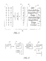
- the feature location identification filter 16 has all possible inputs 30 for three pixels to the filter. All possible outcomes 32 are shown as the result of the filtering of the inputs. These outcomes 32 may be classified as features 18.
- the features 18 in this embodiment can be "off" 33; outside edge 34; single pixel 35; edge of halftone dot 36; outside edge of halftone dot 37; single hole outside of halftone dot 38; edge of halftone dot 39; and center of halftone dot 40.
- Figure 6 reveals that the method uses a feature location identification filter 16 can be created by the steps involving:
- Figure 7 shows how a 3 x 3 array of pixels can be used to create a nine bit address, using pixels 54, 56, 58, 60, 62, 64, 68, 70, 72 are shown.
- a five bit address could also be created from this 3 x 3 array by using pixel 56, 60, 62, 64, and 70 to identify half tone dot features along the axis of the selected five pixels.
- the subsequently created lookup table is smaller than the nine bit table.
- a 5 x 5 array of pixels can also be used to identify more features of a halftone dot, such as pixels which are at the edge versus pixels in the center of a half tone dot.
- the feature location identification filter can be a lookup table created by the steps: creating a set of all possible addresses for the pixels, and mapping the set of address to a feature of a halftone dot forming mapped pixel address bits, wherein addresses for pixels are composed of adjacent pixels, and the lookup table is adapted to provide mapped pixel identifications.
- the filter can be composed of pixels in one direction, or in two directions.
- the lookup table is a table comprising between 3 and 25 bits.
- the assigned location specific exposure can be greater for an edge of the halftone dot than a center of the halftone dot.
- the assigned location specific exposure can be greater for an edge of the halftone dot than a center of the halftone dot.
- Location specific exposures can be set by calibrating each of the halftone features to the screen ruling and angle of the original binary hafltone bitmap.
- the invention is designed to image the bitmap such that the image 10 is calibrated to another printing device.
- This device may be a press, either sheet fed or web fed. It may also be another printer.
- the location specific exposure is set by first, for each feature 18 starting with the smallest, compose a target 80.
- the target is built by first creating a tile 82a, the same size as the filter 16 containing only one feature 18a. The step is repeated with additional tiles and the same feature, 82b and 18b, tile 82c and features 18c, tile 82d and feature 18d, tile 82e and feature 18e and so on until the target is filled with tiles.
- a preferred embodiment contemplates using a target having a 1 ⁇ 2 inch by 1 ⁇ 2 inch area. This target building is shown in Figure 8.
- each target is printed at different exposure levels forming a calibration output.
- the calibration output is measured for density at each different exposure level forming a density measurement for each different exposure level.
- the density measurements are converted to a dot-gain for each different exposure level.
- Dot-gain is measured using the Murray-Davies equation.
- the percent dot of the target is equal to the number of pixels in the tile divided by the size of the tile in pixels. Then subtracting the measured percent dot from the percent dot of the target, then the dot-gain is determined.
- the halftone bitmap has a screen ruling and an angle that the bitmap was created too. When the feature in the current target appears in the halftone bitmap it will be at the screen ruling. Therefore, the percent dot when the feature appears is equal to the size of the feature multiplied by the screen ruling squared.
- the exposure is set to achieve the dot-gain desired at this equivalent percent halftone dot to match the other printing device.
- This calibration process is performed on the smallest feature first, in the preferred embodiment, then using the exposure for the smallest feature, then this calibration process is repeated for each subsequently larger feature.
- the target is composed of a feature within an area to be filtered by the feature location identification filter.
- the location specific exposure for a single dot exposure can be adjusted to be greater than the average exposure of dots in the halftone binary bit map.
- the method of the invention contemplates performing this process separately in each color plane in a color printer.
Landscapes
- Engineering & Computer Science (AREA)
- Multimedia (AREA)
- Signal Processing (AREA)
- Facsimile Image Signal Circuits (AREA)
- Image Processing (AREA)
- Color, Gradation (AREA)
- Preparing Plates And Mask In Photomechanical Process (AREA)
Applications Claiming Priority (2)
| Application Number | Priority Date | Filing Date | Title |
|---|---|---|---|
| US10/355,600 US6893105B2 (en) | 2003-01-31 | 2003-01-31 | Method for printing an image from a halftone binary bitmap using multiple exposures |
| US355600 | 2003-01-31 |
Publications (2)
| Publication Number | Publication Date |
|---|---|
| EP1443747A2 true EP1443747A2 (fr) | 2004-08-04 |
| EP1443747A3 EP1443747A3 (fr) | 2009-03-25 |
Family
ID=32655582
Family Applications (1)
| Application Number | Title | Priority Date | Filing Date |
|---|---|---|---|
| EP04075157A Withdrawn EP1443747A3 (fr) | 2003-01-31 | 2004-01-19 | Procédé d'impression d'une image à partir d'une image binaire en demi-teintes en utilisant plusieurs valeurs d'exposition |
Country Status (3)
| Country | Link |
|---|---|
| US (1) | US6893105B2 (fr) |
| EP (1) | EP1443747A3 (fr) |
| JP (1) | JP2004236309A (fr) |
Families Citing this family (5)
| Publication number | Priority date | Publication date | Assignee | Title |
|---|---|---|---|---|
| US7545997B2 (en) * | 2004-09-10 | 2009-06-09 | Xerox Corporation | Simulated high resolution using binary sub-sampling |
| JP5395653B2 (ja) * | 2009-12-28 | 2014-01-22 | 富士フイルム株式会社 | 検版システム、検版方法及びプログラム |
| JP5395654B2 (ja) * | 2009-12-28 | 2014-01-22 | 富士フイルム株式会社 | ページ記述データ生成方法、プログラム及びデータフォーマット |
| US8842938B2 (en) * | 2012-06-27 | 2014-09-23 | Xerox Corporation | Method and system for performing resolution expansion with high quality edge enhancement |
| US10574859B2 (en) * | 2014-04-02 | 2020-02-25 | Airdye Intellectual Property Llc | Color management system for application of color to substrates |
Family Cites Families (17)
| Publication number | Priority date | Publication date | Assignee | Title |
|---|---|---|---|---|
| US4630125A (en) * | 1983-06-01 | 1986-12-16 | Xerox Corporation | Unscreening of stored digital halftone images |
| US5164742A (en) * | 1989-12-18 | 1992-11-17 | Eastman Kodak Company | Thermal printer |
| US5208871A (en) * | 1990-10-19 | 1993-05-04 | Xerox Corporation | Pixel quantization with adaptive error diffusion |
| US5250934A (en) * | 1990-12-31 | 1993-10-05 | Xerox Corporation | Method and apparatus for thinning printed images |
| US5293539A (en) * | 1991-10-25 | 1994-03-08 | Eastman Kodak Company | Method and apparatus for calibrating tone reproduction in a proofing system |
| US5255085A (en) * | 1991-10-25 | 1993-10-19 | Eastman Kodak Company | Adaptive technique for providing accurate tone reproduction control in an imaging system |
| US5258854A (en) * | 1991-12-06 | 1993-11-02 | Xerox Corporation | Converting between write-white, write-black and neutral bitmaps |
| US5483351A (en) * | 1992-09-25 | 1996-01-09 | Xerox Corporation | Dilation of images without resolution conversion to compensate for printer characteristics |
| US5440407A (en) * | 1994-03-11 | 1995-08-08 | Hewlett-Packard Company | Pixel correction and smoothing method |
| JPH07264402A (ja) * | 1994-03-18 | 1995-10-13 | Dainippon Screen Mfg Co Ltd | 印刷版画像の作成方法 |
| US5680485A (en) * | 1994-12-19 | 1997-10-21 | Xerox Corporation | Method and apparatus employing erosion-based filter pairs for image mapping |
| US5666470A (en) * | 1995-06-29 | 1997-09-09 | Xerox Corporation | Method and apparatus for appearance tuning of bitmap images |
| US6204874B1 (en) * | 1998-05-07 | 2001-03-20 | Creo Products Inc. | Thermal platesetter and color proofer |
| US6115140A (en) * | 1998-07-28 | 2000-09-05 | Shira Computers Ltd. | Method and system for half tone color conversion |
| US6343159B1 (en) * | 1998-12-23 | 2002-01-29 | Xerox Corporation | Method and apparatus for modeling and reconstruction of halftoned images |
| JP3542298B2 (ja) * | 1999-02-26 | 2004-07-14 | 富士通株式会社 | カラー画像処理装置および記録媒体 |
| US7116447B2 (en) * | 2002-05-24 | 2006-10-03 | Eastman Kodak Company | Halftone dot-growth technique using a dot edge-detection scheme |
-
2003
- 2003-01-31 US US10/355,600 patent/US6893105B2/en not_active Expired - Fee Related
-
2004
- 2004-01-19 EP EP04075157A patent/EP1443747A3/fr not_active Withdrawn
- 2004-01-20 JP JP2004011711A patent/JP2004236309A/ja active Pending
Also Published As
| Publication number | Publication date |
|---|---|
| US6893105B2 (en) | 2005-05-17 |
| US20040150684A1 (en) | 2004-08-05 |
| JP2004236309A (ja) | 2004-08-19 |
| EP1443747A3 (fr) | 2009-03-25 |
Similar Documents
| Publication | Publication Date | Title |
|---|---|---|
| JP4849752B2 (ja) | ハーフトーンスクリーンについてプリント装置を較正する方法 | |
| US7400335B2 (en) | Method for printing a halftone digital image | |
| EP1180304B1 (fr) | Methode et dispositif permettant de compenser l'elargissement des points en impression stochastique | |
| US7826097B2 (en) | Asymmetrical digital filters for dot gain adjustments | |
| EP1443751B1 (fr) | Procédé d'ajustement des couleurs dans une épreuve couleur | |
| US7280259B2 (en) | Method for printing a color proof using a spatial filter | |
| US8339690B2 (en) | Halftone printing with different screens | |
| US7050200B2 (en) | Lookup table for adjusting dot-gain on bitmap files based on average number of dots | |
| US6893105B2 (en) | Method for printing an image from a halftone binary bitmap using multiple exposures | |
| US6863360B2 (en) | Method for adjusting dot-gain for a halftone binary bitmap | |
| US7327380B2 (en) | Apparatus for printing a multibit image | |
| JP4374255B2 (ja) | 複数の2値ビットマップからハーフトーンカラープルーフを印刷する方法 | |
| US20060007256A1 (en) | Area coverage modulation image forming method | |
| US20070097440A1 (en) | Partial dot error diffusion halftone calibration | |
| US20070133018A1 (en) | Graphics color proofing system | |
| Bandyopadhyay | Effect of Screen Ruling and Screen Shape on Image Quality |
Legal Events
| Date | Code | Title | Description |
|---|---|---|---|
| PUAI | Public reference made under article 153(3) epc to a published international application that has entered the european phase |
Free format text: ORIGINAL CODE: 0009012 |
|
| AK | Designated contracting states |
Kind code of ref document: A2 Designated state(s): AT BE BG CH CY CZ DE DK EE ES FI FR GB GR HU IE IT LI LU MC NL PT RO SE SI SK TR |
|
| AX | Request for extension of the european patent |
Extension state: AL LT LV MK |
|
| PUAL | Search report despatched |
Free format text: ORIGINAL CODE: 0009013 |
|
| AK | Designated contracting states |
Kind code of ref document: A3 Designated state(s): AT BE BG CH CY CZ DE DK EE ES FI FR GB GR HU IE IT LI LU MC NL PT RO SE SI SK TR |
|
| AX | Request for extension of the european patent |
Extension state: AL LT LV MK |
|
| 17P | Request for examination filed |
Effective date: 20090807 |
|
| 17Q | First examination report despatched |
Effective date: 20090922 |
|
| AKX | Designation fees paid |
Designated state(s): DE FR GB |
|
| STAA | Information on the status of an ep patent application or granted ep patent |
Free format text: STATUS: THE APPLICATION IS DEEMED TO BE WITHDRAWN |
|
| 18D | Application deemed to be withdrawn |
Effective date: 20100203 |