EP1443793A1 - Système de communication mobile, gestionnaire de position et gestionnaire d'acheminement - Google Patents
Système de communication mobile, gestionnaire de position et gestionnaire d'acheminement Download PDFInfo
- Publication number
- EP1443793A1 EP1443793A1 EP20040001893 EP04001893A EP1443793A1 EP 1443793 A1 EP1443793 A1 EP 1443793A1 EP 20040001893 EP20040001893 EP 20040001893 EP 04001893 A EP04001893 A EP 04001893A EP 1443793 A1 EP1443793 A1 EP 1443793A1
- Authority
- EP
- European Patent Office
- Prior art keywords
- mobile
- information
- paging
- flag
- router
- Prior art date
- Legal status (The legal status is an assumption and is not a legal conclusion. Google has not performed a legal analysis and makes no representation as to the accuracy of the status listed.)
- Granted
Links
Images




Classifications
-
- H—ELECTRICITY
- H04—ELECTRIC COMMUNICATION TECHNIQUE
- H04W—WIRELESS COMMUNICATION NETWORKS
- H04W60/00—Affiliation to network, e.g. registration; Terminating affiliation with the network, e.g. de-registration
-
- H—ELECTRICITY
- H04—ELECTRIC COMMUNICATION TECHNIQUE
- H04W—WIRELESS COMMUNICATION NETWORKS
- H04W4/00—Services specially adapted for wireless communication networks; Facilities therefor
- H04W4/06—Selective distribution of broadcast services, e.g. multimedia broadcast multicast service [MBMS]; Services to user groups; One-way selective calling services
-
- H—ELECTRICITY
- H04—ELECTRIC COMMUNICATION TECHNIQUE
- H04W—WIRELESS COMMUNICATION NETWORKS
- H04W68/00—User notification, e.g. alerting and paging, for incoming communication, change of service or the like
- H04W68/02—Arrangements for increasing efficiency of notification or paging channel
-
- H—ELECTRICITY
- H04—ELECTRIC COMMUNICATION TECHNIQUE
- H04W—WIRELESS COMMUNICATION NETWORKS
- H04W68/00—User notification, e.g. alerting and paging, for incoming communication, change of service or the like
- H04W68/04—User notification, e.g. alerting and paging, for incoming communication, change of service or the like multi-step notification using statistical or historical mobility data
-
- H—ELECTRICITY
- H04—ELECTRIC COMMUNICATION TECHNIQUE
- H04W—WIRELESS COMMUNICATION NETWORKS
- H04W8/00—Network data management
- H04W8/02—Processing of mobility data, e.g. registration information at HLR [Home Location Register] or VLR [Visitor Location Register]; Transfer of mobility data, e.g. between HLR, VLR or external networks
-
- H—ELECTRICITY
- H04—ELECTRIC COMMUNICATION TECHNIQUE
- H04W—WIRELESS COMMUNICATION NETWORKS
- H04W84/00—Network topologies
- H04W84/005—Moving wireless networks
-
- H—ELECTRICITY
- H04—ELECTRIC COMMUNICATION TECHNIQUE
- H04W—WIRELESS COMMUNICATION NETWORKS
- H04W84/00—Network topologies
- H04W84/02—Hierarchically pre-organised networks, e.g. paging networks, cellular networks, WLAN [Wireless Local Area Network] or WLL [Wireless Local Loop]
- H04W84/04—Large scale networks; Deep hierarchical networks
- H04W84/06—Airborne or Satellite Networks
-
- H—ELECTRICITY
- H04—ELECTRIC COMMUNICATION TECHNIQUE
- H04W—WIRELESS COMMUNICATION NETWORKS
- H04W88/00—Devices specially adapted for wireless communication networks, e.g. terminals, base stations or access point devices
- H04W88/08—Access point devices
-
- H—ELECTRICITY
- H04—ELECTRIC COMMUNICATION TECHNIQUE
- H04W—WIRELESS COMMUNICATION NETWORKS
- H04W88/00—Devices specially adapted for wireless communication networks, e.g. terminals, base stations or access point devices
- H04W88/18—Service support devices; Network management devices
- H04W88/182—Network node acting on behalf of an other network entity, e.g. proxy
Definitions
- the invention relates to a mobile communication system, a location manager and a routing manager, and in particular to a method for managing location and performing paging in a mobile communication system.
- each mobile node such as a cellular telephone
- a location manager in order that the mobile node can receive termination (incoming call/packet) wherever it is.
- an area, for which a mobile communication service is provided is divided in multiple registration areas, and when a mobile node moves from one registration area to another registration area, a location update request, in which a registration area after movement is identified, is sent from the moving node to the mobile network via an base-station apparatus, consuming wireless resources.
- the registration area of each mobile node, which is stored in the location manager is sequentially updated.
- Patent Document 1 a mobile communication system is disclosed in which a master-slave relationship is established between a moving body, such as a train, and a mobile node existing in the space in the moving body so that a mobile router installed in the moving body, which is a master, sends a location update request of the mobile nodes, which are slaves, to the mobile network on behalf of the mobile nodes, consuming wireless resources.
- a mobile node existing in the space in a moving body registers its location with the above mobile router as a virtual base-station apparatus.
- Patent Document 1 JP-A-11-355835
- Non-Patent Document 1 "A Study on Concatenated Mobility Management" by Yumiba, Sasada, Fujiwara and Yabusaki, IEICE Technical Report; N2000-177, pp. 7-14; February 2001
- the mobile communication system disclosed in JP-A-11-355835 has the following problem:
- MN mobile nodes
- MR mobile router
- LU location update
- the MR itself is in communication, or one or more MNs, which are in a master-slave relationship with the MR, is in communication via the MR, for example, the MR, which is not dormant, does not send an LU signal even if they move to different LAs. Therefore, the LA of the MR cannot be updated in the LM. This causes a problem that the MN cannot receive the paging.
- a mobile communication system wherein a mobile router moving with mobile nodes performs location update of the mobile nodes on behalf of the mobile nodes; the mobile communication system comprising: means for retaining a flag indicating whether the mobile router is active or not; means for inquiring about routing address information for the mobile router based on the value of the retained flag when paging is performed to the mobile node; and means for performing paging to the mobile node using the routing address information obtained as a result of the inquiry.
- the location manger performs paging using the routing address information obtained by an inquiry, and therefore it is possible to perform paging to a mobile node which is in a master-slave relationship with a mobile router moving in an active state, without the mobile router consuming finite wireless resources to send a location update request signal. Furthermore, by performing paging with the use of a routing address, which is more detailed location information than location area information, it is possible to minimize consumption of wireless resources required for performing paging.
- Further means for setting the flag to a value indicating an active state in response to a signal sent from the mobile node and indicating start of communication, and setting the flag to a value indicating a dormant state in response to a signal sent from the mobile node and indicating end of communication may be provided.
- a mobile communication system comprises a mobile router moving with mobile nodes and performing location update of the mobile nodes on behalf of the mobile nodes may be provided; the mobile communication system further comprising:
- a location manager comprises a mobile router moving with mobile nodes and performing location update of the mobile nodes on behalf of the mobile nodes; the location manager further comprising: means for retaining a flag indicating whether the mobile router is active or not; means for inquiring about routing address information for the mobile router based on the value of the retained flag when paging is performed to the mobile node; and means for performing paging to the mobile node using the routing address information obtained as a result of the inquiry.
- This embodiment of the location manger performs paging using the routing address information obtained by an inquiry, and therefore it is possible to perform paging to a mobile node which is in a master-slave relationship with a mobile router moving in an active state, without the mobile router consuming finite wireless resources to send a location update request signal.
- the location manager may further comprise means for setting the flag to a value indicating an active state in response to a signal sent from the mobile node and indicating start of communication, and setting the flag to a value indicating a dormant state in response to a signal sent from the mobile node and indicating end of communication.
- a location manager comprising a mobile router moving with mobile nodes and performing location update of the mobile nodes on behalf of the mobile nodes; the location manager further comprising: a table for storing routing address information for the mobile router, which is notified whenever the routing address is updated, as location area information for the mobile router; and means for performing paging to the mobile node using the location area information stored in the table. This makes it possible to perform paging to a mobile node which is in a master-slave relationship with the mobile router, without retaining a flag.
- a routing manager which may be used for a mobile communication system wherein a mobile router moving with mobile nodes performs location update of the mobile nodes on behalf of the mobile nodes; comprises: a table for storing routing address information for the mobile router; means for replying the routing address information stored in the table in response to an inquiry about the routing address information for the mobile router. Furthermore, by performing paging with the use of a routing address, which is more detailed location information than location area information, it is possible to minimize consumption of wireless resources required for performing paging.
- a routing manager which may be used for a mobile communication system wherein a mobile router moving with mobile nodes performs location update of the mobile nodes on behalf of the mobile nodes; the routing manager comprising: a table for storing routing address information for the mobile router; means for, when the routing address information for the mobile router in the table is updated, notifying the updated routing address information. This makes it possible to perform paging to a mobile node which is in a master-slave relationship with the mobile router, without retaining a flag.
- FIG. 1 shows a first embodiment of a mobile communication system.
- FIG. 2 shows a procedure for performing paging in the mobile communication system in FIG. 1.
- FIG. 3 is a sequence diagram showing the situation when paging is performed to a mobile node, which is in a master-slave relationship with a mobile router and is now dormant, in a first operation example of the mobile communication system according to the first embodiment.
- FIGS. 4A and 4B show flowcharts showing an example of an algorithm for controlling a flag in the mobile communication system according to the first embodiment, and FIG. 4A shows the operation performed when origination/termination for MN is occurred and FIG. 4B shows the operation performed when communication ends.
- FIG. 5 is a block diagram showing a configuration example of an LM for realizing the first operation example of the mobile communication system according to the first embodiment.
- FIG. 6 is a block diagram showing a configuration example of an RM for realizing the first operation example of the mobile communication system according to the first embodiment.
- FIG. 7 is a flowchart showing the operation of the LM shown in FIG. 5 and the RM shown in FIG. 6.
- FIG. 8 is a sequence diagram showing a second operation example of the mobile communication system according to the first embodiment of the present invention.
- FIG. 9 is a block diagram showing a configuration example of an LM for realizing the second operation example of the mobile communication system according to the first embodiment.
- FIG. 10 is a block diagram showing a configuration example of an RM for realizing the second operation example of the mobile communication system according to the first embodiment.
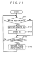
- FIG. 11 is a flowchart showing the second operation example of the mobile communication system according to the first embodiment.
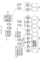
- FIG. 12 shows a second embodiment of a mobile communication.
- FIG. 13 shows a procedure for performing paging in the mobile communication system in FIG. 12.
- FIG. 14 is a sequence diagram showing the situation when paging is performed to a mobile node, which is in a master-slave relationship with a mobile router and is now dormant, in a first operation example of the mobile communication system according to the second embodiment.
- FIGS. 15A and 15B show flowcharts showing an example of an algorithm for controlling a flag in the mobile communication system according to the second embodiment, and FIG. 15A shows the operation performed when origination/termination for MN is occurred and FIG. 15B shows the operation performed when communication ends;
- FIG. 16 is a sequence diagram showing the situation when paging is performed to a mobile node, which is in a master-slave relationship with a mobile router and is now dormant, in a second operation example of the mobile communication system according to the second embodiment.
- FIG. 17 is a sequence diagram showing a third operation example of the mobile communication system according to the second embodiment.
- the system is configured to include a location manager LM#1 for storing LA information for mobile nodes and a mobile router, or master-slave relationship information indicating a master-slave relationship between the mobile router and the mobile nodes; a routing manager RM#1 (hereinafter referred to as RM for short) for storing routing address (hereinafter referred to as RA for short) information for the MNs and the MR; and ARs 1 to 11 for signaling an area identification (hereinafter referred to as Arl for short) to the mobile nodes and the mobile router and retaining a correspondence relationship between the Arl and area address managed as an LA within a network.
- a location manager LM#1 for storing LA information for mobile nodes and a mobile router, or master-slave relationship information indicating a master-slave relationship between the mobile router and the mobile nodes
- a routing manager RM#1 hereinafter referred to as RM for short
- RA routing address
- ARs 1 to 11 for signaling an area identification (her
- the system is configured to include a mobile router MR#1 performing LU of MNs existing in the space in a moving body on behalf of the MNs during movement in a dormant state, and mobile nodes MN#1 and MN#2 which do not perform LU when they are in the same space in a moving body with the mobile router MR#1, even if they are in a dormant state.
- Each of location areas LA#A, LA#B, LA#C, LA#D, ..., LA#Z is a set of multiple areas, each of which is associated with each of the ARs.
- a router or a switch for transferring a signal between AR and LM/RM or between LM and RM.
- RA information for the MR#1 and the MN#1 there are stored RA information for the MR#1 and the MN#1. That is, it is registered that the RA information for the identification (ID) "MN#1" is "AR3a” and the RA information for the identification (ID) "MR#1” is "AR3b" (S1302).
- an MR should send an LU signal whether it is dormant or active.
- an RM retaining routing addresses for the MR and MNs retains more detailed location information (RA information) than an LA, which is indicated by an AR for the area where the MR exists, and therefore it is inefficient, from a viewpoint of consumption of finite wireless resources, that information in an LM is updated by the MR sending an LU signal.
- a flag for determining whether an MR is dormant or active is retained in a table in an LM.
- the LM determines the state of the MR. If the MR is determined to be active, the LM inquires of the RM about RA information for the MR, and performs paging to the address indicated by the obtained RA information.
- the MR when receiving an activation signal from the MN#1, which is going to perform origination (S1401), the MR sends an activation notification signal to the LM#1 and the RM#1 (S1402a and S1402b).
- the LM#1 sets "1" as a value of a flag for an entry with an identification (ID) "MR#1" in its table (S1403a).
- IDs identifications
- RA information is written (S1403b).
- the value "1" of the flag means an active state and the value "0" of the flag means a dormant state (being not active).
- the RM#1 receiving the termination, sends a paging request (paging req) to the LM#1 (S1408) because it does not retain RA information for the dormant MN#2.
- the LM#1 detects that the MN#2 is dependent on the MR#1 and that the MR#1 is active. The LM#1 therefore inquires of the RM#1 about a routing address for the MR#1 (S1409). In response to this, the routing address for the MR#1 "AR3b" is sent from the RM#1 and inputted into the LM#1 (S1410). The LM#1 performs paging to the MN#2 using the routing address "AR3b" (S1411). Receiving this, the MR#1 sends a paging signal to the MN#2 (S1412). The MN#2 is then active and in communication with the origination source.
- FIGS. 3 and 4 show the operations performed by the mobile nodes MN#1 and MN#2, the mobile router MR#1, access routers AR1, AR2 and AR3, the LM#1 and the RM#1. These figures are associated with the block diagram shown in FIG. 1.
- FIG. 3 is a sequence diagram showing the situation when paging is performed to the MN#2 which is in a master-slave relationship with the MR#1 and is now dormant.
- RA information for the active MR#1 and MN#1 is stored in the RM#1. That is, it is registered that the RA information for the identification (ID) "MN#1" is "AR3a” and that the RA information for the identification (ID) "MR#1” is "AR3b” (S1501b).
- the mobile node MN#1 exists in the moving network (S1502a), and the mobile node MN#2 also exists in the moving network (S1502b).
- the mobile router MR#1 has sent an advertisement indicating that the Arl is "MR#1" to all the mobile nodes (MN#1 and MN#2) within the moving network (S1503).
- the mobile nodes MN#1 and MN#2 and the mobile router MR#1 have received an advertisement indicating that the Arl is "LA#B", from the access router AR3 (S1504).
- the RM#1 receives the termination from the mobile node MN#2 which is in a master-slave relationship with the MR#1 and is now dormant (S1505). If the RM#1, receiving the termination, searches for its table. If it detects that there is no entry about the MN#2, it recognizes that the MN#2 is dormant. The RM#1 then identifies the LM#1 as the LM for the MN#2 using the identification IPha, which is a specific address, as a key, and sends a paging request (S1506).
- the LM#1 searches for its table and detects that the MN#2 is dependent on the MR#1 and the MR#1 exists in the LA#A. The LM#1 then refers to the flag for the MR#1. Since the value of the flag for the MR#1 is "1" then, the LM#1 detects that the MR#1 is active (S1507).
- FIGS. 4A and 4B show examples of an algorithm for controlling the flag.
- the MN when origination/termination for MN is occurred (step S1600), the MN sends an activation signal to an MR (step S1601).
- the MR grasps the number of active MNs based on the activation/deactivation signal, which is sent when origination/termination for MN is occurred or when communication ends.
- the value changes from "0" to "1" and vice versa, it is notified to the LM.
- the LM controls setting and putting down of the flag, that is, setting of the flag for the MR.
- the flag for an MR is set to a value indicating an active state in response to a signal which is sent from a mobile node and indicates start of communication, and set to a value indicating a dormant state in response to a signal which is sent from a mobile node and indicates end of communication.
- the LM#1 which has detected that the MR#1 is active from the value of the flag "1 ", inquires of the RM#1 about RA information for the MR#1 (S1508). Receiving this inquiry, the RM#1 searches for its table and responds with "AR3b", which is RA information for the MR#1 (S1509). Receiving the response, the LM#1 performs paging to the "AR3b", which is the obtained RA information (S1510). This paging signal is transferred to the MR#1 via the AR3 (S1511), and the MR#1, receiving it, signals it to the nodes within the moving body (S1512). In this manner, the paging signal reaches the MN#2.
- the mobile node MN#2 sends a response (Paging Ack) in response to the paging signal (S1513)
- the response is inputted into the RM#1 via the mobile router MR#1, the access router AR3 and the LM#1 (S1514, S1515 and S1516).
- an LM is configured to include a table 71 for storing LAs for mobile nodes and a mobile router, and flags indicating whether they are active or dormant; an RA information inquiring function 72 for inquiring of an RM about RA information; a paging function 73 for performing paging with the use of the RA information obtained as a result of the inquiry or LA information it retains; a flag control function 74 for rewriting the value of the flag; an LA information update function 75 for updating LA information registered with the LM itself; and a signal sending/receiving portion 70 forming an interface for sending/receiving a signal between external apparatuses, such as an AR and an RM, and each portion within the LM itself.
- a table 71 for storing LAs for mobile nodes and a mobile router, and flags indicating whether they are active or dormant
- an RA information inquiring function 72 for inquiring of an RM about RA information
- a paging function 73 for
- an RM is configured to include a table 81 for storing RA information for mobile nodes and a mobile router; an RA information reply function 82 for replying RA information in response to an inquiry by an LM; an RA information update function 83 for updating RA information registered with the RM itself; a paging request sending function 84 for sending a paging request; and a signal sending/receiving portion 80 forming an interface for sending/receiving a signal between external apparatuses, such as an AR and an LM, and each portion within the RM itself.
- FIG. 6 is a flowchart showing the operation of the LM shown in FIG. 5 and the RM shown in FIG. 6.
- flags are stored in the table in the LM, which indicate whether the mobile nodes and the mobile router are active or dormant (step S901). It is then determined whether there has been received paging request to any mobile node (step S902). If there has been received paging request, the value of the flag for the mobile router, which is stored in the table, is checked (step S903).
- the LM performs paging to the mobile node using LA information stored in the table in the LM (from step S903 to S904).
- the LM inquires of the RM about RA information for the mobile router (from step S903 to S905).
- the LM then performs paging to the mobile node using the RM information obtained from a response returned to the LM by the RM in response to the inquiry (step S906).
- the operation described above makes it possible to perform paging to a mobile node which is in a master-slave relationship with a mobile router moving in an active state, without the mobile router consuming finite wireless resources to send an LU signal. Furthermore by performing paging with the use of RA information, which is more detailed location information than LA information, it is possible to minimize consumption of wireless resources required for performing paging.
- FIG. 8 shows the operations performed by the mobile nodes MN#1 and MN#2, the mobile router MR#1, the access routers AR3 and AR4, the LM#1 and the RM#1. The figure is associated with the block diagram shown in FIG. 1.
- FIG. 8 is a sequence diagram showing the situation when location update is performed utilizing a procedure for updating RA information for the MR#1 and the MN#1 which are active. It is assumed here that the MR#1 and the MN#1 moved from management by the AR3 to management by the AR4 while they being active.
- the mobile node MN#1 exists in the moving network (S1702a), and the mobile node MN#2 also exists in the moving network (S1702b).
- the mobile router MR#1 has sent an advertisement indicating that the Arl is "MR#1" to all the mobile nodes (MN#1 and MN#2) within the moving network (S1703).
- the mobile nodes MN#1 and MN#2 and the mobile router MR#1 have received an advertisement indicating that the Arl is "LA#B", from the access router AR4 (S1704).
- RA information for the MR#1 and the MN#1 in the RM#1 is updated in response to an activation signal (S1705 and S1706) signaled by the MR#1 as a representative.
- an activation signal S1705 and S1706
- the RM#1 sends a notification (IPra push) about RA information for the MR#1 to the LM#1 (S1708).
- IPra push a notification about RA information for the MR#1 to the LM#1
- the LM#1 stores the RA information as the LA information for MR#1.
- ID the identification
- AR4b the LA for the identification
- the LM#1 After the registration, the LM#1 sends a response (IPra push Ack) (S1710).
- IPra push Ack IPra push Ack
- a response to the activation signal is inputted into the mobile router MR#1 via the access router AR4 (S1711 and S1712).
- the LM is configured to include a table 76 for storing LA information for mobile nodes and a mobile router; a paging function 77 for performing paging for using RA information stored in the table 76; an LA information update function 78 for updating LA information registered with the LM itself; and a signal sending/receiving portion 70 forming an interface for sending/receiving a signal between external apparatuses, such as an AR and an RM, and each portion within the LM itself.
- Updated RA information notified by the RM is stored in a table 76 as LA information.
- an RM is configured to include a table 85 for storing RA information for mobile nodes and a mobile router; an RA information notification function 86 for, when RA information for a mobile router stored in the table 85 is updated, notifying the updated RA information to an LM; an RA information update function 87 for updating RA information registered with the RM itself; a paging request sending function 88 for sending a paging request; and a signal sending/receiving portion 80 forming an interface for sending/receiving a signal between external apparatuses such as an AR and an LM, and each portion within the RM itself.
- step S111 it is determined first in the RM whether the RA information for the active mobile router has been updated.
- the updated RA information is notified to the LM from the RM (from step S111 to S112).
- the notified RA information is then stored in the table in the LM (step S113).
- step S114 It is then determined in the LM whether there has been received paging request to a mobile node (step S114). If there has been received paging request, the LM performs paging to the mobile node using the RA information for the mobile router which is stored in the table in the LM itself (step S114 to S115). If no paging request has been received, the process returns to step S111 to determine in the RM whether the RA information has been updated (step S114 to S111). The above process is repeatedly executed.
- the operation described above makes it possible to perform paging to a mobile node which is in a master-slave relationship with the mobile router without retaining a flag in the table in the LM. Furthermore, by performing paging with the use of RA information, which is more detailed location information than LA information, it is possible to minimize consumption of wireless resources required for performing paging.
- FIG. 12 shows a second embodiment of a mobile communication system.
- a location manager with a two-hierarchical structure is adopted in this embodiment, which is constituted by a local location manager (hereinafter referred to as LLM for short) and a home location manager (hereinafter referred to as HLM for short).
- LLM local location manager
- HLM home location manager
- a routing manager one with a two-hierarchical structure is also adopted, which is constituted by a local routing manager (hereinafter referred to LRM for short) and a home routing manager (hereinafter referred to as HRM for short).
- this system is configured to include local location managers LLM#1, LLM#2 and LLM#3 for storing LA information for mobile nodes and a mobile router, or master-slave relationship information indicating a master-slave relationship between the mobile router and the mobile nodes; a home location manager HLM#1 for storing LLM information, which is information on an LLM for the area where the mobile node and the mobile router MR#1 exist; local routing managers LRM#1, LRM#2 and LRM#3 for storing RA information for MNs and MRs; a home routing manager HRM#1 for storing information on an LRM for the area where the MNs and the MRs exist; and ARs 1 to 11 for notifying an Arl to a mobile node or a mobile router and retaining a correspondence relationship between the Arl and location area information managed within the network as an LA. That is, there is a hierarchical structure for each of the location manager and the routing manger in this embodiment.
- this system is configured to include the mobile router MR#1 performing LU on behalf of MNs existing in the space in a moving body while the mobile router MR#1 and the MNs are moving in a dormant state; and mobile nodes MN#1 and MN#2, which do not perform LU when they are in the same space with the mobile router MR#1, even if they are dormant.
- Each of location areas LA#A, LA#B, LA#C, LA#D, ..., LA#Z is a set of multiple areas, each of which is associated with each of the ARs.
- a router or a switch for transferring a signal between AR and LLM/LRM, between LLM/LRM and HLM/HRM, and between LLM/LRM and LLM/LRM.
- the LRM#1 there is stored RA information for the MR#1 and the MN#1 which are active. That is, it is registered that the RA information for the identification (ID) "MN#1" is "AR3a” and that RA information for the identification (ID) "MR#1” is "AR3b” (S102).
- LLM information for the identifications (IDs) "MN#1", MN#2" and “MR#1" is "LLM#1" (S103).
- an MR should send an LU signal whether it is dormant or active.
- an LRM retaining routing addresses for the MR and MNs retains more detailed location information (RA information) than an LA, which is indicated by an AR for the area where the MR exists, and therefore it is inefficient from a viewpoint of consumption of finite wireless resources, that information in an LLM is updated by the MR sending an LU signal.
- a flag for determining whether an MR is dormant or active is retained in a table in an LLM.
- the LLM determines the state of the MR. If the MR is determined to be active, the LLM inquires of the LRM about RA information for the MR, and performs paging to the address indicated by the obtained RA information.
- the MR when receiving an activation signal from the MN#1, which is going to perform origination (S201), the MR sends an activation notification signal to the LLM#1 and the LRM#1 (S202a and S202b).
- the LLM#1 sets "1" as a value of a flag for an entry for the identification (ID) "MR#1" in its table (S203a).
- RA information is written (S203b).
- the HRM#1 receiving the termination, sends a paging request (paging req) to the HLM#1 (S208) because it does not retain LRM information for the dormant MN#2.
- the HLM#1 sends the paging request to the LLM#1 (S209).
- the LLM#1 detects that the MN#2 is dependent on the MR#1 and that the MR#1 is active. The LLM#1 therefore inquires of the LRM#1 about a routing address for the MR#1 (S210). In response to this, the routing address for the MR#1 "AR3b" is sent from the LRM#1 and inputted into the LLM#1 (S211). The LLM#1 performs paging to the MN#2 using the routing address "AR3b" (S212). Receiving this, the MR#1 sends a paging signal to the MN#2 (S213). The MN#2 is then active and in communication with the origination source.
- FIGS. 14 and 15 show the operations performed by the mobile nodes MN#1 and MN#2, the mobile router MR#1, access routers AR1, AR2 and AR3, the LRM#1, the LLM#1, the HLM#1 and the HRM#1. These figures are associated with the configuration shown in FIG. 12.
- FIG. 14 is a sequence diagram showing the situation when paging is performed to the MN#2 which is in a master-slave relationship with the MR#1 and is now dormant.
- RA information for the active MR#1 and MN#1 is stored in the LRM#1. That is, it is registered that the RA information for the identification (ID) "MN#1" is "AR3a” and that the RA information for the identification (ID) "MR#1” is "AR3b" (S301a).
- the mobile node MN#1 exists in the moving network (S302a), and the mobile node MN#2 also exists in the moving network (S302b).
- the mobile router MR#1 has sent an advertisement indicating that the Arl is "MR#1" to all the mobile nodes (MN#1 and MN#2) within the moving network (S303).
- the mobile nodes MN#1 and MN#2 and the mobile router MR#1 have received an advertisement indicating that the Arl is "LA#B", from the access router AR3 (S304).
- the HRM#1 receiving the termination, searches for its table. If it detects that there is no entry about the MN#2, it recognizes that the MN#2 is dormant. The HRM#1 then identifies the HLM#1 as the HLM for the MN#2 using the identification IPha, which is a specific address, as a key, and sends a paging request (S306). Receiving this paging request, the HLM#1 searches for its table, detects that the MN#2 is under management by the LLM#1 and transfers the paging request to the LLM#1 (S307).
- the LLM#1 searches for its table and detects that the MN#2 is dependent on the MR#1 and the MR#1 exists in the LA#A. The LLM#1 then refers to the flag for the MR#1. Since the value of the flag for the MR#1 is "1", the LLM#1 detects that the MR#1 is active (S308).
- FIGS. 15A and 15B show an example of an algorithm for controlling the flag.
- the MN when origination/termination for MN is occurred (step S400), the MN sends an activation signal to an MR (step S401).
- the MR grasps the number of active MNs based on the activation/deactivation signal which is sent when origination/termination for MN is occurred or when communication is finished.
- the value changes from "0" to "1" and vice versa, it is notified to the LLM.
- the LLM controls setting and putting down of the flag, that is, setting for the flag for the MR.
- the flag for an MR is set to a value indicating an active state in response to a signal which is sent from a mobile node and indicates start of communication, and set to a value indicating a dormant state in response to a signal which is sent from a mobile node and indicates end of communication.
- the LLM#1 which has detected that the MR#1 is active from the value of the flag "1" inquires of the LRM#1 about RA information for the MR#1 (S309). Receiving this inquiry, the LRM#1 searches for its table and responds with "AR3b", which is RA information for the MR#1 (S310). Receiving the response, the LLM#1 performs paging to the "AR3b", which is the obtained RA information (S311). This paging signal is transferred to the MR#1 via the AR3 (S312) and signaled by the MR#1, which has received it, to the nodes within the moving body (S313). In this manner, the paging signal reaches the MN#2.
- the mobile node MN#2 sends a response (Paging Ack) in response to the paging signal (S314)
- the response is inputted into the HRM#1 via the mobile router MR#1, the access router AR3, the LLM#1 and the HLM#1 (S315, S316 S317 and S318).
- the configurations of the LLM and the LRM for realizing the above operation are similar to those of the LM and the RM shown in FIGS. 5 and 6, and description therefor is omitted here.
- the operations of the LLM and the LRM are similar to those in FIG. 7 described above, and description therefor is also omitted here.
- FIG. 16 is associated with the block diagram shown in FIG. 12.
- the figure is a sequence diagram showing the situation when paging is performed to the MN#2 which is in a master-slave relationship with the MR#1 and is now dormant. It is assumed that the MR#1 and the MN#1 became active when they were in the LA#A and have moved from management by the AR2 included in the LA#A to management by the AR6 included in the LA#C while being active, and that RA information for the active MR#1 and MN#1 is stored in the LRM#2.
- the mobile node MN#1 exists in the moving network (S502a), and the mobile node MN#2 also exists in the moving network (S502b).
- the mobile router MR#1 has sent an advertisement indicating that the Arl is "MR#1" to all the mobile nodes (MN#1 and MN#2) within the moving network (S503).
- the mobile nodes MN#1 and MN#2 and the mobile router MR#1 have received an advertisement indicating that the Arl is "LA#C", from the access router AR6 (S504).
- the HRM#1 receiving the termination, searches for its table. If it detects that there is no entry about the MN#2, it recognizes that the MN#2 is dormant. The HRM#1 then identifies the HLM#1 as the HLM for the MN#2 using the identification IPha, which is a specific address, as a key, and sends a paging request (S506). Receiving this paging request, the HLM#1 searches for its table, detects that the MN#2 is under management by the LLM#1 and transfers the paging request to the LLM#1 (S507).
- the LLM#1 searches for its table and detects that the MN#2 is dependent on the MR#1 and that the MR#1 exists in the LA#A. The LLM#1 then refers to the flag for the MR#1. Since the value of the flag for the MR#1 is "1" then, the LLM#1 detects that the MR#1 is active (S508).
- the LLM#1 Detecting that the MR#1 is active from the value of the flag "1 ", the LLM#1 inquires of the LRM#1 about RA information for the MR#1 (S509). Receiving this inquiry, the LRM#1 searches for its table. The LRM#1, detecting that there is no entry about the MR#1 in its table as a search result, identifies the HRM#1 as an HRM for the MR#1, using the IPha as a key, and sends a request for inquiring about the LRM information for the MR#1 which is managed by the identified HRM#1 (S510).
- the HRM#1 searches for its table and responds that the MR#1 is under management by the LRM#2 (S511). Receiving this response, the LRM#1 sends a request for inquiring of the LRM#2 about RA information for the MR#1 (S512).
- the LRM#2 searches for its table and responds to the LRM#1 with AR6b, which is the RA information for the MR#1 (S513). Receiving this response, the LRM#1 transfers it to the LLM#1 (S514).
- the LLM#1 then performs paging to the "AR6b", which is the obtained RA information (S515).
- This paging signal is transferred to the MR#1 via the AR6 (S516), and the MR#1, receiving it, signals it to the nodes within the moving body (S517). In this manner, the paging signal reaches the MN#2.
- the mobile node MN#2 sends a response (Paging Ack) in response to the paging signal (S518)
- the response is inputted into the HRM#1 via the mobile router MR#1, the access router AR6, the LLM#1 and the HLM#1 (S519, S520, S521 and S522).
- FIG. 17 is associated with the block diagram shown in FIG. 12.
- FIG. 17 is a sequence diagram showing the situation when location update is performed utilizing a procedure for updating RA information for the MR#1 and the MN#1 which are active. It is assumed here that the MR#1 and the MN#1 have moved from management by the AR3 to management by the AR4 while being active.
- the mobile node MN#1 exists in the moving network (S602a), and the mobile node MN#2 also exists in the moving network (S602b).
- the mobile router MR#1 has sent an advertisement indicating that the Arl is "MR#1" to all the mobile nodes (MN#1 and MN#2) within the moving network (S603).
- the mobile nodes MN#1 and MN#2 and the mobile router MR#1 have received an advertisement indicating that the Arl is "LA#B", from the access router AR4 (S604).
- the LRM#1 sends notification about the RA information for the MR#1 (IPra push) to the LLM#1 (S608).
- the LLM#1 stores the RA information as LA information for the MR#1.
- the LA for the identification (ID) "MR#1" is "AR4b" (S609).
- the paging is performed to the routing address.
- the configurations of the LLM and the LRM for realizing the above operation are similar to those of the LM and the RM shown in FIGS. 9 and 10, and description therefor is omitted here.
- the operations of the LLM and the LRM are similar to those in FIG. 11 described above, and description therefor is also omitted here.
- the operation described above makes it possible to perform paging to a mobile node which is in a master-slave relationship with the mobile router without retaining a flag in the table in the LLM, unlike the first and second operation examples. Furthermore, by performing paging with the use of RA information, which is more detailed location information than LA information, it is possible to minimize consumption of wireless resources required for performing paging.
- a flag for determining whether a mobile router is dormant or active is retained in a location manager; the location manager determines the state of the mobile router when paging is performed to a mobile node which is in a master-slave relationship with the mobile router; the location manager, when the mobile router is determined to be active, inquires of a routing manager about routing address information for the mobile router performs paging to the address indicated by the obtained routing address information.
- the present invention is advantageous in making it possible to perform paging to a mobile node which is in a master-slave relationship with a mobile router moving in an active state, without the mobile router consuming finite wireless resources to send a location update signal.
- the present invention is advantageous in making it possible to easily recognize whether the state is active or dormant by controlling the value of a flag with the utilization of a signal which indicates start/end of an active state.
- the present invention is advantageous in making it possible to perform paging to a mobile node which is in a master-slave relationship with a mobile router, without retaining a flag by notifying, each time a routing address is updated, the updated routing address to a location manager and retaining it as location area information.
- the present invention is also advantageous in making it possible to minimize consumption of wireless resources required for performing paging by performing paging with the use of a routing address which indicates more detailed location information than location area information.
Landscapes
- Engineering & Computer Science (AREA)
- Computer Networks & Wireless Communication (AREA)
- Signal Processing (AREA)
- Mobile Radio Communication Systems (AREA)
- Data Exchanges In Wide-Area Networks (AREA)
Applications Claiming Priority (2)
| Application Number | Priority Date | Filing Date | Title |
|---|---|---|---|
| JP2003022450A JP2004236001A (ja) | 2003-01-30 | 2003-01-30 | 移動通信システム、位置情報管理装置、ルーティング情報管理装置 |
| JP2003022450 | 2003-01-30 |
Publications (2)
| Publication Number | Publication Date |
|---|---|
| EP1443793A1 true EP1443793A1 (fr) | 2004-08-04 |
| EP1443793B1 EP1443793B1 (fr) | 2006-03-22 |
Family
ID=32652899
Family Applications (1)
| Application Number | Title | Priority Date | Filing Date |
|---|---|---|---|
| EP20040001893 Expired - Lifetime EP1443793B1 (fr) | 2003-01-30 | 2004-01-29 | Système de communication mobile, gestionnaire de position et gestionnaire d'acheminement |
Country Status (5)
| Country | Link |
|---|---|
| US (1) | US7519025B2 (fr) |
| EP (1) | EP1443793B1 (fr) |
| JP (1) | JP2004236001A (fr) |
| CN (1) | CN1272973C (fr) |
| DE (1) | DE602004000500T2 (fr) |
Families Citing this family (11)
| Publication number | Priority date | Publication date | Assignee | Title |
|---|---|---|---|---|
| US7557433B2 (en) * | 2004-10-25 | 2009-07-07 | Mccain Joseph H | Microelectronic device with integrated energy source |
| CN101523843B (zh) * | 2006-08-09 | 2013-01-02 | 艾利森电话股份有限公司 | 路由管理器分层结构 |
| WO2008018150A1 (fr) * | 2006-08-09 | 2008-02-14 | Telefonaktiebolaget Lm Ericsson (Publ) | Sélection de vrm |
| US9066316B2 (en) * | 2007-11-19 | 2015-06-23 | Qualcomm Incorporated | Diagnostic monitoring by a wireless device |
| CN101877818B (zh) * | 2009-04-30 | 2015-08-12 | 中兴通讯股份有限公司 | 定位业务辅助数据更新通知的方法及系统 |
| CN102036220A (zh) * | 2009-09-25 | 2011-04-27 | 华为技术有限公司 | 一种移动性管理方法及装置 |
| US9258201B2 (en) * | 2010-02-23 | 2016-02-09 | Trane International Inc. | Active device management for use in a building automation system |
| KR101404287B1 (ko) * | 2010-03-12 | 2014-06-05 | 후지쯔 가부시끼가이샤 | 통신 구간 설정 방법, 중계국, 이동 통신 시스템 |
| FR2988969A1 (fr) * | 2012-03-29 | 2013-10-04 | France Telecom | Procede et equipement de routage pour communication entre vehicules |
| JP5794549B2 (ja) * | 2014-01-16 | 2015-10-14 | ▲ホア▼▲ウェイ▼技術有限公司 | ページング方法及びページング装置 |
| WO2017002179A1 (fr) * | 2015-06-29 | 2017-01-05 | 三菱電機株式会社 | Station de base et appareil de transfert |
Citations (2)
| Publication number | Priority date | Publication date | Assignee | Title |
|---|---|---|---|---|
| JPH0555991A (ja) * | 1991-08-23 | 1993-03-05 | Nippon Telegr & Teleph Corp <Ntt> | 位置登録方式 |
| EP1237389A2 (fr) * | 2001-02-28 | 2002-09-04 | NTT DoCoMo, Inc. | Procédé et système permettant d'éviter de mise à jour de localisation de terminal mobile dans un train et un système d'offrir des informations de localisation |
Family Cites Families (17)
| Publication number | Priority date | Publication date | Assignee | Title |
|---|---|---|---|---|
| JP2689990B2 (ja) | 1988-12-16 | 1997-12-10 | 日本情報通信コンサルティング株式会社 | 移動体通信装置の位置識別方式 |
| JP2878397B2 (ja) | 1990-06-08 | 1999-04-05 | 日本電信電話株式会社 | 通信中着信制御方式 |
| JP2667757B2 (ja) | 1992-03-16 | 1997-10-27 | 富士通株式会社 | 移動交換機システムにおける移動局の位置登録方法 |
| JPH1146380A (ja) | 1997-07-28 | 1999-02-16 | Nec Corp | セルラ方式の移動通信システム |
| KR100272567B1 (ko) * | 1997-12-31 | 2000-11-15 | 서평원 | 이동통신 네트워크를 이용한 이동 인터넷 |
| JP4578585B2 (ja) | 1998-02-13 | 2010-11-10 | 富士通株式会社 | 移動通信システム、移動基地局、及びその制御方法 |
| JP3127957B2 (ja) * | 1998-06-09 | 2001-01-29 | 日本電気株式会社 | 移動通信システムにおける位置登録方法 |
| US7136645B2 (en) * | 1998-10-09 | 2006-11-14 | Netmotion Wireless, Inc. | Method and apparatus for providing mobile and other intermittent connectivity in a computing environment |
| US6636498B1 (en) * | 1999-01-08 | 2003-10-21 | Cisco Technology, Inc. | Mobile IP mobile router |
| US7173917B1 (en) * | 2000-03-31 | 2007-02-06 | Nortel Networks Limited | Unicast agent advertisement based on layer 2 and layer 3 motion detection |
| US6961573B1 (en) * | 2000-12-22 | 2005-11-01 | Cisco Technology, Inc. | System and method for routing communications based on wireless communication link quality |
| US6804532B1 (en) * | 2000-12-22 | 2004-10-12 | Cisco Technology, Inc. | System and method for re-routing communications based on wireless communication link quality |
| US7206294B2 (en) * | 2001-08-15 | 2007-04-17 | Meshnetworks, Inc. | Movable access points and repeaters for minimizing coverage and capacity constraints in a wireless communications network and a method for using the same |
| US6721297B2 (en) * | 2001-11-19 | 2004-04-13 | Motorola, Inc. | Method and apparatus for providing IP mobility for mobile networks |
| US7039404B2 (en) * | 2002-06-27 | 2006-05-02 | Intel Corporation | Continuous mobility across wireless networks by integrating mobile IP and GPRS mobility agents |
| US7110377B2 (en) * | 2002-10-10 | 2006-09-19 | Qualcomm Incorporated | Dormant handoff in a packet data network |
| US6925378B2 (en) * | 2003-05-12 | 2005-08-02 | Circumnav Networks, Inc. | Enhanced mobile communication device with extended radio, and applications |
-
2003
- 2003-01-30 JP JP2003022450A patent/JP2004236001A/ja active Pending
-
2004
- 2004-01-27 US US10/764,481 patent/US7519025B2/en not_active Expired - Fee Related
- 2004-01-29 DE DE200460000500 patent/DE602004000500T2/de not_active Expired - Lifetime
- 2004-01-29 EP EP20040001893 patent/EP1443793B1/fr not_active Expired - Lifetime
- 2004-01-30 CN CNB2004100037750A patent/CN1272973C/zh not_active Expired - Fee Related
Patent Citations (2)
| Publication number | Priority date | Publication date | Assignee | Title |
|---|---|---|---|---|
| JPH0555991A (ja) * | 1991-08-23 | 1993-03-05 | Nippon Telegr & Teleph Corp <Ntt> | 位置登録方式 |
| EP1237389A2 (fr) * | 2001-02-28 | 2002-09-04 | NTT DoCoMo, Inc. | Procédé et système permettant d'éviter de mise à jour de localisation de terminal mobile dans un train et un système d'offrir des informations de localisation |
Non-Patent Citations (1)
| Title |
|---|
| PATENT ABSTRACTS OF JAPAN vol. 017, no. 359 (E - 1395) 7 July 1993 (1993-07-07) * |
Also Published As
| Publication number | Publication date |
|---|---|
| US7519025B2 (en) | 2009-04-14 |
| US20040258011A1 (en) | 2004-12-23 |
| CN1272973C (zh) | 2006-08-30 |
| EP1443793B1 (fr) | 2006-03-22 |
| JP2004236001A (ja) | 2004-08-19 |
| CN1520201A (zh) | 2004-08-11 |
| DE602004000500T2 (de) | 2006-11-30 |
| DE602004000500D1 (de) | 2006-05-11 |
Similar Documents
| Publication | Publication Date | Title |
|---|---|---|
| JP3049056B1 (ja) | 移動体通信網の加入者デ―タ制御方法 | |
| US6549775B2 (en) | Mobile communication system | |
| JP2853688B2 (ja) | パーソナル通信システムのモビリティ管理方式 | |
| EP1113691B1 (fr) | Procédé de gestion de localisation pour gestion de localisation d'un terminal mobile dans un système radiotéléphonique de communication par paquets, et système radiotéléphonique de communication par paquets | |
| EP1443793B1 (fr) | Système de communication mobile, gestionnaire de position et gestionnaire d'acheminement | |
| EP1460869B1 (fr) | Gestionnaire de localisation recevant des informations d'enregistrement envoyées par un routeur mobile | |
| US20130059611A1 (en) | Wireless communication system, communication control method, mobility management apparatus, mobile terminal and base station | |
| CN102118733A (zh) | 一种用户设备请求SMSonly功能时的处理方法及设备 | |
| US20110287734A1 (en) | Mobile communication system, located area management device, communication control device and communication method | |
| JP2800455B2 (ja) | 移動通信システムの位置登録方式および呼出し方式 | |
| CN109076489A (zh) | 附着方法、寻呼方法、装置和设备 | |
| JP4641311B2 (ja) | 移動通信システム、位置情報管理装置 | |
| JP2009267709A (ja) | 無線ネットワークシステムおよび無線システム選択方法 | |
| JP3593974B2 (ja) | 通信方法および通信端末 | |
| JP2010226602A (ja) | 移動通信システム、移動端末、基地局および周辺セル情報取得方法 | |
| JPH09215031A (ja) | 移動体通信システム | |
| JP4619933B2 (ja) | ページング方法 | |
| JP2728728B2 (ja) | 移動通信追跡接続制御方式 | |
| KR101105243B1 (ko) | 대중교통 시스템을 위한 그룹 위치 관리 시스템 및 그 방법 | |
| KR100292443B1 (ko) | 무선통신시스템에서의페이징영역등록방법및그를이용한다단계페이징방법 | |
| JPH08289355A (ja) | 移動体通信端末位置情報伝達方法と装置および該装置を有する移動体通信システム | |
| CN1992965B (zh) | 实现组呼业务的系统及实现组呼业务的方法 | |
| JP4001832B2 (ja) | 位置管理システム、移動端末、アクセスルータ、ローカル位置情報管理装置、ホーム位置情報管理装置、位置管理方法 | |
| JP4575404B2 (ja) | ローカル位置情報管理装置、ホーム位置情報管理装置、移動通信システム | |
| KR20000061143A (ko) | 계층셀을 지원하는 이동통신 시스팀에서의 페이징 방법 |
Legal Events
| Date | Code | Title | Description |
|---|---|---|---|
| PUAI | Public reference made under article 153(3) epc to a published international application that has entered the european phase |
Free format text: ORIGINAL CODE: 0009012 |
|
| AK | Designated contracting states |
Kind code of ref document: A1 Designated state(s): AT BE BG CH CY CZ DE DK EE ES FI FR GB GR HU IE IT LI LU MC NL PT RO SE SI SK TR |
|
| AX | Request for extension of the european patent |
Extension state: AL LT LV MK |
|
| 17P | Request for examination filed |
Effective date: 20041120 |
|
| 17Q | First examination report despatched |
Effective date: 20041220 |
|
| AKX | Designation fees paid |
Designated state(s): DE GB |
|
| RBV | Designated contracting states (corrected) |
Designated state(s): DE GB |
|
| GRAP | Despatch of communication of intention to grant a patent |
Free format text: ORIGINAL CODE: EPIDOSNIGR1 |
|
| GRAS | Grant fee paid |
Free format text: ORIGINAL CODE: EPIDOSNIGR3 |
|
| GRAA | (expected) grant |
Free format text: ORIGINAL CODE: 0009210 |
|
| AK | Designated contracting states |
Kind code of ref document: B1 Designated state(s): DE GB |
|
| REG | Reference to a national code |
Ref country code: GB Ref legal event code: FG4D |
|
| REF | Corresponds to: |
Ref document number: 602004000500 Country of ref document: DE Date of ref document: 20060511 Kind code of ref document: P |
|
| PLBE | No opposition filed within time limit |
Free format text: ORIGINAL CODE: 0009261 |
|
| STAA | Information on the status of an ep patent application or granted ep patent |
Free format text: STATUS: NO OPPOSITION FILED WITHIN TIME LIMIT |
|
| 26N | No opposition filed |
Effective date: 20061227 |
|
| PGFP | Annual fee paid to national office [announced via postgrant information from national office to epo] |
Ref country code: DE Payment date: 20170125 Year of fee payment: 14 |
|
| PGFP | Annual fee paid to national office [announced via postgrant information from national office to epo] |
Ref country code: GB Payment date: 20170125 Year of fee payment: 14 |
|
| REG | Reference to a national code |
Ref country code: DE Ref legal event code: R119 Ref document number: 602004000500 Country of ref document: DE |
|
| GBPC | Gb: european patent ceased through non-payment of renewal fee |
Effective date: 20180129 |
|
| PG25 | Lapsed in a contracting state [announced via postgrant information from national office to epo] |
Ref country code: DE Free format text: LAPSE BECAUSE OF NON-PAYMENT OF DUE FEES Effective date: 20180801 |
|
| PG25 | Lapsed in a contracting state [announced via postgrant information from national office to epo] |
Ref country code: GB Free format text: LAPSE BECAUSE OF NON-PAYMENT OF DUE FEES Effective date: 20180129 |