EP1443802B1 - Hinter-dem-Ohr Hörgerät - Google Patents
Hinter-dem-Ohr Hörgerät Download PDFInfo
- Publication number
- EP1443802B1 EP1443802B1 EP04010550A EP04010550A EP1443802B1 EP 1443802 B1 EP1443802 B1 EP 1443802B1 EP 04010550 A EP04010550 A EP 04010550A EP 04010550 A EP04010550 A EP 04010550A EP 1443802 B1 EP1443802 B1 EP 1443802B1
- Authority
- EP
- European Patent Office
- Prior art keywords
- hose
- connecting element
- hearing device
- sound
- exit
- Prior art date
- Legal status (The legal status is an assumption and is not a legal conclusion. Google has not performed a legal analysis and makes no representation as to the accuracy of the status listed.)
- Expired - Lifetime
Links
Images

Classifications
-
- H—ELECTRICITY
- H04—ELECTRIC COMMUNICATION TECHNIQUE
- H04R—LOUDSPEAKERS, MICROPHONES, GRAMOPHONE PICK-UPS OR LIKE ACOUSTIC ELECTROMECHANICAL TRANSDUCERS; ELECTRIC HEARING AIDS; PUBLIC ADDRESS SYSTEMS
- H04R25/00—Electric hearing aids
- H04R25/60—Mounting or interconnection of hearing aid parts, e.g. inside tips, housings or to ossicles
- H04R25/607—Mounting or interconnection of hearing aid parts, e.g. inside tips, housings or to ossicles of earhooks
-
- H—ELECTRICITY
- H04—ELECTRIC COMMUNICATION TECHNIQUE
- H04R—LOUDSPEAKERS, MICROPHONES, GRAMOPHONE PICK-UPS OR LIKE ACOUSTIC ELECTROMECHANICAL TRANSDUCERS; ELECTRIC HEARING AIDS; PUBLIC ADDRESS SYSTEMS
- H04R2225/00—Details of deaf aids covered by H04R25/00, not provided for in any of its subgroups
- H04R2225/021—Behind the ear [BTE] hearing aids
- H04R2225/0213—Constructional details of earhooks, e.g. shape, material
-
- H—ELECTRICITY
- H04—ELECTRIC COMMUNICATION TECHNIQUE
- H04R—LOUDSPEAKERS, MICROPHONES, GRAMOPHONE PICK-UPS OR LIKE ACOUSTIC ELECTROMECHANICAL TRANSDUCERS; ELECTRIC HEARING AIDS; PUBLIC ADDRESS SYSTEMS
- H04R25/00—Electric hearing aids
- H04R25/65—Housing parts, e.g. shells, tips or moulds, or their manufacture
Definitions
- the present invention relates to a hearing aid in particular suitable for wearing on the auricle or behind the ear according to the wording of claim 1.
- hearing aids worn on the auricle or behind the ear have at the output for the acoustic signal a so-called hearing aid or a bent acoustic transmission element to which an acoustic connection hose is plugged for transmitting the signal or sound into the auditory canal.
- This arranged on the hearing aid transmission device including tube to the ear canal is conspicuous, fits usually not optimal to the anatomical events, and also can be due to the bending and heels in the acoustic transmission channel impedance jumps or disturbances in the sound transmission.
- a pre-formed connecting tube made of a stiff material for the transmission of the acoustic signal. It is disadvantageous that virtually every tube is specially adapted to the particular anatomy of an ear.
- a hearing aid is proposed, in particular suitable for wearing on the auricle or behind the ear, in accordance with the wording of claim 1.
- the invention proposes to arrange a tubular connection element at the acoustic output for connecting the output with a tube for sound or acoustic transmission in the ear canal whose bending angle ⁇ 80 ° is.
- connection element i. the inner diameter of the acoustic transmission channel in the connection element corresponds approximately to the outer diameter of the hose, so that the latter can be introduced into this acoustic transmission channel.
- hose firmly in the connecting element, for example by means of gluing, welding, by non-slip forming of the interface between hose and connecting element, etc.
- connection part for directly connecting the acoustic output to the hose, such as by forming a connecting piece, collar, etc.
- connection element The turn of the acoustic output of the hearing aid in the direction of the entrance of the ear canal can be achieved on the one hand by a curved formation of the connecting element, whereby commercially available usually flexible connecting hoses can be used. But it is also possible to form the connection element largely straight and to use an at least partially pre-bent sound tube.
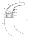
- Fig. 1 is shown schematically in section a hearing aid 1, having at its upper end an acoustic output 3, to which today a so-called hook 5 is arranged.
- a hose is plugged for the transmission of the acoustic or sound signal on or in the ear canal of an ear.
- a shortened connecting element 7 on the acoustic output 3 of the hearing aid 1 is now proposed instead of the mentioned hearing angle to arrange, in which connection element 7 of the sound tube 9 is guided.
- the hose 9 is preferably performed directly on a nozzle or connection nipple 13, which is formed on the acoustic output 3 of the hearing aid 1 above.
- the tube 9 is guided into the connection element 7, wherein the provided in the connection element 7 acoustic channel 8 has an inner diameter which corresponds approximately to the outer diameter of the tube 9.
- the tube 9 is held firmly on the acoustic output 3 of the hearing aid 1 by the connection element 7 is rotated and held on a thread 11 at the acoustic output.
- the hose 9 is fixedly connected to the connection element 7, for example by gluing or welding, so that it is impossible to tear it out.
- a pre-bent tube 9 can be used, which is preferably optimally adapted to the anatomy of the ear. Since it is known that no ear is the same as the other, the hose to be used is preferably selected from a series of "standard" pre-bent hoses. In general, connecting element 7 and the hose 9 form a unit, so that a selection of different angle / hose combinations is possible.
- a hose offered today on the market it is also possible to produce the bend on the hearing aid by means of a correspondingly more curved connecting element, as shown schematically and in section in FIG Fig. 3 shown. Contrary to the connection element in Fig. 2 is that in Fig. 3 much more bent and has an angle of about 60 to 70 °.
- a tube 9 which is usually offered today can be pushed through the acoustic passage 8 of the connection element 7 and in turn be firmly connected to the connection element. So that the bending during the insertion of the tube 9 is maintained, wedge-shaped fixing points 15 are preferably provided in the connection element 7.
- the acoustic transmission tube 9 is again pushed onto a connecting piece or connection nipple 13 at the acoustic output opening 3, whereby a largely continuous transition in the sound or acoustic transmission channel can be achieved.
- connection element 7 and sound transmission tube 9 which manifests itself in particular in reducing the conspicuousness when wearing a hearing device.
- a largely continuous transmission of the sound can be achieved and, moreover, the bending is largely uniform, so that the occurrence of impedance jumps or jumps in the sound transmission can be avoided or reduced.
- the Acousticians change a sound tube separately and the contra-angle is preserved.
- connection element 7 As well as the sound or acoustic transmission tube 9 can be done in various ways. Only the fact that the connecting element has a bend of at least ⁇ 80 °, is an essential distinguishing feature compared to today commonly used hooks or listening angles.
Landscapes
- Health & Medical Sciences (AREA)
- General Health & Medical Sciences (AREA)
- Neurosurgery (AREA)
- Otolaryngology (AREA)
- Physics & Mathematics (AREA)
- Engineering & Computer Science (AREA)
- Acoustics & Sound (AREA)
- Signal Processing (AREA)
- Headphones And Earphones (AREA)
Description
- Die vorliegende Erfindung betrifft ein Hörgerät insbesondere geeignet für das Tragen an der Ohrmuschel bzw. hinter dem Ohr gemäss dem Wortlaut nach Anspruch 1.
- An der Ohrmuschel bzw. hinter dem Ohr getragene Hörgeräte weisen in der Regel am Ausgang für das akustische Signal einen sogenannten Hörmittel bzw. ein gebogenes Akustikübertragungselement auf, an welches ein akustischer Verbindungsschlauch aufgesteckt wird zum Übertragen des Signals bzw. Schalls in den Gehörgang. Dieses am Hörgerät angeordnete Übertragungselement inkl. Schlauch zum Gehörgang ist auffällig, fügt sich in der Regel nicht optimal an die anatomischen Begebenheiten, und zudem können sich aufgrund der Biegung und Absätzen im akustischen Übertragungskanal Impedanzsprünge bzw. Störungen in der Schallübertragung einstellen. Entsprechend wird in der
W099/04601 - Es ist daher eine Aufgabe der vorliegenden Erfindung, eine Lösung für die oben beschriebene Problematik vorzuschlagen.
- Erfindungsgemäss vorgeschlagen wird ein Hörgerät, insbesondere geeignet für das Tragen an der Ohrmuschel bzw. hinter dem Ohr, entsprechend dem Wortlaut nach Anspruch 1.
- Entgegen des heute üblicherweise verwendeten sogenannten Hörwinkels, welcher direkt am akustischen Ausgang des Hörgerätes angeordnet ist und welcher in der Regel einen Biegewinkel von ca. 90° aufweist, wird erfindungsgemäss vorgeschlagen, am akustischen Ausgang ein rohrförmiges Anschlusselement anzuordnen für das Verbinden des Ausgangs mit einem Schlauch für die Schall- bzw. Akustikübertragung in den Ohrkanal, dessen Biegewinkel < 80° ist.
- Dabei wird gemäss einer Ausführungsvariante vorgeschlagen, den Schlauch in das Anschlusselement zu führen, d.h. der Innendurchmesser des akustischen Übertragungskanals im Anschlusselement entspricht etwa dem Aussendurchmesser des Schlauches, damit letzterer in diesen akustischen Übertragungskanal eingeführt werden kann.
- Weiter wird vorgeschlagen, den Schlauch im Anschlusselement fest anzuordnen, beispielsweise mittels Kleben, Schweissen, durch rutschfestes Aussbilden der Grenzfläche zwischen Schlauch und Anschlusselement, etc.
- Gemäss einer weiteren Ausführungsvariante wird vorgeschlagen, am akustischen Ausgang des Hörgerätes eine Anschlusspartie vorzusehen zum direkten Verbinden des akustischen Ausgangs mit dem Schlauch, wie beispielsweise durch Ausbilden eines Anschlussstutzens, Kragens, etc.
- Die Abbiegung vom Akustikausgang des Hörgerätes in Richtung Eingang des Gehörganges kann einerseits durch gebogenes Ausbilden des Anschlusselementes erzielt werden, wodurch handelsübliche in der Regel flexible Verbindungsschläuche verwendet werden können. Es ist aber auch möglich, das Anschlusselement weitgehendest gerade auszubilden und einen wenigstens teilweise vorgebogenen Schallschlauch zu verwenden.
- Weitere bevorzugte Ausführungsvarianten des erfindungsgemässen Hörgerätes bzw. der erfindungsgemäss vorgeschlagenen Anschluss- und Übertragungspartie sind in abhängigen Ansprüchen charakterisiert.
- Die Erfindung wird nun beispielsweise und unter Bezug auf die beigefügten Figuren näher erläutert.
- Dabei zeigen:
- Fig. 1
- schematisch im Schnitt ein Hörgerät, einerseits aufweisend einen heute üblicherweise verwendeten Hörwinkel, sowie erfindungsgemäss vorgeschlagene Anschluss- bzw. Übertragungselemente,
- Fig. 2
- im Schnitt in Vergrösserung einen erfindungsgemäss vorgeschlagenen Anschluss eines Schallschlauches direkt am akustischen Ausgang eines Hörgerätes und
- Fig. 3
- im Schnitt eine weitere Ausführungsvariante des Anordnens eines Schallschlauches am Akustikausgang eines Hörgerätes.
- In
Fig. 1 ist schematisch im Schnitt ein Hörgerät 1 dargestellt, aufweisend an seinem oberen Ende einen Akustikausgang 3, an welchem heute üblich ein sogenannter Hook 5 angeordnet ist. An der Endpartie 6 dieses Hörwinkels wird heute üblicherweise ein Schlauch aufgesteckt für das Übertragen des Akustik- bzw. Schallsignals am bzw. in den Gehörgang eines Ohres. - Gemäss der vorliegenden Erfindung wird nun vorgeschlagen, an Stelle des erwähnten Hörwinkels ein verkürztes Anschlusselement 7 am Akustikausgang 3 des Hörgerätes 1 anzuordnen, in welches Anschlusselement 7 der Schallschlauch 9 geführt ist.
- Wie in Vergrösserung im Schnitt in
Fig. 2 dargestellt, wird vorzugsweise der Schlauch 9 direkt auf einen Stutzen oder Anschlussnippel 13 geführt, welcher am Akustikausgang 3 des Hörgerätes 1 vorstehend ausgebildet ist. Dabei ist der Schlauch 9 in das Anschlusselement 7 hineingeführt, wobei der im Anschlusselement 7 vorgesehene Akustikkanal 8 einen Innendurchmesser aufweist, welcher etwa dem Aussendurchmesser des Schlauches 9 entspricht. Mittels dem relativ steif ausgebildeten Anschlusselement 7 wird der Schlauch 9 fest am Akustikausgang 3 des Hörgerätes 1 gehalten, indem das Anschlusselement 7 auf ein Gewinde 11 am Akustikausgang gedreht und festgehalten wird. Vorzugsweise ist der Schlauch 9 mit dem Anschlusselement 7 fest, beispielsweise durch Kleben oder Schweissen, verbunden, sodass ein Ausreissen verunmöglicht wird. - In der Ausführungsvariante gemäss
Fig. 2 , in welcher das Anschlusselement nur noch einen relativ kleinen Biegewinkel von ca. 10 bis 20° aufweist, kann auch ein vorgebogener Schlauch 9 verwendet werden, welcher vorzugsweise optimal an die Anatomie des Ohres angepasst ist. Da bekanntlich kein Ohr gleich ist wie das andere, wird der zu verwendende Schlauch vorzugsweise aus einer Serie von "genormten" vorgebogenen Schläuchen ausgewählt. In der Regel bilden Anschlusselement 7 und der Schlauch 9 eine Einheit, so dass auch eine Auswahl verschiedener Winkel/Schlauchkombinationen möglich ist. - Falls ein heute üblich auf dem Markt angebotener Schlauch verwendet werden soll, besteht auch die Möglichkeit, die Biegung am Hörgerät mittels einem entsprechend stärker gebogenen Anschlusselement herzustellen, wie schematisch und im Schnitt in
Fig. 3 dargestellt. Entgegen dem Anschlusselement inFig. 2 ist dasjenige inFig. 3 wesentlich stärker gebogen und weist einen Winkel von ca. 60 bis 70° auf. Nun kann ein heute üblicherweise angebotener gerader Schlauch 9 durch den Akustikgang 8 des Anschlusselementes 7 eingeschoben werden und wiederum fest mit dem Anschlusselement verbunden werden. Damit die Biegung beim Einstossen des Schlauches 9 erhalten bleibt, sind vorzugsweise keilförmige Fixierstellen 15 im Anschlusselement 7 vorgesehen. Schlussendlich wird der Akustikübertragungsschlauch 9 erneut auf einen Anschlussstutzen oder Anschlussnippel 13 an der Akustikausgangsöffnung 3 aufgeschoben, wodurch ein weitgehendst stufenloser Übergang im Schall- oder Akustikübertragungskanal erzielt werden kann. - Der grosse Vorteil der vorliegenden Erfindung liegt einerseits darin, dass durch entsprechendes Ausbilden von Anschlusselement 7 und Schallübertragungsschlauch 9 eine optimale Anpassung an die Anatomie des Ohres erreicht werden kann, was sich insbesondere in Verringerung der Auffälligkeit beim Tragen eines Hörgerätes manifestiert. Im Weiteren kann eine weitgehendst stufenlose Übertragung des Schalls erzielt werden und zudem ist auch die Biegung weitgehendst gleichmässig, sodass das Auftreten von Impedanzsprüngen bzw. Sprüngen in der Schallübertragung vermieden bzw. verringert werden kann. Zudem kann der Akustiker einen Schallschlauch separat wechseln und das Winkelstück bleibt jeweils erhalten.
- Selbstverständlich handelt es sich bei den erfindungsgemäss dargestellten Akustik- bzw. Schallübertragungselementen lediglich um Beispiele und sowohl die Ausgestaltung des Anschlusselementes 7, wie auch des Schall- oder Akustikübertragungsschlauches 9 kann auf verschiedenste Art und Weise erfolgen. Lediglich die Tatsache, dass das Anschlusselement eine Biegung von mindestens < 80° aufweist, ist ein wesentliches Unterscheidungsmerkmal gegenüber den heute üblicherweise verwendeten Hooks bzw. Hörwinkeln.
Claims (8)
- Hörgerät, insbesondere geeignet für das Tragen an der Ohrmuschel bzw. hinter dem Ohr, aufweisend einen Ausgang (3) für Schallsignale, dadurch gekennzeichnet, dass am Ausgang (3) ein rohrförmiges Anschlusselement (7) angeordnet ist für das Verbinden des Ausgangs (3) mit einem Schlauch (9) für die Schallübertragung in oder an den Ohrkanal, wobei das Anschlusselement gebogen ist und einen Biegewinkel von < 80° aufweist.
- Hörgerät nach Anspruch 1, dadurch gekennzeichnet, dass der Schlauch (9) in das Anschlusselement (7) geführt ist, dass heisst, der Innendurchmesser des Schallkanals (8) des Anschlusselementes (7) entspricht in etwa dem Aussendurchmesser des Schlauches.
- Hörgerät nach einem der Ansprüche 1 oder 2, dadurch gekennzeichnet, dass der Schlauch (9) in das Anschlusselement geführt und fest mit diesem verbunden ist, wie beispielsweise mittels Kleben, Schweissen, durch rutschfestes Ausbilden der Grenzfläche zwischen Schlauch und Anschlusselement, etc.
- Hörgerät nach einem der Ansprüche 1 bis 3, dadurch gekennzeichnet, dass am Schallausgang (3) des Hörgerätes (1) eine Anschlusspartie wie ein Anschlussstutzen oder -nippel (13) angeordnet ist zum Verbinden des Ausgangs (3) mit dem Schlauch (9).
- Hörgerät nach einem der Ansprüche 1 bis 4, dadurch gekennzeichnet, dass der Verbindungsschlauch (9) wenigstens teilweise vorgebogen ist, vorzugsweise weitgehendst entsprechend typisch auftretender Ohrkonturen bzw. entsprechend der Anatomie eines Ohres.
- Hörgerät nach einem der Ansprüche 1 bis 5, dadurch gekennzeichnet, dass das Anschlusselement (7) relativ kurz ausgebildet ist mit einem Biegewinkel im Bereich von ca. 5 bis 45°.
- Hörgerät nach einem der Ansprüche 1 bis 6, dadurch gekennzeichnet, dass der Verbindungsschlauch (9) für Schallsignale im Anschlusselement (7) verlaufend und fest mit diesem verbunden ist und mittels dem Anschlusselement (7) schraubbar am Schallausgang (3) des Hörgerätes (1) auf einem Anschlussstutzen oder Anschlussnippel (13) gehalten wird.
- Hörgerät nach einem der Ansprüche 1 bis 7, dadurch gekennzeichnet, dass am Schallausgang (3) des Hörgerätes (1) ein Gewinde (11) angeordnet ist zum aufschraubbar festen Anordnen des Anschlusselementes (7).
Priority Applications (3)
| Application Number | Priority Date | Filing Date | Title |
|---|---|---|---|
| DK04010550.4T DK1443802T3 (da) | 2004-05-04 | 2004-05-04 | Høreapparat til anbringelse bag øret |
| DE502004011625T DE502004011625D1 (de) | 2004-05-04 | 2004-05-04 | Hinter-dem-Ohr Hörgerät |
| EP04010550A EP1443802B1 (de) | 2004-05-04 | 2004-05-04 | Hinter-dem-Ohr Hörgerät |
Applications Claiming Priority (1)
| Application Number | Priority Date | Filing Date | Title |
|---|---|---|---|
| EP04010550A EP1443802B1 (de) | 2004-05-04 | 2004-05-04 | Hinter-dem-Ohr Hörgerät |
Publications (3)
| Publication Number | Publication Date |
|---|---|
| EP1443802A2 EP1443802A2 (de) | 2004-08-04 |
| EP1443802A3 EP1443802A3 (de) | 2004-12-08 |
| EP1443802B1 true EP1443802B1 (de) | 2010-09-08 |
Family
ID=32605525
Family Applications (1)
| Application Number | Title | Priority Date | Filing Date |
|---|---|---|---|
| EP04010550A Expired - Lifetime EP1443802B1 (de) | 2004-05-04 | 2004-05-04 | Hinter-dem-Ohr Hörgerät |
Country Status (3)
| Country | Link |
|---|---|
| EP (1) | EP1443802B1 (de) |
| DE (1) | DE502004011625D1 (de) |
| DK (1) | DK1443802T3 (de) |
Cited By (1)
| Publication number | Priority date | Publication date | Assignee | Title |
|---|---|---|---|---|
| DE102010006469A1 (de) * | 2010-02-01 | 2011-08-04 | Siemens Medical Instruments Pte. Ltd. | Leitvorrichtung für eine Höreinrichtung |
Families Citing this family (5)
| Publication number | Priority date | Publication date | Assignee | Title |
|---|---|---|---|---|
| US7590256B2 (en) | 2004-09-29 | 2009-09-15 | Phonak Ag | Angle piece at hearing devices |
| DE502004008999D1 (de) * | 2004-09-29 | 2009-04-02 | Phonak Ag | Winkelstück an Hörgeräten |
| AU2006340658B2 (en) | 2006-03-21 | 2010-05-20 | Widex A/S | Interchangeable attachment means for attaching a conductor to a hearing aid |
| DE102007014131A1 (de) | 2007-03-23 | 2008-09-25 | Siemens Audiologische Technik Gmbh | Hörgerät mit einer Befestigung eines Hörerschlauchs |
| WO2012130301A1 (en) | 2011-03-30 | 2012-10-04 | Phonak Ag | Sound tube for a hearing device and a hearing device with such a sound tube |
Family Cites Families (5)
| Publication number | Priority date | Publication date | Assignee | Title |
|---|---|---|---|---|
| CH648172A5 (en) * | 1979-06-12 | 1985-02-28 | Minisonic Ag | Hearing-aid to be worn in the ear |
| NL8400925A (nl) * | 1984-03-23 | 1985-10-16 | Philips Nv | Hoorapparaat, in het bijzonder achter-het-oor hoorapparaat. |
| DE8713089U1 (de) * | 1987-09-29 | 1989-01-26 | Siemens AG, 1000 Berlin und 8000 München | Hörgerät mit Abschirmblech |
| DE8905756U1 (de) * | 1989-05-08 | 1989-07-13 | Siemens AG, 1000 Berlin und 8000 München | Hinter dem Ohr zu tragendes Hörgerät mit einer Belüftung zum Gehörgang |
| NL1020904C2 (nl) * | 2002-06-19 | 2003-12-22 | Beltone Netherlands B V | Gehoorapparaat. |
-
2004
- 2004-05-04 DE DE502004011625T patent/DE502004011625D1/de not_active Expired - Lifetime
- 2004-05-04 EP EP04010550A patent/EP1443802B1/de not_active Expired - Lifetime
- 2004-05-04 DK DK04010550.4T patent/DK1443802T3/da active
Cited By (1)
| Publication number | Priority date | Publication date | Assignee | Title |
|---|---|---|---|---|
| DE102010006469A1 (de) * | 2010-02-01 | 2011-08-04 | Siemens Medical Instruments Pte. Ltd. | Leitvorrichtung für eine Höreinrichtung |
Also Published As
| Publication number | Publication date |
|---|---|
| DE502004011625D1 (de) | 2010-10-21 |
| EP1443802A3 (de) | 2004-12-08 |
| EP1443802A2 (de) | 2004-08-04 |
| DK1443802T3 (da) | 2011-01-03 |
Similar Documents
| Publication | Publication Date | Title |
|---|---|---|
| EP2116100B1 (de) | Ohrhörer | |
| EP0173371B1 (de) | Hörgerät | |
| DE60305685T2 (de) | Implantierbarer medizinischer katheterkonnektor für medizinischen schlauch mit verankerungsmerkmalen | |
| EP1485158B1 (de) | Katheter | |
| DE69402348T2 (de) | Führungsdraht mit runden Formdrähten | |
| DE69517974T2 (de) | Kopfhörer für elektronisches stethoskop | |
| EP3708112B1 (de) | Folienspannelement | |
| EP0842590A1 (de) | Hörgerät | |
| DE102007039761A1 (de) | Kieferorthopädische Vorrichtung und Befestigungseinrichtung zur Befestigung einer kieferorthopädischen Vorrichtung | |
| EP0563767A1 (de) | Gehörknöchelprothese | |
| EP1443802B1 (de) | Hinter-dem-Ohr Hörgerät | |
| EP0645161A2 (de) | Schlauchverbinder | |
| EP3672284A2 (de) | Otoplastik und verwendung einer otoplastik | |
| DE10346489A1 (de) | Vorrichtung zur Korrektur der Stellung von Ober- und Unterkiefer zueinander und/oder Platzgewinnung im Oberkiefer | |
| AT526469B1 (de) | Vorrichtung zum Einziehen von Kabeln | |
| DE2616432C2 (de) | Am Augenrand einer Brille befestigte Vorrichtung zur Abstützung einer Brille | |
| DE102006018154A1 (de) | Hinter-dem-Ohr-Hörgerät einschließlich Brillenadapter mit dünnem Schallschlauch | |
| EP3672446A1 (de) | Interdentalbürste | |
| DE102005058772B3 (de) | Offene Otoplastik | |
| EP4135810B1 (de) | Trachealkanüle | |
| DE102020112701B4 (de) | Orthodontisches Band, kieferorthopädische Vorrichtung und Verfahren zur Herstellung eines orthodontischen Bandes | |
| DE8611816U1 (de) | Anpaßvorrichtung für im Ohrkanal zu tragende Hörgeräte | |
| DE102019129098A1 (de) | Elektrodenanordung zur Nervenstimulation | |
| EP1487237B1 (de) | Winkelstück an Hörgeräten | |
| DE3013687C2 (de) |
Legal Events
| Date | Code | Title | Description |
|---|---|---|---|
| PUAI | Public reference made under article 153(3) epc to a published international application that has entered the european phase |
Free format text: ORIGINAL CODE: 0009012 |
|
| AK | Designated contracting states |
Kind code of ref document: A2 Designated state(s): AT BE BG CH CY CZ DE DK EE ES FI FR GB GR HU IE IT LI LU MC NL PL PT RO SE SI SK TR |
|
| AX | Request for extension of the european patent |
Extension state: AL HR LT LV MK |
|
| PUAL | Search report despatched |
Free format text: ORIGINAL CODE: 0009013 |
|
| AK | Designated contracting states |
Kind code of ref document: A3 Designated state(s): AT BE BG CH CY CZ DE DK EE ES FI FR GB GR HU IE IT LI LU MC NL PL PT RO SE SI SK TR |
|
| AX | Request for extension of the european patent |
Extension state: AL HR LT LV MK |
|
| RIC1 | Information provided on ipc code assigned before grant |
Ipc: 7H 04R 25/02 B Ipc: 7H 04R 25/00 A |
|
| 17P | Request for examination filed |
Effective date: 20050216 |
|
| AKX | Designation fees paid |
Designated state(s): CH DE DK LI |
|
| GRAP | Despatch of communication of intention to grant a patent |
Free format text: ORIGINAL CODE: EPIDOSNIGR1 |
|
| GRAS | Grant fee paid |
Free format text: ORIGINAL CODE: EPIDOSNIGR3 |
|
| GRAA | (expected) grant |
Free format text: ORIGINAL CODE: 0009210 |
|
| AK | Designated contracting states |
Kind code of ref document: B1 Designated state(s): CH DE DK LI |
|
| REG | Reference to a national code |
Ref country code: CH Ref legal event code: EP Ref country code: CH Ref legal event code: NV Representative=s name: TROESCH SCHEIDEGGER WERNER AG |
|
| REF | Corresponds to: |
Ref document number: 502004011625 Country of ref document: DE Date of ref document: 20101021 Kind code of ref document: P |
|
| REG | Reference to a national code |
Ref country code: DK Ref legal event code: T3 |
|
| PLBE | No opposition filed within time limit |
Free format text: ORIGINAL CODE: 0009261 |
|
| STAA | Information on the status of an ep patent application or granted ep patent |
Free format text: STATUS: NO OPPOSITION FILED WITHIN TIME LIMIT |
|
| 26N | No opposition filed |
Effective date: 20110609 |
|
| REG | Reference to a national code |
Ref country code: DE Ref legal event code: R097 Ref document number: 502004011625 Country of ref document: DE Effective date: 20110609 |
|
| PGFP | Annual fee paid to national office [announced via postgrant information from national office to epo] |
Ref country code: DK Payment date: 20180525 Year of fee payment: 15 Ref country code: DE Payment date: 20180529 Year of fee payment: 15 Ref country code: CH Payment date: 20180601 Year of fee payment: 15 |
|
| REG | Reference to a national code |
Ref country code: DE Ref legal event code: R119 Ref document number: 502004011625 Country of ref document: DE |
|
| REG | Reference to a national code |
Ref country code: CH Ref legal event code: PL |
|
| REG | Reference to a national code |
Ref country code: DK Ref legal event code: EBP Effective date: 20190531 |
|
| PG25 | Lapsed in a contracting state [announced via postgrant information from national office to epo] |
Ref country code: CH Free format text: LAPSE BECAUSE OF NON-PAYMENT OF DUE FEES Effective date: 20190531 Ref country code: LI Free format text: LAPSE BECAUSE OF NON-PAYMENT OF DUE FEES Effective date: 20190531 |
|
| PG25 | Lapsed in a contracting state [announced via postgrant information from national office to epo] |
Ref country code: DK Free format text: LAPSE BECAUSE OF NON-PAYMENT OF DUE FEES Effective date: 20190531 Ref country code: DE Free format text: LAPSE BECAUSE OF NON-PAYMENT OF DUE FEES Effective date: 20191203 |