EP1444035B1 - Kontinuierliches entfernen von suspension aus polymerisationsverfahren - Google Patents
Kontinuierliches entfernen von suspension aus polymerisationsverfahren Download PDFInfo
- Publication number
- EP1444035B1 EP1444035B1 EP01989743A EP01989743A EP1444035B1 EP 1444035 B1 EP1444035 B1 EP 1444035B1 EP 01989743 A EP01989743 A EP 01989743A EP 01989743 A EP01989743 A EP 01989743A EP 1444035 B1 EP1444035 B1 EP 1444035B1
- Authority
- EP
- European Patent Office
- Prior art keywords
- loop reactor
- reactor
- slurry
- discharge conduit
- opening
- Prior art date
- Legal status (The legal status is an assumption and is not a legal conclusion. Google has not performed a legal analysis and makes no representation as to the accuracy of the status listed.)
- Expired - Lifetime
Links
- 239000002002 slurry Substances 0.000 title claims abstract description 50
- 238000006116 polymerization reaction Methods 0.000 title abstract description 40
- 239000007787 solid Substances 0.000 claims description 52
- 229920000642 polymer Polymers 0.000 claims description 39
- 238000000034 method Methods 0.000 claims description 25
- 238000007599 discharging Methods 0.000 claims description 5
- 239000007788 liquid Substances 0.000 description 22
- 239000003085 diluting agent Substances 0.000 description 19
- 239000003054 catalyst Substances 0.000 description 17
- 239000000178 monomer Substances 0.000 description 15
- NNPPMTNAJDCUHE-UHFFFAOYSA-N isobutane Chemical compound CC(C)C NNPPMTNAJDCUHE-UHFFFAOYSA-N 0.000 description 12
- VGGSQFUCUMXWEO-UHFFFAOYSA-N Ethene Chemical compound C=C VGGSQFUCUMXWEO-UHFFFAOYSA-N 0.000 description 7
- 239000005977 Ethylene Substances 0.000 description 7
- 238000006243 chemical reaction Methods 0.000 description 7
- 239000001282 iso-butane Substances 0.000 description 6
- 150000001336 alkenes Chemical class 0.000 description 5
- 239000003701 inert diluent Substances 0.000 description 5
- JRZJOMJEPLMPRA-UHFFFAOYSA-N olefin Natural products CCCCCCCC=C JRZJOMJEPLMPRA-UHFFFAOYSA-N 0.000 description 5
- 238000003860 storage Methods 0.000 description 4
- PPBRXRYQALVLMV-UHFFFAOYSA-N Styrene Chemical compound C=CC1=CC=CC=C1 PPBRXRYQALVLMV-UHFFFAOYSA-N 0.000 description 3
- 125000004432 carbon atom Chemical group C* 0.000 description 3
- 238000004519 manufacturing process Methods 0.000 description 3
- 239000000203 mixture Substances 0.000 description 3
- -1 polyethylene Polymers 0.000 description 3
- ATUOYWHBWRKTHZ-UHFFFAOYSA-N Propane Chemical compound CCC ATUOYWHBWRKTHZ-UHFFFAOYSA-N 0.000 description 2
- 230000006835 compression Effects 0.000 description 2
- 238000007906 compression Methods 0.000 description 2
- 239000012141 concentrate Substances 0.000 description 2
- 239000000356 contaminant Substances 0.000 description 2
- 238000004821 distillation Methods 0.000 description 2
- 238000012423 maintenance Methods 0.000 description 2
- VLKZOEOYAKHREP-UHFFFAOYSA-N n-Hexane Chemical compound CCCCCC VLKZOEOYAKHREP-UHFFFAOYSA-N 0.000 description 2
- 239000002245 particle Substances 0.000 description 2
- 239000002574 poison Substances 0.000 description 2
- 231100000614 poison Toxicity 0.000 description 2
- 238000011084 recovery Methods 0.000 description 2
- 238000004064 recycling Methods 0.000 description 2
- LIKMAJRDDDTEIG-UHFFFAOYSA-N 1-hexene Chemical compound CCCCC=C LIKMAJRDDDTEIG-UHFFFAOYSA-N 0.000 description 1
- KWKAKUADMBZCLK-UHFFFAOYSA-N 1-octene Chemical compound CCCCCCC=C KWKAKUADMBZCLK-UHFFFAOYSA-N 0.000 description 1
- INYHZQLKOKTDAI-UHFFFAOYSA-N 5-ethenylbicyclo[2.2.1]hept-2-ene Chemical compound C1C2C(C=C)CC1C=C2 INYHZQLKOKTDAI-UHFFFAOYSA-N 0.000 description 1
- NZZMNINUUFWWNR-UHFFFAOYSA-N CCCCC.CCC(C)C Chemical compound CCCCC.CCC(C)C NZZMNINUUFWWNR-UHFFFAOYSA-N 0.000 description 1
- 239000004215 Carbon black (E152) Substances 0.000 description 1
- VQTUBCCKSQIDNK-UHFFFAOYSA-N Isobutene Chemical group CC(C)=C VQTUBCCKSQIDNK-UHFFFAOYSA-N 0.000 description 1
- NHTMVDHEPJAVLT-UHFFFAOYSA-N Isooctane Chemical compound CC(C)CC(C)(C)C NHTMVDHEPJAVLT-UHFFFAOYSA-N 0.000 description 1
- 206010033307 Overweight Diseases 0.000 description 1
- 239000004698 Polyethylene Substances 0.000 description 1
- WGLPBDUCMAPZCE-UHFFFAOYSA-N Trioxochromium Chemical compound O=[Cr](=O)=O WGLPBDUCMAPZCE-UHFFFAOYSA-N 0.000 description 1
- 239000000654 additive Substances 0.000 description 1
- 150000001338 aliphatic hydrocarbons Chemical class 0.000 description 1
- 239000002519 antifouling agent Substances 0.000 description 1
- 239000002216 antistatic agent Substances 0.000 description 1
- 239000003795 chemical substances by application Substances 0.000 description 1
- 229910000423 chromium oxide Inorganic materials 0.000 description 1
- 238000011109 contamination Methods 0.000 description 1
- 238000010924 continuous production Methods 0.000 description 1
- 238000001816 cooling Methods 0.000 description 1
- 238000011161 development Methods 0.000 description 1
- 238000010586 diagram Methods 0.000 description 1
- QDOXWKRWXJOMAK-UHFFFAOYSA-N dichromium trioxide Chemical compound O=[Cr]O[Cr]=O QDOXWKRWXJOMAK-UHFFFAOYSA-N 0.000 description 1
- JVSWJIKNEAIKJW-UHFFFAOYSA-N dimethyl-hexane Natural products CCCCCC(C)C JVSWJIKNEAIKJW-UHFFFAOYSA-N 0.000 description 1
- 238000004090 dissolution Methods 0.000 description 1
- 230000009977 dual effect Effects 0.000 description 1
- 238000001914 filtration Methods 0.000 description 1
- 230000004927 fusion Effects 0.000 description 1
- 229930195733 hydrocarbon Natural products 0.000 description 1
- 150000002430 hydrocarbons Chemical class 0.000 description 1
- 239000001257 hydrogen Substances 0.000 description 1
- 229910052739 hydrogen Inorganic materials 0.000 description 1
- 125000004435 hydrogen atom Chemical class [H]* 0.000 description 1
- 239000000463 material Substances 0.000 description 1
- IJDNQMDRQITEOD-UHFFFAOYSA-N n-butane Chemical compound CCCC IJDNQMDRQITEOD-UHFFFAOYSA-N 0.000 description 1
- JFNLZVQOOSMTJK-KNVOCYPGSA-N norbornene Chemical compound C1[C@@H]2CC[C@H]1C=C2 JFNLZVQOOSMTJK-KNVOCYPGSA-N 0.000 description 1
- YWAKXRMUMFPDSH-UHFFFAOYSA-N pentene Chemical compound CCCC=C YWAKXRMUMFPDSH-UHFFFAOYSA-N 0.000 description 1
- 230000000737 periodic effect Effects 0.000 description 1
- 229920000573 polyethylene Polymers 0.000 description 1
- 238000012545 processing Methods 0.000 description 1
- 239000001294 propane Substances 0.000 description 1
- QQONPFPTGQHPMA-UHFFFAOYSA-N propylene Natural products CC=C QQONPFPTGQHPMA-UHFFFAOYSA-N 0.000 description 1
- 125000004805 propylene group Chemical group [H]C([H])([H])C([H])([*:1])C([H])([H])[*:2] 0.000 description 1
- 238000005086 pumping Methods 0.000 description 1
- 229920006395 saturated elastomer Polymers 0.000 description 1
- 150000003440 styrenes Chemical class 0.000 description 1
- 238000012546 transfer Methods 0.000 description 1
- 229920002554 vinyl polymer Polymers 0.000 description 1
- 238000004260 weight control Methods 0.000 description 1
Images


Classifications
-
- C—CHEMISTRY; METALLURGY
- C08—ORGANIC MACROMOLECULAR COMPOUNDS; THEIR PREPARATION OR CHEMICAL WORKING-UP; COMPOSITIONS BASED THEREON
- C08F—MACROMOLECULAR COMPOUNDS OBTAINED BY REACTIONS ONLY INVOLVING CARBON-TO-CARBON UNSATURATED BONDS
- C08F6/00—Post-polymerisation treatments
- C08F6/001—Removal of residual monomers by physical means
- C08F6/003—Removal of residual monomers by physical means from polymer solutions, suspensions, dispersions or emulsions without recovery of the polymer therefrom
-
- B—PERFORMING OPERATIONS; TRANSPORTING
- B01—PHYSICAL OR CHEMICAL PROCESSES OR APPARATUS IN GENERAL
- B01J—CHEMICAL OR PHYSICAL PROCESSES, e.g. CATALYSIS OR COLLOID CHEMISTRY; THEIR RELEVANT APPARATUS
- B01J19/00—Chemical, physical or physico-chemical processes in general; Their relevant apparatus
- B01J19/18—Stationary reactors having moving elements inside
- B01J19/1812—Tubular reactors
- B01J19/1837—Loop-type reactors
-
- B—PERFORMING OPERATIONS; TRANSPORTING
- B01—PHYSICAL OR CHEMICAL PROCESSES OR APPARATUS IN GENERAL
- B01J—CHEMICAL OR PHYSICAL PROCESSES, e.g. CATALYSIS OR COLLOID CHEMISTRY; THEIR RELEVANT APPARATUS
- B01J8/00—Chemical or physical processes in general, conducted in the presence of fluids and solid particles; Apparatus for such processes
- B01J8/0015—Feeding of the particles in the reactor; Evacuation of the particles out of the reactor
- B01J8/003—Feeding of the particles in the reactor; Evacuation of the particles out of the reactor in a downward flow
-
- B—PERFORMING OPERATIONS; TRANSPORTING
- B01—PHYSICAL OR CHEMICAL PROCESSES OR APPARATUS IN GENERAL
- B01J—CHEMICAL OR PHYSICAL PROCESSES, e.g. CATALYSIS OR COLLOID CHEMISTRY; THEIR RELEVANT APPARATUS
- B01J8/00—Chemical or physical processes in general, conducted in the presence of fluids and solid particles; Apparatus for such processes
- B01J8/005—Separating solid material from the gas/liquid stream
- B01J8/007—Separating solid material from the gas/liquid stream by sedimentation
-
- B—PERFORMING OPERATIONS; TRANSPORTING
- B01—PHYSICAL OR CHEMICAL PROCESSES OR APPARATUS IN GENERAL
- B01J—CHEMICAL OR PHYSICAL PROCESSES, e.g. CATALYSIS OR COLLOID CHEMISTRY; THEIR RELEVANT APPARATUS
- B01J2208/00—Processes carried out in the presence of solid particles; Reactors therefor
- B01J2208/00743—Feeding or discharging of solids
- B01J2208/00761—Discharging
-
- B—PERFORMING OPERATIONS; TRANSPORTING
- B01—PHYSICAL OR CHEMICAL PROCESSES OR APPARATUS IN GENERAL
- B01J—CHEMICAL OR PHYSICAL PROCESSES, e.g. CATALYSIS OR COLLOID CHEMISTRY; THEIR RELEVANT APPARATUS
- B01J2219/00—Chemical, physical or physico-chemical processes in general; Their relevant apparatus
- B01J2219/00002—Chemical plants
- B01J2219/00004—Scale aspects
- B01J2219/00006—Large-scale industrial plants
Definitions
- the present invention relates to a process for continuously separating polymer solids from a liquid medium comprising an inert diluent and unreacted monomers in a slurry polymerization process.
- a polymerization effluent is formed which is a slurry of particulate polymer solids suspended in a liquid medium, ordinarily the reaction diluent and unreacted monomers.
- a typical example of such processes is disclosed in Hogan and Bank's U.S. Pat. No. 2,825,721 .
- the polymerization processes described in the Hogan document employs a catalyst comprising chromium oxide and a support, the present invention is applicable to any process producing an effluent comprising a slurry of particulate polymer solids suspended in a liquid medium comprising a diluent and unreacted monomer.
- Such reaction processes include those which have come to be known in the art as particle form polymerizations.
- a slurry of polymer and the liquid medium is collected in one or more settling legs of the slurry loop reactor from which the slurry is periodically discharged to a flash chamber wherein the mixture is flashed to a low pressure such as about 20 psia. While the flashing results in substantially complete removal of the liquid medium from the polymer, it is necessary to recompress the vaporized polymerization diluent (i.e., isobutane) in order to condense the recovered diluent to a liquid form suitable for recycling as liquid diluent to the polymerization zone.
- the cost of compression equipment and the utilities required for its operation often amounts to a significant portion of the expense involved in producing polymer.
- Some polymerization processes distill the liquefied diluent prior to recycling to the reactor.
- the purpose of distillation is removal of monomers and light-end contaminants.
- the distilled liquid diluent is then passed through a treater bed to remove catalyst poisons and then on to the reactor.
- the equipment and utilities costs for distillation and treatment can be a significant portion of the cost of producing the polymer.
- EP-A-0891990 discloses an olefin polymerization process conducted in a loop reactor, wherein slurry having a high concentration in solids is continuously withdrawn from said loop reactor by means of elongated hollow appendages.
- the present invention relates to a process for capturing a higher weight percentage of polymer solids from a circulating slurry in a loop reactor than the weight percentage of solids in the circulating slurry.
- the invention uses a slurry loop polymerisation reactor containing a flow of polymerisation slurry therein comprising: a discharge conduit extending a distance into the loop reactor; the conduit having a longitudinal axis and an opening inside the loop reactor; wherein the opening is located closer to the outside wall of the loop reactor than to the inside wall of the loop reactor at least a portion of the conduit being curved along its longitudinal axis inside the loop reactor; and the opening substantially facing the flow of the slurry. Additionally, a portion of the conduit may extend outwardly from the loop reactor for discharging, continuously or otherwise the polymer solids from the loop reactor.
- the process includes the step of discharging, continuous or otherwise, the polymer solids from the loop reactor through a portion of the conduit extending outwardly from the loop reactor.
- the discharge conduit is located within a curved portion of the loop reactor.
- the curved portion of the loop reactor comprises a lower leg of the loop reactor.
- the discharge conduit is located within a middle portion of the curved portion of the loop reactor. Even more preferably, the discharge conduit is located substantially at the middle of the curved portion of the loop reactor.
- the curved portion comprises a 20 to 270 degree bend, preferably a 80 to 200 degree bend, more preferably a 90 to 180 degree bend, and most preferably a 180 degree bend.
- the opening of the discharge conduit is located inside the loop reactor at a point where the concentration of solids of the slurry is higher than the average concentration of solids in the slurry in the loop reactor.
- the opening is located closer to the outside wall of the loop reactor than to the inside wall of the loop reactor. More preferably, the opening is located closer to an outside wall of the loop reactor than to the center of the loop reactor. Even more preferably, the opening is closely adjacent to the outside wall of the loop reactor. Most preferably, the opening touches the outside wall of the loop reactor.
- the discharge conduit is curved along its longitudinal axis from about 45 degrees to about 135 degrees, preferably from about 75 degrees to about 135 degrees.
- the face of the opening defines a plane which intersects an outside wall of the loop reactor at a tangent line which is substantially perpendicular to the plane.
- the discharge conduit has a diameter which is about 5-40% of the inside diameter of the loop reactor, preferably about 7-25%, and more preferably about 8-15%.
- Another object of the invention is to eliminate plugging in equipment downstream from the discharge valve.
- polymerization continues and the heat of reaction further heats the liquid medium and a potential exists for some of the polymer solids to dissolve or to fuse together.
- the pressure drop causes flashing of some of the liquid medium which results in cooling the remaining liquid medium causing the dissolved polymer to precipitate which tends to plug downstream equipment.
- the present invention which eliminates the need for a settling leg also eliminates this potential for downstream equipment plugging by avoiding the initial dissolution or fusion of the polymer solids.
- Another object of the present invention is to increase the reactor throughput by the use of continuous discharge and increased ethylene concentrations in the liquid medium, e.g., greater than or equal to 4 weight percent at reactor outlet, desirably from 4 weight percent to 8 weight percent, still more desirably from 5 weight percent to 7 weight percent
- Settling legs limit ethylene concentrations due to an increased tendency to plug downstream equipment caused by accelerated reaction within the settling leg.
- a continuous polymerization effluent slurry flow allows ethylene concentrations to be limited only by the ethylene solubility in the liquid diluent in the reactor, thereby increasing the specific reaction rate for polymerization and increasing reactor throughput.
- Another object of the present invention is to increase the weight percent (wt %) of polymer solids in the polymerization slurry circulating in the polymerization zone in the loop reactor.
- the wt % of polymer solids in the polymerization slurry is greater than 45, more desirably, from 45 to 65, still more desirably from 50 to 65, and most desirably from 55 to 65.
- Another object of the present invention is to increase the space time yield (STY), expressed in terms of pounds per hour-gallon (Ibs/hr-gal). Desirably, the STY is greater than 2.6, more desirably from 2.6 to 4.0, and most desirably from 3.3 to 4.0.
- STY space time yield
- polymerization slurry means substantially a two phase composition including polymer solids and liquid circulating within the loop reactor.
- the solids include catalyst and a polymerized olefin, such as polyethylene.
- the liquids include an inert diluent, such as isobutane, with dissolved monomer, comonomer, molecular weight control agents, such as hydrogen, antistatic agents, antifouling agents, scavengers, and other process additives.
- space time yield means the production rate of polymer per unit of loop reactor volume or polymerization slurry volume.
- catalyst productivity means weight of polymer produced per weight of catalyst introduced into the loop reactor.
- polymer residence time means the average duration that a polymer particle remains within the loop reactor.
- the present invention is applicable to any mixture which comprises a slurry of polymer solids and a liquid medium comprising an inert diluent and unreacted polymerizable monomers including slurries resulting from olefin polymerization.
- the olefin monomers generally employed in such reactions desirably include 1-olefins having from 2 up to 8 carbon atoms per molecule. Typical examples include ethylene, propylene, butene, pentene, hexene and octene.
- Typical diluents employed in such olefin polymerizations include saturated aliphatic hydrocarbons having 3 to 8, preferably 3 to 4 carbon atoms per molecule, such as propane, isobutane, propylene, n-butane, n-pentane isopentane, n-hexane, isooctane, and the like. Of these diluents those of 3 to 4 carbon atoms per molecule are preferred, and isobutane is most preferred.
- the rate of discharge of the polymerization effluent is such as to allow a continuous process stream from the slurry loop reactor from the point of discharge of the liquified polymerization effluent through a single point discharge valve and also through the first flash tank and the associated vapor recovery and solids recovery systems.
- the rate of discharge of the polymerization effluent is such as to maintain a constant pressure in the slurry reactor and to eliminate intermittent high pressure pulses associated with a discharge of a portion of the reactor contents that occurs with settling legs on slurry reactors.
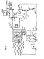
- FIG. 1 illustrates a system used in an embodiment of the invention.
- the polymerization is carried out in a loop reactor 1.
- the loop reactor 1 may be equipped with more legs, desirably eight or more legs, desirable between 8 and 20, more desirable between 8 and 16, most desirable with 12 legs.
- the polymerization slurry is directionally circulated throughout the loop reactor 1 as illustrated by arrows A-D by one or more pumps, such as axial flow pumps, 2A and 2B.
- the loop reactor 1 is equipped with multiple pumps wherein each pump is dedicated to an even number of legs, such as for example, four legs, six legs, eight legs, etc.
- Diluent comonomer and monomer are introduced into the loop reactor 1 from the diluent storage vessel 40, the comonomer storage vessel 41, and the monomer source 42 through their respective treater beds 37, 38, and 39 through conduits 5, 4 and 3, respectively, connected to conduit 6.
- Catalyst is added to the loop reactor 1 through one or more catalyst feed systems 7A and 7B.. Normally, catalyst is introduced in a hydrocarbon diluent.
- Polymerization slurry may be removed from the loop reactor by continuous discharge through a discharge conduit 8A.
- the loop reactor 1 may be equipped with one or more discharge conduits 8A.
- the discharge conduit(s) 8A may be operated in a continuous or discontinuous mode, but desirably a continuous mode.
- the discharge conduit 8A extends for a distance through a portion of the wall of the loop reactor 1 and into the circulating polymerization slurry.
- the discharge conduit 8A may remove polymerization effluent from the circulating polymerization slurry over an area defined from near or adjacent the inside wall of the loop reactor 1 to a distance extending into the circulating polymerization slurry. In this way, a higher weight percentage of polymer solids may be formed within the conduit 8A and ultimately removed from the loop reactor 1 than the weight percentage of polymer solids within the otherwise circulating polymerization slurry.
- the polymerization effluent passes from the discharge conduit 8A to the discharge valve 8B to a conduit 9 which is provided with a line heater 10 and into the first flash tank 11 which separate vaporized liquid medium from polymer slurry/solids.
- Conduit 9 has an indirect heat exchange means such as a flash line heater 10.
- Vaporized liquid medium comprising diluent and unreacted monomers exit the first flash tank 11 via transfer conduit 12 through which it is passed into a separator, such as a cyclone, illustrated by reference number 13 which separates entrained polymer solids from the vapor.
- a separator such as a cyclone, illustrated by reference number 13 which separates entrained polymer solids from the vapor.
- Polymer solids separated by the cyclone 13 are passed via conduit 14 through a dual valving assembly 14A designed to maintain a pressure seal below cyclone 13 to a lower pressure second flash tank 15.
- the polymer solids in the lower pressure second flash tank 15 are passed via a conduit 27 to a conventional dryer 28.
- the vapor exiting the secondary cyclone 21, after filtration in a filter unit 29, is passed by a conduit 30 to a compressor 31, and the compressed vapors are passed through a conduit 32 to a condenser 33 where vapor is condensed and the condensate is passed through conduit 34 to storage vessel 35,
- the condensed liquid medium in the storage vessel 35 is typically vented overhead for removal of light-end contaminants.
- the inert diluent can be returned to the process through a treater bed 37 to remove catalyst poisons or distilled in unit 36 for more complete removal of light-ends and then returned to the process through a treater bed.
- Fig 2 shows an embodiment in accordance with the present invention.
- discharge conduit 8C extends through a portion, preferably a lower portion, of a wall 310 of the loop reactor 1.
- Wall 310 is part of the outside wall of the loop reactor ( Fig 4 ).
- "outside wall” means that portion of the reactor wall towards which the solids in the loop reactor slurry tend to flow, by centrifugal force, when the slurry travels through a bend in the loop reactor.
- the illustrated "outside wall” is the lower portion 310 of the reactor wall.
- At least a portion of the discharge conduit 8C is curved along its longitudinal axis inside the loop reactor.
- the opening 325 preferably, located at the end of the curved conduit inside the loop reactor is substantially facing the flow of the circulating slurry 318.
- the discharge conduit is located within a middle portion of the curved portion of the loop reactor, more preferably substantially at the middle of the curved portion, most preferably in a lower leg of the reactor.
- the curved portion 310 of the loop reactor comprises a 20 to 270 degree bend, preferably a 80 to 200 degree bend, more preferably a 90 to 180 degree bend, and most preferably a 180 degree bend.
- the preferred bend can be 80 to 180 degree bend.
- the discharge conduit 8C is located substantially at the bottom of a 180 degree bend of the loop reactor 1.
- a 180 degree bend of the loop reactor Such an embodiment is illustrated schematically in Figure 3 .
- at least one bottom leg 328 of the reactor has a bend of about 180 degrees.
- the lower leg of the loop reactor is substantially "U" shaped.
- discharge conduit 8C is preferably located substantially in a central portion of generally U shaped bottom leg 328 and extends through the bottom wall 310 of the reactor 1.
- the opening 325 is located inside the loop reactor in any position but preferably close to the outside wall in the lower leg of the loop reactor so as to capture a higher concentration of solids than the average concentration of solids in the loop reactor.
- the centrifugal force of the circulating flow cause a higher concentration of solids in the lower portion of the cross-section of the lower leg.
- the average concentration of solids in the loop reactor is about 55 wt.% and the captured solids concentration is above 57 wt.%, preferably above 60 wt.%, more preferably above 65 wt.%.
- the opening 325 is located closer to the outside wall 310 of the loop reactor than to the inside wall 330 of the loop reactor.
- the opening is located closer to the outside wall. 310 of the loop reactor than to the center 331 of the loop reactor. More preferably, the opening is closely adjacent to the outside wall of the loop reactor. Most preferably, the opening touches the outside wall of the loop reactor.
- the section of the discharge conduit 8C inside the loop reactor is bent in a curve towards the flow of the slurry 318 of the loop reactor.
- the discharge conduit has a diameter less than that of the loop reactor legs to avoid interference with the flow of the polymerization slurry circulation inside the loop reactor.
- the discharge conduit has a diameter 5-40% of the diameter of loop reactor, more preferably 7-25%, and most preferably 8-15%.
- the diameter of the loop reactor is measured in the immediate area of the opening of the discharge conduit
- the discharge conduit is a pipe haying a substantially circular transverse cross section of about 2-inch diameter while the diameter of the loop reactor in the immediate area is about 20 inches.
- the discharge conduit 8C is curved substantially towards the flow of the circulating slurry.
- the curve is from about 45 degrees to about 135 degrees. More preferably, the curve is from about 75 degrees to about 135 degrees.
- the face of the opening at the end of the discharge conduit defines a plane 329 which intersects an outside wall of the loop reactor at a tangent line which is substantially perpendicular to the plane.
- the conventional loop reactor settling legs which are designed to maximize polymer solids concentration prior to discharge, can be replaced with a continuous discharge line, which simplifies the system mechanically, reduces capital cost, improves safety, reduces maintenance and improves reactor control.
- Settling legs require routine maintenance due to their plugging tendency and can form material which plugs downstream polymer handling equipment.
- Maximum loop reactor ethylene concentration is limited by settling legs due to the tendency for polymer to grow in the legs at elevated ethylene concentrations between discharges and therefore plug the leg. Continuous discharge eliminates this tendency.
- Another advantage of continuous discharge is better response to a sudden drop in reactor pressure, which can happen if ethylene flow is quickly reduced. Under this condition, settling legs will stop discharging and can plug with polymer within minutes.
Landscapes
- Chemical & Material Sciences (AREA)
- Chemical Kinetics & Catalysis (AREA)
- Organic Chemistry (AREA)
- Dispersion Chemistry (AREA)
- Health & Medical Sciences (AREA)
- Medicinal Chemistry (AREA)
- Polymers & Plastics (AREA)
- Polymerisation Methods In General (AREA)
- Addition Polymer Or Copolymer, Post-Treatments, Or Chemical Modifications (AREA)
- Transition And Organic Metals Composition Catalysts For Addition Polymerization (AREA)
Claims (11)
- Ein Verfahren zum Einfangen eines höheren Gewichtsprozentsatzes von polymeren Feststoffen aus einer zirkulierenden Suspension in einem Schlaufenreaktor als der Gewichtsprozentsatz von polymeren Feststoffen in der zirkulierenden Suspension, wobei das Verfahren in einem Schlaufenreaktor für Suspensionspolymerisation durchgeführt wird, der einen Strom einer Polymerisationssuspension darin einschließt und der folgendes umfasst:eine Abgabeleitung, die sich mit einem Abstand in den Schlaufenreaktor erstreckt;wobei die Leitung eine Längsachse und eine Öffnung im Inneren des Schlaufenreaktors aufweist, wobei sich die Öffnung näher zu der Außenwand des Schlaufenreaktors als zu der Innenwand des Schlaufenreaktors befindet;mindestens ein Teil der Leitung entlang ihrer Längsachse im Inneren des Schlaufenreaktors gekrümmt ist; unddie Öffnung im Wesentlichen dem Strom der Suspension gegenüber steht,und wobei das Verfahren den Schritt der Abgabe von polymeren Feststoffen aus dem Schlaufenreaktor über einen Abschnitt der Leitung umfasst, der sich aus dem Schlaufenreaktor nach außen erstreckt.
- Das Verfahren nach Anspruch 1, wobei sich die Abgabeleitung in einem gekrümmten Abschnitt des Schlaufenreaktors, vorzugsweise einem Schenkel des Schlaufenreaktors befindet.
- Das Verfahren nach Anspruch 2, wobei sich die Abgabeleitung in einem mittleren Abschnitt des gekrümmten Abschnitts des Schlaufenreaktors befindet und sich vorzugsweise im Wesentlichen an der Mitte des gekrümmten Abschnitts des Schlaufenreaktors befindet.
- Das Verfahren nach Anspruch 2 oder Anspruch 3, wobei der gekrümmte Abschnitt eine Krümmung von 20 bis 270 Grad, vorzugsweise eine Krümmung von 80 bis 200 Grad und insbesondere eine Krümmung von 90 bis 180 Grad umfasst.
- Das Verfahren nach einem der Ansprüche 2 bis 4, wobei der gekrümmte Abschnitt eine Krümmung von 180 Grad umfasst.
- Das Verfahren nach Anspruch 1, wobei die Abgabeleitung entlang ihrer Längsachse von 45 Grad bis 135 Grad, vorzugsweise von 75 Grad bis 135 Grad gekrümmt ist.
- Das Verfahren nach einem der Ansprüche 1 bis 5, wobei die Stirnfläche der Öffnung eine Ebene definiert, die eine Außenwand des Schlaufenreaktors an einer Tangente schneidet, die im Wesentlichen senkrecht zu der Ebene liegt.
- Das Verfahren nach einem der Ansprüche 1 bis 3, wobei die Abgabeleitung einen Durchmesser aufweist, der 5-40 % des Innendurchmessers des Schlaufenreaktors, vorzugsweise 7-25 % des Innendurchmessers des Schlaufenreaktors und insbesondere 8-15 % des Innendurchmessers des Schlaufenreaktors beträgt.
- Das Verfahren nach Anspruch 1, wobei sich die Öffnung näher an einer Außenwand des Schlaufenreaktors als zu der Mitte des Schlaufenreaktors befindet.
- Das Verfahren nach Anspruch 9, wobei sich die Öffnung eng benachbart zu der Außenwand des Schlaufenreaktors befindet und vorzugsweise die Außenwand des Schlaufenreaktors berührt.
- Das Verfahren nach Anspruch 1, wobei
sich die Abgabeleitung im Wesentlichen an der Mitte eines gekrümmten Abschnitts des Schlaufenreaktors befindet;
der gekrümmte Abschnitt des Schlaufenreaktors einen Schenkel des Schlaufenreaktors umfasst;
der gekrümmte Abschnitt des Schlaufenreaktors eine Krümmung von 180 Grad umfasst;
die Abgabeleitung entlang ihrer Längsachse mehr als etwa 75 Grad, jedoch weniger als etwa 135 Grad gekrümmt ist;
die Stirnfläche der Öffnung eine Ebene definiert, die eine Außenwand des Schlaufenreaktors an einer Tangente schneidet, die im Wesentlichen senkrecht zu der Ebene liegt;
die Abgabeleitung einen Durchmesser aufweist, der etwa 8-15 % des Innendurchmessers des Schlaufenreaktors beträgt; und
sich die Öffnung näher zu der Außenwand als zu der Mitte des Schlaufenreaktors befindet.
Applications Claiming Priority (1)
| Application Number | Priority Date | Filing Date | Title |
|---|---|---|---|
| PCT/US2001/043708 WO2003039739A1 (en) | 2001-11-06 | 2001-11-06 | Continuous removal of polymerization slurry |
Publications (2)
| Publication Number | Publication Date |
|---|---|
| EP1444035A1 EP1444035A1 (de) | 2004-08-11 |
| EP1444035B1 true EP1444035B1 (de) | 2010-07-07 |
Family
ID=21743005
Family Applications (1)
| Application Number | Title | Priority Date | Filing Date |
|---|---|---|---|
| EP01989743A Expired - Lifetime EP1444035B1 (de) | 2001-11-06 | 2001-11-06 | Kontinuierliches entfernen von suspension aus polymerisationsverfahren |
Country Status (5)
| Country | Link |
|---|---|
| EP (1) | EP1444035B1 (de) |
| AT (1) | ATE473047T1 (de) |
| DE (1) | DE60142531D1 (de) |
| ES (1) | ES2348659T3 (de) |
| WO (1) | WO2003039739A1 (de) |
Cited By (1)
| Publication number | Priority date | Publication date | Assignee | Title |
|---|---|---|---|---|
| CN107249727A (zh) * | 2015-02-06 | 2017-10-13 | 阿朗新科德国有限责任公司 | 用于多相聚合的管式反应器和方法 |
Families Citing this family (6)
| Publication number | Priority date | Publication date | Assignee | Title |
|---|---|---|---|---|
| US7268194B2 (en) | 1998-03-20 | 2007-09-11 | Exxonmobil Chemical Patents Inc. | Continuous slurry polymerization process and apparatus |
| CA2476701A1 (en) * | 2002-02-19 | 2003-08-28 | James A. Kendrick | Continuous slurry polymerization process using a loop reactor |
| GB0426058D0 (en) | 2004-11-26 | 2004-12-29 | Solvay | Chemical process |
| GB0426057D0 (en) | 2004-11-26 | 2004-12-29 | Solvay | Chemical process |
| GB0426059D0 (en) | 2004-11-26 | 2004-12-29 | Solvay | Chemical process |
| US7547750B2 (en) * | 2005-10-05 | 2009-06-16 | Chevron Phillips Chemical Company Lp | Apparatus and method for removing polymer solids from slurry loop reactor |
Family Cites Families (5)
| Publication number | Priority date | Publication date | Assignee | Title |
|---|---|---|---|---|
| US1693786A (en) * | 1924-09-17 | 1928-12-04 | Krystal As | Process for the crystallization of solid substances in a coarse granular form from solutions |
| US3203766A (en) * | 1961-07-06 | 1965-08-31 | Phillips Petroleum Co | Apparatus for the recovery of solids from pressure vessels |
| US3293000A (en) * | 1962-10-05 | 1966-12-20 | Phillips Petroleum Co | Withdrawal of solids from a flowing stream comprising a slurry of same |
| US6239235B1 (en) * | 1997-07-15 | 2001-05-29 | Phillips Petroleum Company | High solids slurry polymerization |
| HK1048327A1 (zh) * | 1999-07-15 | 2003-03-28 | 菲利浦石油公司 | 以开槽方式引出悬浮体 |
-
2001
- 2001-11-06 EP EP01989743A patent/EP1444035B1/de not_active Expired - Lifetime
- 2001-11-06 DE DE60142531T patent/DE60142531D1/de not_active Expired - Lifetime
- 2001-11-06 WO PCT/US2001/043708 patent/WO2003039739A1/en not_active Ceased
- 2001-11-06 ES ES01989743T patent/ES2348659T3/es not_active Expired - Lifetime
- 2001-11-06 AT AT01989743T patent/ATE473047T1/de not_active IP Right Cessation
Cited By (1)
| Publication number | Priority date | Publication date | Assignee | Title |
|---|---|---|---|---|
| CN107249727A (zh) * | 2015-02-06 | 2017-10-13 | 阿朗新科德国有限责任公司 | 用于多相聚合的管式反应器和方法 |
Also Published As
| Publication number | Publication date |
|---|---|
| DE60142531D1 (de) | 2010-08-19 |
| EP1444035A1 (de) | 2004-08-11 |
| ATE473047T1 (de) | 2010-07-15 |
| WO2003039739A1 (en) | 2003-05-15 |
| ES2348659T3 (es) | 2010-12-10 |
Similar Documents
| Publication | Publication Date | Title |
|---|---|---|
| EP1437174B1 (de) | Kontiuierliches Entfernen flüchtiger Bestandteile aus Suspensionspolymerisation | |
| EP1064086B1 (de) | Kontinuierliches entfernen flüchtiger bestandteile aus suspensionspolymerisation | |
| US6926868B2 (en) | Continuous slurry polymerization volatile removal | |
| US6281300B1 (en) | Continuous slurry polymerization volatile removal | |
| US7575724B2 (en) | Continuous slurry polymerization apparatus | |
| EP2263793B1 (de) | Verfahren für einen schleifenpolymerisierungsreaktor | |
| US6800698B2 (en) | Continuous slurry polymerization volatile removal | |
| EP1444035B1 (de) | Kontinuierliches entfernen von suspension aus polymerisationsverfahren | |
| EP1344563B1 (de) | Kontinuierliches Entfernen flüchtiger Bestandteile aus Suspensionspolymerisation | |
| EP1444273B1 (de) | Kontinuierliches entfernen flüchtiger bestandteile aus suspensionspolymerisation |
Legal Events
| Date | Code | Title | Description |
|---|---|---|---|
| PUAI | Public reference made under article 153(3) epc to a published international application that has entered the european phase |
Free format text: ORIGINAL CODE: 0009012 |
|
| 17P | Request for examination filed |
Effective date: 20040604 |
|
| AK | Designated contracting states |
Kind code of ref document: A1 Designated state(s): AT BE CH CY DE DK ES FI FR GB GR IE IT LI LU MC NL PT SE TR |
|
| AX | Request for extension of the european patent |
Extension state: AL LT LV MK RO SI |
|
| RAP1 | Party data changed (applicant data changed or rights of an application transferred) |
Owner name: CHEVRON PHILLIPS CHEMICAL COMPANY LP |
|
| 17Q | First examination report despatched |
Effective date: 20080509 |
|
| GRAP | Despatch of communication of intention to grant a patent |
Free format text: ORIGINAL CODE: EPIDOSNIGR1 |
|
| GRAS | Grant fee paid |
Free format text: ORIGINAL CODE: EPIDOSNIGR3 |
|
| GRAA | (expected) grant |
Free format text: ORIGINAL CODE: 0009210 |
|
| AK | Designated contracting states |
Kind code of ref document: B1 Designated state(s): AT BE CH CY DE DK ES FI FR GB GR IE IT LI LU MC NL PT SE TR |
|
| REG | Reference to a national code |
Ref country code: GB Ref legal event code: FG4D |
|
| REG | Reference to a national code |
Ref country code: CH Ref legal event code: EP |
|
| REG | Reference to a national code |
Ref country code: IE Ref legal event code: FG4D |
|
| REF | Corresponds to: |
Ref document number: 60142531 Country of ref document: DE Date of ref document: 20100819 Kind code of ref document: P |
|
| REG | Reference to a national code |
Ref country code: NL Ref legal event code: VDEP Effective date: 20100707 |
|
| REG | Reference to a national code |
Ref country code: ES Ref legal event code: FG2A Effective date: 20101126 |
|
| PG25 | Lapsed in a contracting state [announced via postgrant information from national office to epo] |
Ref country code: FI Free format text: LAPSE BECAUSE OF FAILURE TO SUBMIT A TRANSLATION OF THE DESCRIPTION OR TO PAY THE FEE WITHIN THE PRESCRIBED TIME-LIMIT Effective date: 20100707 Ref country code: AT Free format text: LAPSE BECAUSE OF FAILURE TO SUBMIT A TRANSLATION OF THE DESCRIPTION OR TO PAY THE FEE WITHIN THE PRESCRIBED TIME-LIMIT Effective date: 20100707 Ref country code: NL Free format text: LAPSE BECAUSE OF FAILURE TO SUBMIT A TRANSLATION OF THE DESCRIPTION OR TO PAY THE FEE WITHIN THE PRESCRIBED TIME-LIMIT Effective date: 20100707 |
|
| PG25 | Lapsed in a contracting state [announced via postgrant information from national office to epo] |
Ref country code: CY Free format text: LAPSE BECAUSE OF FAILURE TO SUBMIT A TRANSLATION OF THE DESCRIPTION OR TO PAY THE FEE WITHIN THE PRESCRIBED TIME-LIMIT Effective date: 20100707 Ref country code: PT Free format text: LAPSE BECAUSE OF FAILURE TO SUBMIT A TRANSLATION OF THE DESCRIPTION OR TO PAY THE FEE WITHIN THE PRESCRIBED TIME-LIMIT Effective date: 20101108 |
|
| PG25 | Lapsed in a contracting state [announced via postgrant information from national office to epo] |
Ref country code: GR Free format text: LAPSE BECAUSE OF FAILURE TO SUBMIT A TRANSLATION OF THE DESCRIPTION OR TO PAY THE FEE WITHIN THE PRESCRIBED TIME-LIMIT Effective date: 20101008 Ref country code: SE Free format text: LAPSE BECAUSE OF FAILURE TO SUBMIT A TRANSLATION OF THE DESCRIPTION OR TO PAY THE FEE WITHIN THE PRESCRIBED TIME-LIMIT Effective date: 20100707 |
|
| PG25 | Lapsed in a contracting state [announced via postgrant information from national office to epo] |
Ref country code: DK Free format text: LAPSE BECAUSE OF FAILURE TO SUBMIT A TRANSLATION OF THE DESCRIPTION OR TO PAY THE FEE WITHIN THE PRESCRIBED TIME-LIMIT Effective date: 20100707 |
|
| PLBE | No opposition filed within time limit |
Free format text: ORIGINAL CODE: 0009261 |
|
| STAA | Information on the status of an ep patent application or granted ep patent |
Free format text: STATUS: NO OPPOSITION FILED WITHIN TIME LIMIT |
|
| PG25 | Lapsed in a contracting state [announced via postgrant information from national office to epo] |
Ref country code: IT Free format text: LAPSE BECAUSE OF FAILURE TO SUBMIT A TRANSLATION OF THE DESCRIPTION OR TO PAY THE FEE WITHIN THE PRESCRIBED TIME-LIMIT Effective date: 20100707 |
|
| 26N | No opposition filed |
Effective date: 20110408 |
|
| PG25 | Lapsed in a contracting state [announced via postgrant information from national office to epo] |
Ref country code: MC Free format text: LAPSE BECAUSE OF NON-PAYMENT OF DUE FEES Effective date: 20101130 |
|
| REG | Reference to a national code |
Ref country code: CH Ref legal event code: PL |
|
| REG | Reference to a national code |
Ref country code: DE Ref legal event code: R097 Ref document number: 60142531 Country of ref document: DE Effective date: 20110408 |
|
| GBPC | Gb: european patent ceased through non-payment of renewal fee |
Effective date: 20101106 |
|
| PG25 | Lapsed in a contracting state [announced via postgrant information from national office to epo] |
Ref country code: CH Free format text: LAPSE BECAUSE OF NON-PAYMENT OF DUE FEES Effective date: 20101130 Ref country code: LI Free format text: LAPSE BECAUSE OF NON-PAYMENT OF DUE FEES Effective date: 20101130 |
|
| REG | Reference to a national code |
Ref country code: FR Ref legal event code: ST Effective date: 20110801 |
|
| REG | Reference to a national code |
Ref country code: DE Ref legal event code: R119 Ref document number: 60142531 Country of ref document: DE Effective date: 20110601 Ref country code: DE Ref legal event code: R119 Ref document number: 60142531 Country of ref document: DE Effective date: 20110531 |
|
| PG25 | Lapsed in a contracting state [announced via postgrant information from national office to epo] |
Ref country code: IE Free format text: LAPSE BECAUSE OF NON-PAYMENT OF DUE FEES Effective date: 20101106 Ref country code: FR Free format text: LAPSE BECAUSE OF NON-PAYMENT OF DUE FEES Effective date: 20101130 |
|
| PG25 | Lapsed in a contracting state [announced via postgrant information from national office to epo] |
Ref country code: GB Free format text: LAPSE BECAUSE OF NON-PAYMENT OF DUE FEES Effective date: 20101106 |
|
| PG25 | Lapsed in a contracting state [announced via postgrant information from national office to epo] |
Ref country code: LU Free format text: LAPSE BECAUSE OF NON-PAYMENT OF DUE FEES Effective date: 20101106 |
|
| PG25 | Lapsed in a contracting state [announced via postgrant information from national office to epo] |
Ref country code: TR Free format text: LAPSE BECAUSE OF FAILURE TO SUBMIT A TRANSLATION OF THE DESCRIPTION OR TO PAY THE FEE WITHIN THE PRESCRIBED TIME-LIMIT Effective date: 20100707 |
|
| PG25 | Lapsed in a contracting state [announced via postgrant information from national office to epo] |
Ref country code: DE Free format text: LAPSE BECAUSE OF NON-PAYMENT OF DUE FEES Effective date: 20110531 |
|
| PGFP | Annual fee paid to national office [announced via postgrant information from national office to epo] |
Ref country code: ES Payment date: 20201201 Year of fee payment: 20 |
|
| PGFP | Annual fee paid to national office [announced via postgrant information from national office to epo] |
Ref country code: BE Payment date: 20201023 Year of fee payment: 20 |
|
| REG | Reference to a national code |
Ref country code: BE Ref legal event code: MK Effective date: 20211106 |
|
| REG | Reference to a national code |
Ref country code: ES Ref legal event code: FD2A Effective date: 20220225 |
|
| PG25 | Lapsed in a contracting state [announced via postgrant information from national office to epo] |
Ref country code: ES Free format text: LAPSE BECAUSE OF EXPIRATION OF PROTECTION Effective date: 20211107 |