EP1444042B1 - Verfahren zur förderung einer flüssigkeit in einer kapillare und fluidisches mikrosystem - Google Patents
Verfahren zur förderung einer flüssigkeit in einer kapillare und fluidisches mikrosystem Download PDFInfo
- Publication number
- EP1444042B1 EP1444042B1 EP02799424A EP02799424A EP1444042B1 EP 1444042 B1 EP1444042 B1 EP 1444042B1 EP 02799424 A EP02799424 A EP 02799424A EP 02799424 A EP02799424 A EP 02799424A EP 1444042 B1 EP1444042 B1 EP 1444042B1
- Authority
- EP
- European Patent Office
- Prior art keywords
- ferrofluid
- fluid
- capillary channel
- train
- slug
- Prior art date
- Legal status (The legal status is an assumption and is not a legal conclusion. Google has not performed a legal analysis and makes no representation as to the accuracy of the status listed.)
- Expired - Lifetime
Links
- 239000012530 fluid Substances 0.000 title claims abstract description 87
- 238000000034 method Methods 0.000 title claims abstract description 23
- 239000011554 ferrofluid Substances 0.000 claims abstract description 132
- 230000005291 magnetic effect Effects 0.000 claims abstract description 32
- 239000007788 liquid Substances 0.000 claims abstract description 28
- 238000006073 displacement reaction Methods 0.000 claims abstract description 15
- 230000009471 action Effects 0.000 claims abstract description 4
- 239000012491 analyte Substances 0.000 claims abstract 18
- 230000002209 hydrophobic effect Effects 0.000 claims description 7
- 239000000356 contaminant Substances 0.000 claims description 4
- 238000001514 detection method Methods 0.000 claims description 2
- 238000000338 in vitro Methods 0.000 claims description 2
- 241000237858 Gastropoda Species 0.000 claims 2
- 239000003921 oil Substances 0.000 description 21
- XLYOFNOQVPJJNP-UHFFFAOYSA-N water Substances O XLYOFNOQVPJJNP-UHFFFAOYSA-N 0.000 description 6
- 238000011109 contamination Methods 0.000 description 5
- 239000000463 material Substances 0.000 description 5
- 238000006243 chemical reaction Methods 0.000 description 4
- 239000003153 chemical reaction reagent Substances 0.000 description 4
- 238000002032 lab-on-a-chip Methods 0.000 description 4
- 239000002245 particle Substances 0.000 description 4
- 238000003752 polymerase chain reaction Methods 0.000 description 4
- 239000004094 surface-active agent Substances 0.000 description 4
- 229920006362 Teflon® Polymers 0.000 description 3
- 239000007864 aqueous solution Substances 0.000 description 3
- 230000001276 controlling effect Effects 0.000 description 3
- 238000005516 engineering process Methods 0.000 description 3
- 239000011521 glass Substances 0.000 description 3
- 150000002500 ions Chemical class 0.000 description 3
- 239000006249 magnetic particle Substances 0.000 description 3
- 239000002480 mineral oil Substances 0.000 description 3
- 235000010446 mineral oil Nutrition 0.000 description 3
- 239000000243 solution Substances 0.000 description 3
- 239000000126 substance Substances 0.000 description 3
- UQSXHKLRYXJYBZ-UHFFFAOYSA-N Iron oxide Chemical compound [Fe]=O UQSXHKLRYXJYBZ-UHFFFAOYSA-N 0.000 description 2
- 239000004809 Teflon Substances 0.000 description 2
- 230000003213 activating effect Effects 0.000 description 2
- 230000003321 amplification Effects 0.000 description 2
- 238000004458 analytical method Methods 0.000 description 2
- 239000008346 aqueous phase Substances 0.000 description 2
- 230000008901 benefit Effects 0.000 description 2
- 230000000903 blocking effect Effects 0.000 description 2
- SNRUBQQJIBEYMU-UHFFFAOYSA-N dodecane Chemical compound CCCCCCCCCCCC SNRUBQQJIBEYMU-UHFFFAOYSA-N 0.000 description 2
- 239000010408 film Substances 0.000 description 2
- JEIPFZHSYJVQDO-UHFFFAOYSA-N iron(III) oxide Inorganic materials O=[Fe]O[Fe]=O JEIPFZHSYJVQDO-UHFFFAOYSA-N 0.000 description 2
- 238000003199 nucleic acid amplification method Methods 0.000 description 2
- 230000008569 process Effects 0.000 description 2
- 238000004088 simulation Methods 0.000 description 2
- 238000009736 wetting Methods 0.000 description 2
- RBTBFTRPCNLSDE-UHFFFAOYSA-N 3,7-bis(dimethylamino)phenothiazin-5-ium Chemical compound C1=CC(N(C)C)=CC2=[S+]C3=CC(N(C)C)=CC=C3N=C21 RBTBFTRPCNLSDE-UHFFFAOYSA-N 0.000 description 1
- VYPSYNLAJGMNEJ-UHFFFAOYSA-N Silicium dioxide Chemical compound O=[Si]=O VYPSYNLAJGMNEJ-UHFFFAOYSA-N 0.000 description 1
- 229920006355 Tefzel Polymers 0.000 description 1
- QJVKUMXDEUEQLH-UHFFFAOYSA-N [B].[Fe].[Nd] Chemical compound [B].[Fe].[Nd] QJVKUMXDEUEQLH-UHFFFAOYSA-N 0.000 description 1
- 239000002250 absorbent Substances 0.000 description 1
- 230000002745 absorbent Effects 0.000 description 1
- 238000003556 assay Methods 0.000 description 1
- 239000013060 biological fluid Substances 0.000 description 1
- 238000001311 chemical methods and process Methods 0.000 description 1
- 239000011248 coating agent Substances 0.000 description 1
- 238000000576 coating method Methods 0.000 description 1
- 239000000470 constituent Substances 0.000 description 1
- 230000008878 coupling Effects 0.000 description 1
- 238000010168 coupling process Methods 0.000 description 1
- 238000005859 coupling reaction Methods 0.000 description 1
- 238000011161 development Methods 0.000 description 1
- 238000001962 electrophoresis Methods 0.000 description 1
- QHSJIZLJUFMIFP-UHFFFAOYSA-N ethene;1,1,2,2-tetrafluoroethene Chemical compound C=C.FC(F)=C(F)F QHSJIZLJUFMIFP-UHFFFAOYSA-N 0.000 description 1
- 238000002474 experimental method Methods 0.000 description 1
- 230000005294 ferromagnetic effect Effects 0.000 description 1
- 239000005350 fused silica glass Substances 0.000 description 1
- 230000005661 hydrophobic surface Effects 0.000 description 1
- 230000002706 hydrostatic effect Effects 0.000 description 1
- 238000002347 injection Methods 0.000 description 1
- 239000007924 injection Substances 0.000 description 1
- 229910052500 inorganic mineral Inorganic materials 0.000 description 1
- SZVJSHCCFOBDDC-UHFFFAOYSA-N iron(II,III) oxide Inorganic materials O=[Fe]O[Fe]O[Fe]=O SZVJSHCCFOBDDC-UHFFFAOYSA-N 0.000 description 1
- 238000009533 lab test Methods 0.000 description 1
- 239000011553 magnetic fluid Substances 0.000 description 1
- 229960000907 methylthioninium chloride Drugs 0.000 description 1
- 230000002906 microbiologic effect Effects 0.000 description 1
- 239000011707 mineral Substances 0.000 description 1
- 229910001172 neodymium magnet Inorganic materials 0.000 description 1
- NHNBFGGVMKEFGY-UHFFFAOYSA-N nitrate group Chemical group [N+](=O)([O-])[O-] NHNBFGGVMKEFGY-UHFFFAOYSA-N 0.000 description 1
- 150000002894 organic compounds Chemical class 0.000 description 1
- 239000012071 phase Substances 0.000 description 1
- 239000002243 precursor Substances 0.000 description 1
- 238000012545 processing Methods 0.000 description 1
- 230000001105 regulatory effect Effects 0.000 description 1
- 238000000926 separation method Methods 0.000 description 1
- 238000002444 silanisation Methods 0.000 description 1
- 230000003068 static effect Effects 0.000 description 1
- 239000010409 thin film Substances 0.000 description 1
- 238000011144 upstream manufacturing Methods 0.000 description 1
Images



Classifications
-
- B—PERFORMING OPERATIONS; TRANSPORTING
- B01—PHYSICAL OR CHEMICAL PROCESSES OR APPARATUS IN GENERAL
- B01L—CHEMICAL OR PHYSICAL LABORATORY APPARATUS FOR GENERAL USE
- B01L3/00—Containers or dishes for laboratory use, e.g. laboratory glassware; Droppers
- B01L3/50—Containers for the purpose of retaining a material to be analysed, e.g. test tubes
- B01L3/502—Containers for the purpose of retaining a material to be analysed, e.g. test tubes with fluid transport, e.g. in multi-compartment structures
- B01L3/5027—Containers for the purpose of retaining a material to be analysed, e.g. test tubes with fluid transport, e.g. in multi-compartment structures by integrated microfluidic structures, i.e. dimensions of channels and chambers are such that surface tension forces are important, e.g. lab-on-a-chip
- B01L3/502769—Containers for the purpose of retaining a material to be analysed, e.g. test tubes with fluid transport, e.g. in multi-compartment structures by integrated microfluidic structures, i.e. dimensions of channels and chambers are such that surface tension forces are important, e.g. lab-on-a-chip characterised by multiphase flow arrangements
- B01L3/502784—Containers for the purpose of retaining a material to be analysed, e.g. test tubes with fluid transport, e.g. in multi-compartment structures by integrated microfluidic structures, i.e. dimensions of channels and chambers are such that surface tension forces are important, e.g. lab-on-a-chip characterised by multiphase flow arrangements specially adapted for droplet or plug flow, e.g. digital microfluidics
-
- B—PERFORMING OPERATIONS; TRANSPORTING
- B01—PHYSICAL OR CHEMICAL PROCESSES OR APPARATUS IN GENERAL
- B01L—CHEMICAL OR PHYSICAL LABORATORY APPARATUS FOR GENERAL USE
- B01L2200/00—Solutions for specific problems relating to chemical or physical laboratory apparatus
- B01L2200/06—Fluid handling related problems
- B01L2200/0673—Handling of plugs of fluid surrounded by immiscible fluid
-
- B—PERFORMING OPERATIONS; TRANSPORTING
- B01—PHYSICAL OR CHEMICAL PROCESSES OR APPARATUS IN GENERAL
- B01L—CHEMICAL OR PHYSICAL LABORATORY APPARATUS FOR GENERAL USE
- B01L2400/00—Moving or stopping fluids
- B01L2400/04—Moving fluids with specific forces or mechanical means
- B01L2400/0403—Moving fluids with specific forces or mechanical means specific forces
- B01L2400/043—Moving fluids with specific forces or mechanical means specific forces magnetic forces
-
- H—ELECTRICITY
- H01—ELECTRIC ELEMENTS
- H01F—MAGNETS; INDUCTANCES; TRANSFORMERS; SELECTION OF MATERIALS FOR THEIR MAGNETIC PROPERTIES
- H01F1/00—Magnets or magnetic bodies characterised by the magnetic materials therefor; Selection of materials for their magnetic properties
- H01F1/44—Magnets or magnetic bodies characterised by the magnetic materials therefor; Selection of materials for their magnetic properties of magnetic liquids, e.g. ferrofluids
- H01F1/447—Magnets or magnetic bodies characterised by the magnetic materials therefor; Selection of materials for their magnetic properties of magnetic liquids, e.g. ferrofluids characterised by magnetoviscosity, e.g. magnetorheological, magnetothixotropic, magnetodilatant liquids
-
- H—ELECTRICITY
- H01—ELECTRIC ELEMENTS
- H01F—MAGNETS; INDUCTANCES; TRANSFORMERS; SELECTION OF MATERIALS FOR THEIR MAGNETIC PROPERTIES
- H01F21/00—Variable inductances or transformers of the signal type
- H01F21/02—Variable inductances or transformers of the signal type continuously variable, e.g. variometers
- H01F21/06—Variable inductances or transformers of the signal type continuously variable, e.g. variometers by movement of core or part of core relative to the windings as a whole
Definitions
- the present invention relates to a method of moving a fluid of interest in a capillary and a fluid microsystem.
- microfluidics including fluidic microsystems. It makes it possible to carry out high-throughput biological or chemical processes.
- the present invention can be combined with other functions to form a more complete and more accurate system of biological analysis.
- variable surface states to regulate flows, but they impose constraints on the physicochemical properties of the fluids to be transported and a precise treatment of the surfaces. It is also possible to use bubble generation to regulate flow rates inside capillaries. Finally, mechanical systems for regulating the hydrostatic pressure also exist, implanted upstream of the microcircuits or downstream, for example by placing a wick made of an absorbent material.
- the present invention also provides a fluidic microsystem for displacing a fluid of interest comprising on the one hand a capillary in which at least one ferrofluid train is placed and, on the other hand, outside said capillary, a magnetic system for producing a magnetic field for controlling the movement of the ferrofluid train in the capillary, said ferrofluid train comprising a ferrofluid plug and, placed at at least one of the two ends of the ferrofluid plug and secured thereto, a plug of liquid immiscible with the ferrofluid and the fluid of interest.
- fluid of interest any liquid or gaseous fluid that is necessary to move in a capillary, for example in analytical microsystems.
- the fluid of interest may be, for example, a chemical reagent, a biological liquid, an aqueous solution, etc.
- Plug means a volume of fluid in the capillary and forming by capillarity a "cylinder" conforming to the shape of the inner wall of the capillary.
- the fluid placed in the capillary forms a plug when it occupies, over a length that depends on the volume of this fluid, the entire section of the capillary.
- a ferrofluid train also referred to as a "train” in the present description, comprises a ferrofluid plug and at least one cap of liquid immiscible with the ferrofluid and the fluid of interest integral therewith.
- the ferrofluid train moves in its entirety with the stopper (s) of fluid immiscible with the ferrofluid and the fluid of interest.
- ferrofluids or magnetic fluids are fluids containing essentially two constituents: (1) monodomain grains of ferromagnetic substance, about 5 to 10 nm of magnetite or maghemite, (2) a carrier fluid.
- the ferrofluid When the carrier fluid is an organic compound, as is the case with most commercial ferrofluids, the ferrofluid is said to be "organic-based” and the magnetic particles are dispersed in the carrier fluid by surfactants.
- the carrier fluid is water
- the ferrofluid is said to be “ion-based” and the particles are dispersed either by electrostatic forces or by surfactant bilayers.
- the choice of the ferrofluid corresponds to the choice of the inventors of a control, or control, by magnetic field to carry out the method of the present invention.
- the ferrofluids that can be used according to the invention preferably have a low viscosity and a good physicochemical stability in time and as a function of temperature.
- the ferrofluid is preferably an ionic ferrofluid, for example a ferrofluid such as those described in document GB-A-2244987.
- these ferrofluids have a high particle density, a high magnetic susceptibility, and a high stability over time. They are obtained by attaching to the surface of precursor magnetic particles charged molecules that provide colloidal stability without the use of surfactants.
- the fluid of interest is generally in the form of an aqueous solution.
- the solution a priori the simplest to implement ferrofluid according to the invention, in microchannels or microtubes of "lab-on a chip" is to work with ferrofluids based on organic, because they are not miscible with 'water. But then there may be the problem of contaminant deposits and non-biocompatible, for example in the form of magnetic particles based on iron oxide, may interfere in the chemical reactions involved.
- the inventors have demonstrated that the preferred combination of an ion ferrofluid plug, a cap of a fluid immiscible with the ferrofluid and the fluid of interest, and preferably a hydrophobic capillary wall, according to the invention.
- the present invention unexpectedly makes it possible to provide a solution to the aforementioned problems. Indeed, laboratory tests have shown an absence of contaminating film on the inner wall of the capillary using the present invention.
- the capillary is preferably a capillary whose inner wall is hydrophobic, that is to say whose inner wall has a contact angle greater than 90 °.
- This can be achieved for example by a suitable chemical treatment such as silanization, or by using hydrophobic materials such as those mentioned above.
- the material constituting the capillary can be chosen for example depending on the fluid of interest and the physicochemical conditions of the chemical reactions performed in the capillary.
- the capillary, or microtubes or microchannels may for example have an internal diameter of less than 1 mm, for example of 0.5 mm and less, which corresponds to the usual dimensions of the fluidic microsystems.
- the liquid immiscible with the ferrofluid and the fluid of interest may be, for example, oil, especially when the ferrofluid is an ionic ferrofluid and the fluid of interest is an aqueous solution.
- the oil may be an organic oil, for example dodecane, or mineral, for example the M3516 oil marketed by Sigma-Aldrich.
- a priori a thin film of oil can be created during the displacement of the ferrofluid train on the internal wall of the capillary because the oil wets the hydrophobic surface better than the water. But this is not penalizing if the oil is compatible with the fluid of interest.
- a biocompatible oil for example a mineral oil.
- a pre-wetting of the walls of the micro-channels can be achieved by first circulating a plug of oil of sufficient volume.
- a step of pre-wetting the inner wall of the capillary with the oil before disposing in said capillary the ferrofluid train can be carried out.
- oil plugs may also be arranged in the capillary, alone, without ferrofluid plug, for example to separate two identical or different fluid plugs of interest located between two ferrofluid trains, or before or after a single ferrofluid train.
- at least one cap of liquid immiscible with the ferrofluid and the fluid of interest can be disposed in the capillary between two fluid plugs of interest.
- the ferrofluid train may consist of a ferrofluid plug and a ferrofluid immiscible liquid plug and the fluid of interest.
- This embodiment is for example useful for moving a fluid of interest placed on one side of the ferrofluid train, that is to say on the side of the immiscible liquid plug.
- a cap of liquid immiscible with the ferrofluid and the fluid of interest can be placed at each of the two ends of the ferrofluid plug.
- the ferrofluid train comprises a ferrofluid plug and two plugs of liquid immiscible with the ferrofluid and the fluid of interest. This embodiment is for example useful for moving a fluid of interest placed on either side of the ferrofluid train, or two different liquids of interest separated by the ferrofluid train.
- a plurality of ferrofluid trains may be disposed in the capillary, with ferrofluids identical or different from one train to another, and ferrofluid immiscible liquid plugs and fluid of equal or different interest in the same train or train to another.
- This embodiment is for example useful for moving several plugs of one or more fluid (s) of the same or different interest, each fluid plug of interest being separated from the next by a ferrofluid train according to the present invention or by a single cap of liquid immiscible with the ferrofluid and the fluid of interest.
- the magnetic system necessary for moving the fluid of interest in the capillary, ie to control the flow of this fluid may be constituted for example by permanent magnets or by electrical circuits, ie electromagnets located for example in the immediate vicinity of the capillaries.
- This magnetic system can be fixed or mobile.
- the mobility of the magnetic field can be obtained for example by mechanically moving a permanent magnet or an electromagnet along the capillary, or sequentially "activating" adjacent coils of electromagnets.
- the permanent magnet can be by example in the form of a magnetized bar, the electromagnet for example in the form of a coil or a solenoid.
- ferrofluid plugs and magnets are adapted to the conditions of the desired application of the method of the present invention, ie for example at the fluid velocity or the radius of the capillary, so as to allow a good coupling.
- the magnets may have a length of between 0.5 and 2 mm and the ferrofluid plugs about twice that length.
- the number of magnetic systems can be a function of the number of ferrofluid trains used.
- n fluid trains may require n magnetic systems.
- control of the displacement of the fluid of interest in said capillary by action on said ferrofluid plug of a magnetic field generated by the magnetic system disposed outside said capillary can be achieved in different ways .
- the flow or displacement of the fluid of interest in the microchannel can be obtained under the impulse of a pressure or a driving depression applied in the capillary.
- the control according to the present invention can consist of blocking, or unblocking, the displacement of the fluid in the capillary by blocking, respectively unlocking, the movement of the ferrofluid train by means of the magnetic system.
- This can be achieved for example by means of a ferrofluid train consisting of a ferrofluid plug with two plugs of oil on each side and a single permanent magnet or electromagnet. Removing the permanent magnet or stopping the electric current supplying the electromagnet enables the flow of the fluid of interest to be resumed.
- n ferrofluid plugs provided with 2xn oil plugs and magnets or electromagnets, with m ⁇ n. Additional oil caps without a ferrofluid cap are used to isolate biological reagents from one stopper to another. In this configuration, the flow is stopped sequentially each time a ferrofluid plug goes under a magnet.
- n depends on the application and technology considered, for example the length of the micro-channels, the multiplexing, the lateral injection etc. The larger the m, the smaller the magnetic force per magnet needs to be large, which can be interesting when a miniaturization of the magnets is sought.
- the microsystem may comprise one or n ferrofluid plugs respectively provided with one or 2xn oil buffer plugs and a sliding magnetic field obtained either by mechanically moving a permanent magnet along the capillary, or by "activating" sequentially adjacent coils of electromagnets.
- the displacement of the magnetic field serves as motive force to move the ferrofluid train, and therefore the fluid of interest in the capillary.
- the present invention also has the advantage of implementing an external control or control of the displacement of the fluid of interest in the capillary, of limiting or avoiding deposits of the ferrofluid in the form of a liquid film on the walls of the capillary. and avoid contamination problems related to devices of the prior art. It also provides a precise and easy to implement method for controlling flows of fluids in microcannals.
- the present invention can be advantageously implemented for example in an automated in vitro diagnostic system, or a system for detecting biological contaminants in fields such as food processing and / or industrial microbiological control.
- a possible industrial use of the ionic ferrofluid plugs isolated by oil plugs according to the present invention is therefore the external control of liquid plugs inside microchannels of microsystems type "lab-on-a-chip" for which a reaction Biological PCR such as for example is carried out in series in each aqueous cap and in parallel on several microchannels.
- the ferrofluid train (3) comprises a ferrofluid plug (5) with two plugs (7) of fluid immiscible with the ferrofluid and the fluid of interest.
- the ferrofluid plug is an ionic ferrofluid plug containing 20% by mass magnetic maghemite particles coated with nitrate group and dispersed in water.
- the average particle diameter is 7.5 nm.
- the liquid immiscible with the ferrofluid and the fluid of interest (7) consists of M3516 oil marketed by Sigma-Aldrich
- the capillary (1) is made of glass and has a diameter of 500 ⁇ m.
- the ferrofluid train has a length of 2mm.
- FIG. 2 shows the same capillary with a magnetic system (11) which is a permanent magnet in the form of magnetized bars.
- FIG. 3 shows the same capillary with a magnetic system (11) which is an electromagnet in the form of a solenoid.
- This configuration of the microsystem of the present invention makes it possible to block and unblock a flow having a speed V indicated by the arrow in the capillary or microchannel.
- the flow is created by an external driving pressure ⁇ p. Removal of magnets permanent or the stop of the electric current allows the resumption of the flow.
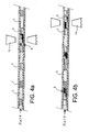
- FIG. 4a A first application is shown in Figure 4a.
- a single ferrofluid train (3) is used with several plugs (7) of mineral oil.
- an alternation of fluid of interest (L) and oil plugs (7) precedes a ferrofluid train (3).
- FIG. 4b A second application is shown in Figure 4b.
- several ferrofluids train (3) are used alternately with several fluid plugs (L) of interest.
- a pressure ⁇ p causes the flow of fluid plugs L in the capillary.
- the magnetic system (11) allows as in Example 1 to block or unblock this flow.
- This example shows that additional plugs of oil without a ferrofluid plug make it possible, for example, to isolate biological reagents from one plug to the other.
- Example 2 the same ferrofluid train used in Example 1 is used in an application shown diagrammatically in FIG. 4c.
- This application differs from that shown in FIG. 4a, in that the magnetic system is mobile according to the arrows indicated in this figure.
- the displacement of the magnetic field serves as motive force for the movement of the ferrofluid train in the capillary, that is to say also of the fluid of interest (L).
- the application of a driving pressure is not necessary here.
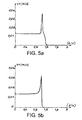
- FIGS. 5a and 5b numerical simulations using the Matlab (registered trademark) software show, for example, the cessation of the flow in a capillary comprising a succession of ferrofluid trains as in FIG. 4b and of water.
- the magnetic field is created either by two permanent magnets (fig.5a) in opposition or by a solenoid (fig.5b). In these two cases, magnets and solenoid, the magnetic field is 350 Gauss on the axis at the center of the capillary.
- the diameter of the solenoid is 1 mm and it has 10 turns and its length is that of a ferrofluid plug: 2 mm. For the 2 permanent magnets facing each other, the dimensions are 3 cm x 1 cm x 1 mm.
- FIGS. 6a and 6b are photographs showing the embodiment of the process of the present invention in a 300 ⁇ m diameter capillary made of teflon (registered trademark) and using mineral oil plugs (reference Sigma-Aldrich M3516), colorless, of on both sides of an ion ferrofluid plug such as that described in Example 1, to avoid contamination with the aqueous phase plugs (fluid of interest) stained with methylene blue.
Landscapes
- Chemical & Material Sciences (AREA)
- Dispersion Chemistry (AREA)
- Health & Medical Sciences (AREA)
- Analytical Chemistry (AREA)
- General Health & Medical Sciences (AREA)
- Hematology (AREA)
- Clinical Laboratory Science (AREA)
- Chemical Kinetics & Catalysis (AREA)
- Physical Or Chemical Processes And Apparatus (AREA)
- Automatic Analysis And Handling Materials Therefor (AREA)
- Manufacturing Of Micro-Capsules (AREA)
- Feeding, Discharge, Calcimining, Fusing, And Gas-Generation Devices (AREA)
Claims (16)
- Verfahren zur Förderung bzw. Verschiebung einer interessierenden Flüssigkeit in einer Kapillare, die folgenden Schritte umfassend:- man bildet in der genannten Kapillare einen Ferrofluid-Zug, wobei der Ferrofluid-Zug einen Ferrofluid-Pfropfen und an wenigstens einem der beiden Enden des Ferrofluid-Pfropfens und mit diesem vereinigt einen Pfropfen aus einer mit dem Ferrofluid und dem interessierenden Fluid nicht mischbaren Flüssigkeit umfasst,- man sieht in der Kapillare das genannte interessierende Fluid in unmittelbarer Nähe des Pfropfens aus der mit dem Ferrofluid und dem interessierenden Fluid nicht mischbaren Flüssigkeit vor,- man steuert die Verschiebung der interessierenden Flüssigkeit in der genannten Kapillare durch die Wirkung eines Magnetfelds auf den Ferrofluid-Pfropfen, das erzeugt wird durch ein außerhalb der Kapillare angeordnetes magnetisches System.
- Verfahren nach Anspruch 1 bei dem das Ferrofluid ein ionisches Ferrofluid ist.
- Verfahren nach Anspruch 1 oder 2, bei dem die Kapillare eine Kapillare ist, deren Innenwand hydrophob ist.
- Verfahren nach Anspruch 1, bei dem die Kapillare einen Durchmesser unter 1 mm hat.
- Verfahren nach Anspruch 1, das außerdem einen Schritt zur Vorausbenetzung der Innenwand der Kapillare mit Öl umfasst, ehe der genannte Ferrofluid-Zug in der Kapillare gebildet wird.
- Verfahren nach Anspruch 1, bei dem ein Pfropfen aus einer mit dem Ferrofluid und dem interessierenden Fluid nicht mischbaren Flüssigkeit an jedem der beiden Enden des Ferrofluidpfropfens vorgesehen ist.
- Verfahren nach Anspruch 1, bei dem in der Kapillare eine Vielzahl von Ferrofluid-Zügen gebildet wird.
- Verfahren nach Anspruch 1, bei dem zwischen zwei Pfropfen aus dem interessierenden Fluid wenigstens ein Pfropfen aus einer mit dem Ferrofluid und dem interessierenden Fluid nicht mischbaren Flüssigkeit vorgesehen ist.
- Fluidische Mikrosysteme zur Verschiebung eines interessierenden Fluids, einerseits eine Kapillare (1), in der wenigstens ein Ferrofluid-Zug (3) vorgesehen ist, und andererseits, außerhalb der genannten Kapillare, ein magnetisches System (11) umfassend, das ermöglicht, ein Magnetfeld zu erzeugen, um die Verschiebung des Ferrofluid-Zugs in der Kapillare zu steuern, wobei der genannte Ferrofluid-Zug (3) einen Ferrofluid-Pfropfen (5) und einen Pfropfen (7) aus einer nicht mit dem Ferrofluid und dem interessierenden Fluid mischbaren Flüssigkeit umfasst, der sich an wenigstens einem der beiden Enden des Ferrofluid-Pfropfens befindet und mit diesem vereinigt ist.
- Fluidisches Mikrosystem nach Anspruch 9, bei dem das Ferrofluid ein ionisches Ferrofluid ist.
- Fluldisches Mikrosystem nach Anspruch 9 oder 10, bei dem die Kapillare eine Kapillare ist, deren Innenwand hydrophob ist.
- Fluidisches Mikrosystem nach Anspruch 9, bei dem die Kapillare einen Durchmesser unter 1 mm hat.
- Fluidisches Mikrosystem nach Anspruch 9, bei dem ein Pfropfen aus einer mit dem Ferrofluid und dem interessierenden Fluid nicht mischbaren Flüssigkeit an jedem der beiden Enden des Ferrofluidpfropfens vorgesehen ist.
- Fluidisches Mikrosystem nach Anspruch 9, das eine Vielzahl Ferrofluid-Züge umfasst.
- Fluidisches Mikrosystem nach Anspruch 9, bei dem in der Kapillare wenigstens ein Pfropfen aus einer mit dem Ferrofluid und dem interessierenden Fluid nicht mischbaren Flüssigkeit zwischen zwei Pfropfen aus dem interessierenden Fluid vorgesehen ist.
- Verwendung eines fluidischen Mikrosystems nach Anspruch 9 in einem automatisierten In-Vitro-Diagnosesystem oder einem System zur Detektion biologischer Kontaminationsstoffe.
Applications Claiming Priority (3)
| Application Number | Priority Date | Filing Date | Title |
|---|---|---|---|
| FR0112192 | 2001-09-21 | ||
| FR0112192A FR2829948B1 (fr) | 2001-09-21 | 2001-09-21 | Procede de deplacement d'un fluide d'interet dans un capillaire et microsysteme fluidique |
| PCT/FR2002/003207 WO2003026798A1 (fr) | 2001-09-21 | 2002-09-19 | Procede de deplacement d'un fluide d'interet dans un capillaire et microsysteme fluidique |
Publications (2)
| Publication Number | Publication Date |
|---|---|
| EP1444042A1 EP1444042A1 (de) | 2004-08-11 |
| EP1444042B1 true EP1444042B1 (de) | 2006-07-12 |
Family
ID=8867494
Family Applications (1)
| Application Number | Title | Priority Date | Filing Date |
|---|---|---|---|
| EP02799424A Expired - Lifetime EP1444042B1 (de) | 2001-09-21 | 2002-09-19 | Verfahren zur förderung einer flüssigkeit in einer kapillare und fluidisches mikrosystem |
Country Status (7)
| Country | Link |
|---|---|
| US (1) | US20040241693A1 (de) |
| EP (1) | EP1444042B1 (de) |
| JP (1) | JP4106328B2 (de) |
| AT (1) | ATE332748T1 (de) |
| DE (1) | DE60213120T2 (de) |
| FR (1) | FR2829948B1 (de) |
| WO (1) | WO2003026798A1 (de) |
Families Citing this family (47)
| Publication number | Priority date | Publication date | Assignee | Title |
|---|---|---|---|---|
| JP3711988B2 (ja) * | 2003-05-12 | 2005-11-02 | 株式会社日立製作所 | 微粒子アレー分析システム、微粒子アレーキットおよび化学分析方法 |
| US7247487B2 (en) * | 2003-06-18 | 2007-07-24 | Ortho-Clinical Diagnostics | Reducing working fluid dilution in liquid systems |
| FR2863626B1 (fr) * | 2003-12-15 | 2006-08-04 | Commissariat Energie Atomique | Procede et dispositif de division d'un echantillon biologique par effet magnetique |
| US20080226500A1 (en) * | 2004-01-15 | 2008-09-18 | Mitsuhiro Shikida | Chemical Analytic Apparatus and Chemical Analytic Method |
| JP2005349254A (ja) * | 2004-06-08 | 2005-12-22 | National Univ Corp Shizuoka Univ | 微小物質の再配置方法 |
| EP1802395B1 (de) * | 2004-09-09 | 2020-01-22 | Institut Curie | Ein kollineares elektrisches feld verwendende mikrofluidvorrichtung |
| US7968287B2 (en) | 2004-10-08 | 2011-06-28 | Medical Research Council Harvard University | In vitro evolution in microfluidic systems |
| WO2007024798A2 (en) * | 2005-08-22 | 2007-03-01 | Applera Corporation | Apparatus, system, and method using immiscible-fluid-discrete-volumes |
| GB2433259A (en) * | 2005-11-30 | 2007-06-20 | Deltadot Ltd | Nucleic acid amplification method and microfluidic apparatus therefore |
| WO2007081385A2 (en) | 2006-01-11 | 2007-07-19 | Raindance Technologies, Inc. | Microfluidic devices and methods of use in the formation and control of nanoreactors |
| US9562837B2 (en) | 2006-05-11 | 2017-02-07 | Raindance Technologies, Inc. | Systems for handling microfludic droplets |
| EP2530167A1 (de) | 2006-05-11 | 2012-12-05 | Raindance Technologies, Inc. | Mikrofluidische Vorrichtungen |
| US7794665B2 (en) | 2006-07-17 | 2010-09-14 | Industrial Technology Research Institute | Fluidic device |
| US7959876B2 (en) | 2006-07-17 | 2011-06-14 | Industrial Technology Research Institute | Fluidic device |
| WO2008097559A2 (en) | 2007-02-06 | 2008-08-14 | Brandeis University | Manipulation of fluids and reactions in microfluidic systems |
| US8592221B2 (en) | 2007-04-19 | 2013-11-26 | Brandeis University | Manipulation of fluids, fluid components and reactions in microfluidic systems |
| US8222049B2 (en) * | 2008-04-25 | 2012-07-17 | Opko Diagnostics, Llc | Flow control in microfluidic systems |
| DE102008031798A1 (de) * | 2008-07-04 | 2010-01-07 | Bürkert Werke GmbH & Co. KG | Verfahren zur Übermittlung von Informationen |
| FR2933315B1 (fr) * | 2008-07-07 | 2012-02-10 | Commissariat Energie Atomique | Dispositif microfluidique de deplacement de liquide |
| EP4047367A1 (de) | 2008-07-18 | 2022-08-24 | Bio-Rad Laboratories, Inc. | Verfahren zum nachweis von zielanalyten unter verwendung von tropfenbibliotheken |
| US12038438B2 (en) | 2008-07-18 | 2024-07-16 | Bio-Rad Laboratories, Inc. | Enzyme quantification |
| FR2934361B1 (fr) * | 2008-07-22 | 2012-12-28 | Commissariat Energie Atomique | Dispositif de variation de pression d'un fluide pneumatique par deplacement de gouttes de liquide et pompe a chaleur utilisant un tel dispositif |
| US9180453B2 (en) * | 2008-08-15 | 2015-11-10 | University Of Washington | Method and apparatus for the discretization and manipulation of sample volumes |
| WO2010111231A1 (en) | 2009-03-23 | 2010-09-30 | Raindance Technologies, Inc. | Manipulation of microfluidic droplets |
| EP4484577A3 (de) | 2010-02-12 | 2025-03-26 | Bio-Rad Laboratories, Inc. | Digitale analytanalyse |
| US9366632B2 (en) | 2010-02-12 | 2016-06-14 | Raindance Technologies, Inc. | Digital analyte analysis |
| US10351905B2 (en) | 2010-02-12 | 2019-07-16 | Bio-Rad Laboratories, Inc. | Digital analyte analysis |
| US9399797B2 (en) | 2010-02-12 | 2016-07-26 | Raindance Technologies, Inc. | Digital analyte analysis |
| JP2012042443A (ja) * | 2010-07-22 | 2012-03-01 | Tokyo Electron Ltd | 液滴移動装置、液滴移動方法及び血漿分離装置並びに血漿分離方法 |
| US9562897B2 (en) | 2010-09-30 | 2017-02-07 | Raindance Technologies, Inc. | Sandwich assays in droplets |
| JP5218525B2 (ja) * | 2010-11-09 | 2013-06-26 | 株式会社デンソー | 熱輸送流体が流通する装置 |
| EP3412778A1 (de) | 2011-02-11 | 2018-12-12 | Raindance Technologies, Inc. | Verfahren zur bildung gemischter tröpfchen |
| WO2012112804A1 (en) | 2011-02-18 | 2012-08-23 | Raindance Technoligies, Inc. | Compositions and methods for molecular labeling |
| EP3216872B1 (de) | 2011-06-02 | 2020-04-01 | Bio-Rad Laboratories, Inc. | Enzymquantifizierung |
| US8658430B2 (en) | 2011-07-20 | 2014-02-25 | Raindance Technologies, Inc. | Manipulating droplet size |
| US9347056B2 (en) | 2012-10-26 | 2016-05-24 | Seiko Epson Corporation | Nucleic acid extraction device, and nucleic acid extraction method, nucleic acid extraction kit, and nucleic acid extraction apparatus, each using the same |
| JP2014176304A (ja) * | 2013-03-13 | 2014-09-25 | Seiko Epson Corp | 核酸増幅反応用カートリッジ |
| JP2014176305A (ja) * | 2013-03-13 | 2014-09-25 | Seiko Epson Corp | 核酸増幅反応用カートリッジ |
| JP2014176306A (ja) * | 2013-03-13 | 2014-09-25 | Seiko Epson Corp | 核酸増幅反応用カートリッジ |
| JP6506747B2 (ja) | 2013-06-25 | 2019-04-24 | ユニバーシティ オブ ワシントン スルー イッツ センター フォー コマーシャリゼーション | サンプル体積の自己デジタル処理 |
| US11901041B2 (en) | 2013-10-04 | 2024-02-13 | Bio-Rad Laboratories, Inc. | Digital analysis of nucleic acid modification |
| US9944977B2 (en) | 2013-12-12 | 2018-04-17 | Raindance Technologies, Inc. | Distinguishing rare variations in a nucleic acid sequence from a sample |
| US9583257B2 (en) * | 2014-07-18 | 2017-02-28 | Nokia Technologies Oy | Microfluidics controlled tunable coil |
| JP6868289B2 (ja) | 2015-07-07 | 2021-05-12 | ユニバーシティ オブ ワシントンUniversity of Washington | サンプルの自己デジタル化のためのシステム、方法、およびデバイス |
| US10647981B1 (en) | 2015-09-08 | 2020-05-12 | Bio-Rad Laboratories, Inc. | Nucleic acid library generation methods and compositions |
| CN106540757B (zh) * | 2015-09-21 | 2018-10-26 | 中国科学院大连化学物理研究所 | 一种磁力驱动液体定量操控装置 |
| EP3649348A4 (de) * | 2017-07-07 | 2021-03-24 | Tikomat Oy | Mikrofluidische vorrichtung |
Family Cites Families (9)
| Publication number | Priority date | Publication date | Assignee | Title |
|---|---|---|---|---|
| US5192504A (en) * | 1985-04-11 | 1993-03-09 | Technicon Instruments Corporation | Flushable low carryover container |
| US5005639A (en) * | 1988-03-24 | 1991-04-09 | The United States Of America As Represented By The Secretary Of The Air Force | Ferrofluid piston pump for use with heat pipes or the like |
| US5856174A (en) * | 1995-06-29 | 1999-01-05 | Affymetrix, Inc. | Integrated nucleic acid diagnostic device |
| US6130098A (en) * | 1995-09-15 | 2000-10-10 | The Regents Of The University Of Michigan | Moving microdroplets |
| US5962215A (en) * | 1996-04-05 | 1999-10-05 | Mercury Diagnostics, Inc. | Methods for testing the concentration of an analyte in a body fluid |
| CN1329729C (zh) * | 1996-06-28 | 2007-08-01 | 卡钳生命科学股份有限公司 | 微流体系统 |
| US6524456B1 (en) * | 1999-08-12 | 2003-02-25 | Ut-Battelle, Llc | Microfluidic devices for the controlled manipulation of small volumes |
| WO2001026813A2 (en) * | 1999-10-08 | 2001-04-19 | Micronics, Inc. | Microfluidics without electrically of mechanically operated pumps |
| US6408884B1 (en) * | 1999-12-15 | 2002-06-25 | University Of Washington | Magnetically actuated fluid handling devices for microfluidic applications |
-
2001
- 2001-09-21 FR FR0112192A patent/FR2829948B1/fr not_active Expired - Fee Related
-
2002
- 2002-09-19 JP JP2003530425A patent/JP4106328B2/ja not_active Expired - Fee Related
- 2002-09-19 DE DE60213120T patent/DE60213120T2/de not_active Expired - Lifetime
- 2002-09-19 AT AT02799424T patent/ATE332748T1/de not_active IP Right Cessation
- 2002-09-19 US US10/488,435 patent/US20040241693A1/en not_active Abandoned
- 2002-09-19 WO PCT/FR2002/003207 patent/WO2003026798A1/fr not_active Ceased
- 2002-09-19 EP EP02799424A patent/EP1444042B1/de not_active Expired - Lifetime
Also Published As
| Publication number | Publication date |
|---|---|
| ATE332748T1 (de) | 2006-08-15 |
| JP4106328B2 (ja) | 2008-06-25 |
| EP1444042A1 (de) | 2004-08-11 |
| FR2829948B1 (fr) | 2004-07-09 |
| DE60213120D1 (de) | 2006-08-24 |
| JP2005503572A (ja) | 2005-02-03 |
| WO2003026798A1 (fr) | 2003-04-03 |
| DE60213120T2 (de) | 2007-01-11 |
| FR2829948A1 (fr) | 2003-03-28 |
| US20040241693A1 (en) | 2004-12-02 |
Similar Documents
| Publication | Publication Date | Title |
|---|---|---|
| EP1444042B1 (de) | Verfahren zur förderung einer flüssigkeit in einer kapillare und fluidisches mikrosystem | |
| Polson et al. | Electroosmotic flow control of fluids on a capillary electrophoresis microdevice using an applied external voltage | |
| Edgar et al. | Capillary electrophoresis separation in the presence of an immiscible boundary for droplet analysis | |
| US7252928B1 (en) | Methods for prevention of surface adsorption of biological materials to capillary walls in microchannels | |
| Stein et al. | Electrokinetic concentration of DNA polymers in nanofluidic channels | |
| Culbertson et al. | Electroosmotically induced hydraulic pumping on microchips: differential ion transport | |
| US6408884B1 (en) | Magnetically actuated fluid handling devices for microfluidic applications | |
| Tas et al. | Nanofluidic bubble pump using surface tension directed gas injection | |
| US10690290B2 (en) | Particle focusing systems and methods | |
| Cong et al. | Electrokinetic sample preconcentration and hydrodynamic sample injection for microchip electrophoresis using a pneumatic microvalve | |
| Brouzes | Droplet microfluidics for single-cell analysis | |
| Draper et al. | Compartmentalization of electrophoretically separated analytes in a multiphase microfluidic platform | |
| Kokkinis et al. | On-chip microfluidic biosensor using superparamagnetic microparticles | |
| Arango et al. | Electrogates for stop-and-go control of liquid flow in microfluidics | |
| Afshar et al. | Three-dimensional magnetic focusing of superparamagnetic beads for on-chip agglutination assays | |
| CN110914544B (zh) | 用于使液体循环的装置和方法 | |
| US7473361B2 (en) | Diffusion-based molecular separation in structured microfluidic devices | |
| Lane et al. | Perpetual sedimentation for the continuous delivery of particulate suspensions | |
| EP2877272A1 (de) | Ölentfernung aus einem strom von aus öl abgeschiedenen probentröpfchen | |
| CN107614421A (zh) | 微流体传输 | |
| Lee et al. | Elastocapillarity-assisted spontaneous particle clustering system: Parallel observation of enhanced interparticle reaction utilizing evaporative preconcentration | |
| Ahn et al. | A novel type of a microfluidic system using ferrofluids for an application of μ-TAS | |
| Zhu et al. | Cell loss in integrated microfluidic device | |
| Xu et al. | Three-dimensional (3D) hydrodynamic focusing for continuous sampling and analysis of adherent cells | |
| EP3141298A1 (de) | Durch plasma-mikrotexturierung hergestellte, polymere mikrofluidische vorrichtung zur nukleinsäurereinigung |
Legal Events
| Date | Code | Title | Description |
|---|---|---|---|
| PUAI | Public reference made under article 153(3) epc to a published international application that has entered the european phase |
Free format text: ORIGINAL CODE: 0009012 |
|
| 17P | Request for examination filed |
Effective date: 20040217 |
|
| AK | Designated contracting states |
Kind code of ref document: A1 Designated state(s): AT BE BG CH CY CZ DE DK EE ES FI FR GB GR IE IT LI LU MC NL PT SE SK TR |
|
| GRAP | Despatch of communication of intention to grant a patent |
Free format text: ORIGINAL CODE: EPIDOSNIGR1 |
|
| GRAS | Grant fee paid |
Free format text: ORIGINAL CODE: EPIDOSNIGR3 |
|
| GRAA | (expected) grant |
Free format text: ORIGINAL CODE: 0009210 |
|
| AK | Designated contracting states |
Kind code of ref document: B1 Designated state(s): AT BE BG CH CY CZ DE DK EE ES FI FR GB GR IE IT LI LU MC NL PT SE SK TR |
|
| PG25 | Lapsed in a contracting state [announced via postgrant information from national office to epo] |
Ref country code: NL Free format text: LAPSE BECAUSE OF FAILURE TO SUBMIT A TRANSLATION OF THE DESCRIPTION OR TO PAY THE FEE WITHIN THE PRESCRIBED TIME-LIMIT Effective date: 20060712 Ref country code: IE Free format text: LAPSE BECAUSE OF FAILURE TO SUBMIT A TRANSLATION OF THE DESCRIPTION OR TO PAY THE FEE WITHIN THE PRESCRIBED TIME-LIMIT Effective date: 20060712 Ref country code: AT Free format text: LAPSE BECAUSE OF FAILURE TO SUBMIT A TRANSLATION OF THE DESCRIPTION OR TO PAY THE FEE WITHIN THE PRESCRIBED TIME-LIMIT Effective date: 20060712 Ref country code: CZ Free format text: LAPSE BECAUSE OF FAILURE TO SUBMIT A TRANSLATION OF THE DESCRIPTION OR TO PAY THE FEE WITHIN THE PRESCRIBED TIME-LIMIT Effective date: 20060712 Ref country code: SK Free format text: LAPSE BECAUSE OF FAILURE TO SUBMIT A TRANSLATION OF THE DESCRIPTION OR TO PAY THE FEE WITHIN THE PRESCRIBED TIME-LIMIT Effective date: 20060712 Ref country code: FI Free format text: LAPSE BECAUSE OF FAILURE TO SUBMIT A TRANSLATION OF THE DESCRIPTION OR TO PAY THE FEE WITHIN THE PRESCRIBED TIME-LIMIT Effective date: 20060712 |
|
| REG | Reference to a national code |
Ref country code: GB Ref legal event code: FG4D Free format text: NOT ENGLISH |
|
| REG | Reference to a national code |
Ref country code: CH Ref legal event code: EP |
|
| REG | Reference to a national code |
Ref country code: IE Ref legal event code: FG4D Free format text: LANGUAGE OF EP DOCUMENT: FRENCH |
|
| REF | Corresponds to: |
Ref document number: 60213120 Country of ref document: DE Date of ref document: 20060824 Kind code of ref document: P |
|
| PG25 | Lapsed in a contracting state [announced via postgrant information from national office to epo] |
Ref country code: MC Free format text: LAPSE BECAUSE OF NON-PAYMENT OF DUE FEES Effective date: 20060930 Ref country code: BE Free format text: LAPSE BECAUSE OF NON-PAYMENT OF DUE FEES Effective date: 20060930 |
|
| PG25 | Lapsed in a contracting state [announced via postgrant information from national office to epo] |
Ref country code: DK Free format text: LAPSE BECAUSE OF FAILURE TO SUBMIT A TRANSLATION OF THE DESCRIPTION OR TO PAY THE FEE WITHIN THE PRESCRIBED TIME-LIMIT Effective date: 20061012 Ref country code: SE Free format text: LAPSE BECAUSE OF FAILURE TO SUBMIT A TRANSLATION OF THE DESCRIPTION OR TO PAY THE FEE WITHIN THE PRESCRIBED TIME-LIMIT Effective date: 20061012 Ref country code: BG Free format text: LAPSE BECAUSE OF FAILURE TO SUBMIT A TRANSLATION OF THE DESCRIPTION OR TO PAY THE FEE WITHIN THE PRESCRIBED TIME-LIMIT Effective date: 20061012 |
|
| PG25 | Lapsed in a contracting state [announced via postgrant information from national office to epo] |
Ref country code: ES Free format text: LAPSE BECAUSE OF FAILURE TO SUBMIT A TRANSLATION OF THE DESCRIPTION OR TO PAY THE FEE WITHIN THE PRESCRIBED TIME-LIMIT Effective date: 20061023 |
|
| GBT | Gb: translation of ep patent filed (gb section 77(6)(a)/1977) |
Effective date: 20061024 |
|
| PG25 | Lapsed in a contracting state [announced via postgrant information from national office to epo] |
Ref country code: PT Free format text: LAPSE BECAUSE OF FAILURE TO SUBMIT A TRANSLATION OF THE DESCRIPTION OR TO PAY THE FEE WITHIN THE PRESCRIBED TIME-LIMIT Effective date: 20061212 |
|
| NLV1 | Nl: lapsed or annulled due to failure to fulfill the requirements of art. 29p and 29m of the patents act | ||
| REG | Reference to a national code |
Ref country code: IE Ref legal event code: FD4D |
|
| PLBE | No opposition filed within time limit |
Free format text: ORIGINAL CODE: 0009261 |
|
| STAA | Information on the status of an ep patent application or granted ep patent |
Free format text: STATUS: NO OPPOSITION FILED WITHIN TIME LIMIT |
|
| 26N | No opposition filed |
Effective date: 20070413 |
|
| BERE | Be: lapsed |
Owner name: COMMISSARIAT A L'ENERGIE ATOMIQUE Effective date: 20060930 |
|
| PG25 | Lapsed in a contracting state [announced via postgrant information from national office to epo] |
Ref country code: GR Free format text: LAPSE BECAUSE OF FAILURE TO SUBMIT A TRANSLATION OF THE DESCRIPTION OR TO PAY THE FEE WITHIN THE PRESCRIBED TIME-LIMIT Effective date: 20061013 |
|
| PG25 | Lapsed in a contracting state [announced via postgrant information from national office to epo] |
Ref country code: EE Free format text: LAPSE BECAUSE OF FAILURE TO SUBMIT A TRANSLATION OF THE DESCRIPTION OR TO PAY THE FEE WITHIN THE PRESCRIBED TIME-LIMIT Effective date: 20060712 |
|
| PG25 | Lapsed in a contracting state [announced via postgrant information from national office to epo] |
Ref country code: LU Free format text: LAPSE BECAUSE OF NON-PAYMENT OF DUE FEES Effective date: 20060919 Ref country code: TR Free format text: LAPSE BECAUSE OF FAILURE TO SUBMIT A TRANSLATION OF THE DESCRIPTION OR TO PAY THE FEE WITHIN THE PRESCRIBED TIME-LIMIT Effective date: 20060712 |
|
| PG25 | Lapsed in a contracting state [announced via postgrant information from national office to epo] |
Ref country code: CY Free format text: LAPSE BECAUSE OF FAILURE TO SUBMIT A TRANSLATION OF THE DESCRIPTION OR TO PAY THE FEE WITHIN THE PRESCRIBED TIME-LIMIT Effective date: 20060712 |
|
| PGFP | Annual fee paid to national office [announced via postgrant information from national office to epo] |
Ref country code: DE Payment date: 20130910 Year of fee payment: 12 Ref country code: CH Payment date: 20130911 Year of fee payment: 12 |
|
| PGFP | Annual fee paid to national office [announced via postgrant information from national office to epo] |
Ref country code: GB Payment date: 20130920 Year of fee payment: 12 |
|
| PGFP | Annual fee paid to national office [announced via postgrant information from national office to epo] |
Ref country code: IT Payment date: 20130920 Year of fee payment: 12 |
|
| PGFP | Annual fee paid to national office [announced via postgrant information from national office to epo] |
Ref country code: FR Payment date: 20130930 Year of fee payment: 12 |
|
| REG | Reference to a national code |
Ref country code: DE Ref legal event code: R119 Ref document number: 60213120 Country of ref document: DE |
|
| REG | Reference to a national code |
Ref country code: CH Ref legal event code: PL |
|
| GBPC | Gb: european patent ceased through non-payment of renewal fee |
Effective date: 20140919 |
|
| REG | Reference to a national code |
Ref country code: FR Ref legal event code: ST Effective date: 20150529 |
|
| PG25 | Lapsed in a contracting state [announced via postgrant information from national office to epo] |
Ref country code: CH Free format text: LAPSE BECAUSE OF NON-PAYMENT OF DUE FEES Effective date: 20140930 Ref country code: GB Free format text: LAPSE BECAUSE OF NON-PAYMENT OF DUE FEES Effective date: 20140919 Ref country code: DE Free format text: LAPSE BECAUSE OF NON-PAYMENT OF DUE FEES Effective date: 20150401 Ref country code: LI Free format text: LAPSE BECAUSE OF NON-PAYMENT OF DUE FEES Effective date: 20140930 |
|
| PG25 | Lapsed in a contracting state [announced via postgrant information from national office to epo] |
Ref country code: IT Free format text: LAPSE BECAUSE OF NON-PAYMENT OF DUE FEES Effective date: 20140919 Ref country code: FR Free format text: LAPSE BECAUSE OF NON-PAYMENT OF DUE FEES Effective date: 20140930 |