EP1444162B1 - Grue automotrice munie d'un dispositif d'augmentation de levage - Google Patents
Grue automotrice munie d'un dispositif d'augmentation de levage Download PDFInfo
- Publication number
- EP1444162B1 EP1444162B1 EP02774419A EP02774419A EP1444162B1 EP 1444162 B1 EP1444162 B1 EP 1444162B1 EP 02774419 A EP02774419 A EP 02774419A EP 02774419 A EP02774419 A EP 02774419A EP 1444162 B1 EP1444162 B1 EP 1444162B1
- Authority
- EP
- European Patent Office
- Prior art keywords
- counterweight
- load
- radius
- truck crane
- parameters
- Prior art date
- Legal status (The legal status is an assumption and is not a legal conclusion. Google has not performed a legal analysis and makes no representation as to the accuracy of the status listed.)
- Expired - Lifetime
Links
- 230000008859 change Effects 0.000 claims description 6
- 230000011664 signaling Effects 0.000 claims description 5
- 230000009471 action Effects 0.000 claims description 3
- 238000010586 diagram Methods 0.000 claims description 2
- 238000002360 preparation method Methods 0.000 claims description 2
- 210000004209 hair Anatomy 0.000 claims 1
- 238000006243 chemical reaction Methods 0.000 abstract description 3
- 238000010276 construction Methods 0.000 description 4
- 230000008901 benefit Effects 0.000 description 3
- 238000011161 development Methods 0.000 description 3
- 230000018109 developmental process Effects 0.000 description 3
- 238000013459 approach Methods 0.000 description 2
- 238000000151 deposition Methods 0.000 description 2
- 230000009467 reduction Effects 0.000 description 2
- 239000007787 solid Substances 0.000 description 2
- 230000003247 decreasing effect Effects 0.000 description 1
- 230000008021 deposition Effects 0.000 description 1
- 238000005516 engineering process Methods 0.000 description 1
- 230000002349 favourable effect Effects 0.000 description 1
- 230000005484 gravity Effects 0.000 description 1
- 238000004519 manufacturing process Methods 0.000 description 1
- 230000007246 mechanism Effects 0.000 description 1
- 238000000034 method Methods 0.000 description 1
- 230000008569 process Effects 0.000 description 1
- 238000004088 simulation Methods 0.000 description 1
- 239000000725 suspension Substances 0.000 description 1
Images
Classifications
-
- B—PERFORMING OPERATIONS; TRANSPORTING
- B66—HOISTING; LIFTING; HAULING
- B66C—CRANES; LOAD-ENGAGING ELEMENTS OR DEVICES FOR CRANES, CAPSTANS, WINCHES, OR TACKLES
- B66C23/00—Cranes comprising essentially a beam, boom, or triangular structure acting as a cantilever and mounted for translatory of swinging movements in vertical or horizontal planes or a combination of such movements, e.g. jib-cranes, derricks, tower cranes
- B66C23/88—Safety gear
- B66C23/90—Devices for indicating or limiting lifting moment
- B66C23/905—Devices for indicating or limiting lifting moment electrical
-
- B—PERFORMING OPERATIONS; TRANSPORTING
- B66—HOISTING; LIFTING; HAULING
- B66C—CRANES; LOAD-ENGAGING ELEMENTS OR DEVICES FOR CRANES, CAPSTANS, WINCHES, OR TACKLES
- B66C23/00—Cranes comprising essentially a beam, boom, or triangular structure acting as a cantilever and mounted for translatory of swinging movements in vertical or horizontal planes or a combination of such movements, e.g. jib-cranes, derricks, tower cranes
- B66C23/62—Constructional features or details
- B66C23/72—Counterweights or supports for balancing lifting couples
- B66C23/74—Counterweights or supports for balancing lifting couples separate from jib
Definitions
- the invention relates to a vehicle crane with an undercarriage and a to a vertical axle pivotally mounted on superstructure, with one on the superstructure hinged, about a horizontal axis pivotable boom device for lifting a load and designed as a superlift load-increasing Counterweight device which is connected to the superstructure in such a way that the Counterweight of the superlift device (SL counterweight) for the execution of Swinging movements of the superstructure can be lifted off the ground and the turning radius of the SL counterweight is variable, and with an electronic control device for Actuation of drive units of the vehicle crane, the at least one Computing device and for the operator of the vehicle crane with a display and an input device is provided for data input, wherein in the electronic Control device is a program stored, which from the parameters Load size and load radius as well as size of SL counterweight and SL counterweight radius taking into account the stability and capacity criteria of the Vehicle crane determines a working field and displays on the display graphically.
- Such a vehicle crane is known from DE-A-199 31 302, which corresponds to the preamble of independent claim 1.
- These mobile cranes are equipped with a crawler track and have a boom via a luffing lattice boom.
- the latter can have one with an am Superstructure mounted and lying in the rocker plane obliquely inclined backwards Mast and an attached Seilabposition in its inclination continuously changed become.
- the superstructure is equipped with a counterweight.
- the SL counterweight can, for example, on a traverse or be arranged on a so-called counterweight car, the or over each a corresponding side suspension is attached to the mast.
- the horizontal distance between the axis of rotation of the upper carriage and the center of gravity of the SL counterweight is called the SL counterweight radius.
- Load radius in relation to the load attached to the crane.
- this is the SL counterweight over a substantially horizontal or at least flat Telescopic rod, for example, by a hydraulic cylinder in its length is changeable, connected to the superstructure.
- a hydraulic cylinder in its length is changeable, connected to the superstructure.
- By retracting or extending the Telescopic pole allows the SL counterweight to a smaller or larger Adjust the radius so that a counterweight torque is adjustable, below which current load torque a problem lifting the SL counterweight, the Usually is on the order of about 30 cm from the ground, is possible.
- Object of the present invention is a generic vehicle crane to improve that lifting tasks for the crane while minimizing the Umrüstaufwands with smallest possible to be carried counterweight with large Safety for the crane operator are feasible.
- the invention provides that in the electronic control device a program is stored, which consists of the parameters load size and load radius and size of SL counterweight and the SL counterweight radius taking into account the Stability and capacity criteria of the vehicle crane a working field for crane parameters determined and graphically displayed on the display for the crane operator, which for the Implementation of the upcoming lifting task can be used.
- the working field points an upper boundary and a lower boundary, within which each in the graph shown in the picture with constant constancy of the remaining parameters are changeable. It is a lifting of the SL counterweight from the ground at any time gerosrleistbar.
- the current size of the graphics parameters is in progress Crane operation can be displayed within the working area. This can basically be realized for example by numbers.
- the display of the current parameter values by a graphical display.
- the current size of the parameters from the current Crane operation is represented by a crosshair.
- a crosshair This is especially recommended if, in advantageous development of the invention, the limitations of the working field by lines, in particular differently structured and / or different colored lines are shown on the display.
- a work field could also be reproduced for example by bar graphs.
- a graphic Representation has the great advantage over the representation of pure numerical values that it is intuitively and therefore quickly and reliably detectable by the crane operator.
- the invention provides preferred development that the electronic control device of the Vehicle crane signaling technology with a sensor for current determination of the set load radius and the set SL counterweight radius is connected.
- the vehicle crane over a mechanical adjustment device for the SL counterweight radius available from the Crane operator can be operated.
- a measuring device for determining the current size to provide the attached to the vehicle crane load and these signaling with to connect the electronic control device.
- a measuring device for determining the current size to provide the attached to the vehicle crane load and these signaling with to connect the electronic control device.
- the electronic control device is in its mode to a Switching mode in which the different load conditions of the Cranes for preparing the workflow of a specific lifting task are simulated.
- the crane operator can already advance under varied parameter settings investigate which concrete attitudes to minimize the total effort are particularly favorable. It is of great advantage if not in the planning mode only the previously mentioned working field for the parameters load radius and SL counterweight radius, but in addition also a diagram of the permissible upper and Lower limit of the permissible load size for a given load radius and given Size of SL counterweight depending on SL counterweight radius is.
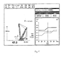
- the display of the control device of a vehicle crane according to the invention shown in Fig. 1 is divided into several areas. It has a narrow upper parameter bar, which shows the settings made for essential parameters of the vehicle crane. These parameters, which are represented as numbers, are explained in their meaning by symbols and thus easily detectable. For example, in the present case it is stated that it is a superlift crane type, that the boom length is 78m and the maximum SL counterweight radius is 25m. The swivel range of the crane is specified as 360 °. As a central ballast 100t are used as a counterweight of the superstructure 280t and as attached SL counterweight a total of 500t. The hook block of the crane has a Seileinscherung of 2 times 22.
- the left part of the screen symbolically shows a vehicle crane with attached SL counterweight lifting off the ground. Since the vehicle crane has a sensor system for determining the current setting of the Auslegeme Trent, the corresponding rocking angle can be displayed. In the present case it is shown as numerical value at 77.3 °. This inclination has a load radius of 17.0 m, which is given as a particularly large and bold numerical value. The associated possible hook height is 48.8m and is indicated on the left edge. The current SL counterweight radius of 22.0 m is also indicated as a numerical value at the lower edge of the left half of the picture.
- E max is the maximum retraction force for the retracting mechanism to adjust the Auslegeme While 18t, of which currently exactly 11.6 are used taking into account the appended load.
- Above the crane symbol is indicated with a windsock sign the current wind speed with 4.6m / s.
- the actually attached load is specified as 830t, which is one Net load of 819t in the present example.
- the latter numerical value is highlighted in color.
- the size of the maximum allowable attachable load with 890t stated. Above these numerical values is in the form of a bar graph and a Numerical value of 93%, how far the maximum permissible load through the actually attached load of 830t is used.
- the lower part of the right Half of the picture is the field of work according to the invention for the two parameters SL counterweight radius (Abscissa) and load radius (ordinate) shown.
- the two radii are given in meters, whereby the meaning of the axes of the Coordinate system is illustrated by appropriate crane symbols.
- the lower Dashed lines indicate the size of the load radius in dependence from the currently set SL counterweight radius are not undershot allowed when the lifted off the ground condition of the SL counterweight shall be. When falling below this dashed lower limit sets the SL counterweight on the ground, so that then no more pivoting of the upper carriage could be made.
- the solid upper bold line gives the permissible upper limit for the load radius as a function of the SL counterweight radius under the set conditions (SL counterweight of 500t and attached load from 830t). Between the solid and the dashed line is the Working field for the crane under the given parameter settings, in the SL counterweight radius and load radius can be safely varied. The current present setting of these two parameters is by a crosshair with a additional small circle made easily detectable. One recognizes the size of the Counterweight radius of 22m and the load radius of 17m, as in the left part is shown numerically at the bottom
- the crane operator thus intuitively detects that in the present example, while maintaining the Load radius of 17m when performing swivel movements to bypass any obstacles in the swivel range of the SL counterweight of the SL counterweight radius be easily changed in the range of 19m to about 23.5m can.
- the Load radius can be safely changed between 16m and 20m.
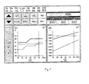
- FIG. 2 shows the screen display in the planning mode.
- the display is designed as a touch screen and thus serves not only as a display unit but also as an input unit for data.
- the respective parameter values can be adjusted by using the appropriate black arrows indicate both left buttons to increase or Decreasing the displayed values.
- the graphic in the lower left part of the Image corresponds to the removable from Figure 1 graphic for the permissible working field.
- a particular advantage of the invention is the fact that the crane operator to each Time can immediately see to what extent he already approaches a critical limit Has. This can happen because unstable states, for example, by under the influence of the wind load the load radius by a pendulum of the load unpredictably changed to an invalid value. It can For example, to a sudden placement of the SL counterweight on the floor come, so that a currently taking place pivoting movement of the upper carriage suddenly would be canceled. This can cause special dangers.
- the inventive design of the control device the crane operator at any time the current position of its operating parameters within the working field easily recognizable, he can make such critical approaches to border areas of avoid it in the first place.
Landscapes
- Engineering & Computer Science (AREA)
- Mechanical Engineering (AREA)
- Jib Cranes (AREA)
Claims (11)
- Grue automotrice comprenant un châssis inférieur et une partie supérieure agencée dessus, pouvant pivoter autour d'un axe vertical, avec un dispositif de flèche, articulé sur la partie supérieure, pouvant pivoter autour d'un axe horizontal et destiné à lever une charge, ainsi qu'un dispositif de contrepoids augmentant la capacité de charge et conçu comme un dispositif Superlift, qui est relié à la partie supérieure de telle manière que le contrepoids du dispositif Superlift (contrepoids SL) puisse être soulevé du sol pour exécuter des mouvements de pivotement de la partie supérieure et que le rayon de pivotement du contrepoids SL puisse être modifié, et avec un dispositif de commande électronique pour actionner des groupes d'entraínement de la grue automotrice, lequel est muni au moins d'un dispositif de traitement des données et, pour l'opérateur de la grue automotrice, d'un écran ainsi que d'un dispositif d'entrée de données, un programme enregistré dans le dispositif de commande électronique déterminant, à partir des paramètres grandeur de charge et rayon de charge, ainsi que grandeur du contrepoids SL et rayon de contrepoids SL, en tenant compte des critères de stabilité et de capacité de la grue automotrice, un champ d'action et le représentant graphiquement sur l'écran,
caractérisée en ce que le champ d'action présente une limite supérieure et une limite inférieure, à l'intérieur desquelles les paramètres représentés sur le graphique peuvent varier sans risque alors que les autres paramètres sont constants, et qu'un soulèvement du contrepoids SL du sol peut alors être garanti et la grandeur réelle des paramètres du graphique pouvant également être indiquée pendant le fonctionnement de la grue à l'intérieur du champ d'action, en particulier de manière graphique. - Grue automotrice selon la revendication 1,
caractérisée en ce que les limites du champ d'action peuvent être représentées par des lignes, en particulier des lignes de structures différentes et/ou de couleurs différentes. - Grue automotrice selon l'une des revendications 1 ou 2,
caractérisée en ce que la grandeur réelle des paramètres représentés peut être indiquée par une croix sur le graphique pendant le fonctionnement de la grue. - Grue automotrice selon l'une des revendications 1 à 3,
caractérisée en ce que la grandeur réelle des paramètres représentés peut être affichée automatiquement en continu pendant le fonctionnement de la grue. - Grue automotrice selon l'une des revendications 1 à 4,
caractérisée en ce que, comme paramètres, le rayon de charge et le rayon de contrepoids SL peuvent être affichés graphiquement. - Grue automotrice selon la revendication 5,
caractérisée en ce que la commande électronique de la grue automotrice est reliée suivant la technique de signalisation à un ensemble de capteurs pour déterminer réellement le rayon de charge réglé et le rayon de contrepoids SL. - Grue automotrice selon l'une des revendications 1 à 6,
caractérisée en ce que le dispositif de commande électronique est relié techniquement par signal à un dispositif de mesure pour déterminer la grandeur de la charge suspendue réellement à la grue automotrice. - Grue automotrice selon l'une des revendications 1 à 7,
caractérisée en ce que le dispositif de commande électronique est relié à un appareil de mesure qui représente une valeur pour la variation de charge provoquée par l'effet du vent ou une telle valeur peut être entrée manuellement dans le dispositif de commande électronique et la modification de la situation de charge causée par la force due au vent peut être prise en compte lors de la détermination du champ d'action. - Grue automotrice selon l'une des revendications 1 à 8,
caractérisée en ce que le dispositif de commande électronique peut être commuté pour passer à un mode d'étude dans lequel les différents états de charge de la grue sont simulés pour préparer le déroulement d'une tâche de levage concrète. - Grue automotrice selon la revendication 9,
caractérisée en ce que, dans le mode d'étude, un diagramme de la limite supérieure et inférieure de la grandeur de charge admissible peut en outre être affiché en fonction du rayon de contrepoids SL pour un rayon de charge donné et une grandeur prédéterminée du contrepoids SL. - Grue automotrice selon l'une des revendications 1 à 10,
caractérisée en ce que le dispositif de traitement des données du dispositif de commande électronique est équipé d'un écran tactile pour l'entrée et la sortie de données.
Applications Claiming Priority (3)
| Application Number | Priority Date | Filing Date | Title |
|---|---|---|---|
| DE10155006 | 2001-11-06 | ||
| DE10155006A DE10155006B4 (de) | 2001-11-06 | 2001-11-06 | Fahrzeugkran mit Superlifteinrichtung |
| PCT/DE2002/003640 WO2003040016A1 (fr) | 2001-11-06 | 2002-09-20 | Grue automotrice munie d'un dispositif d'augmentation de levage |
Publications (2)
| Publication Number | Publication Date |
|---|---|
| EP1444162A1 EP1444162A1 (fr) | 2004-08-11 |
| EP1444162B1 true EP1444162B1 (fr) | 2005-11-16 |
Family
ID=7705139
Family Applications (1)
| Application Number | Title | Priority Date | Filing Date |
|---|---|---|---|
| EP02774419A Expired - Lifetime EP1444162B1 (fr) | 2001-11-06 | 2002-09-20 | Grue automotrice munie d'un dispositif d'augmentation de levage |
Country Status (7)
| Country | Link |
|---|---|
| US (1) | US7252203B2 (fr) |
| EP (1) | EP1444162B1 (fr) |
| JP (1) | JP4199667B2 (fr) |
| CN (1) | CN1331723C (fr) |
| AT (1) | ATE309957T1 (fr) |
| DE (3) | DE10155006B4 (fr) |
| WO (1) | WO2003040016A1 (fr) |
Cited By (3)
| Publication number | Priority date | Publication date | Assignee | Title |
|---|---|---|---|---|
| DE202010014309U1 (de) | 2010-10-14 | 2012-01-18 | Liebherr-Werk Ehingen Gmbh | Kran, insbesondere Raupen- oder Mobilkran |
| DE202010014310U1 (de) | 2010-10-14 | 2012-01-18 | Liebherr-Werk Ehingen Gmbh | Kran, insbesondere Raupen- oder Mobilkran |
| DE102014105618A1 (de) | 2014-04-22 | 2015-10-22 | Terex Cranes Germany Gmbh | Verfahren und Vorrichtung zum Betreiben eines Mobilkrans sowie Mobilkran |
Families Citing this family (43)
| Publication number | Priority date | Publication date | Assignee | Title |
|---|---|---|---|---|
| DE10155006B4 (de) | 2001-11-06 | 2004-12-16 | Terex-Demag Gmbh & Co. Kg | Fahrzeugkran mit Superlifteinrichtung |
| JP5031978B2 (ja) * | 2004-07-05 | 2012-09-26 | 日立建機株式会社 | 建設機械の表示装置 |
| JP4817620B2 (ja) * | 2004-07-05 | 2011-11-16 | 日立建機株式会社 | 建設機械の表示装置 |
| DE102005059768A1 (de) | 2005-07-22 | 2007-01-25 | Liebherr-Werk Ehingen Gmbh | Kran, vorzugsweise Raupen- oder Fahrzeugkran |
| DE102006027202A1 (de) * | 2006-06-12 | 2007-12-13 | Liebherr-Werk Nenzing Gmbh, Nenzing | Kraneinsatzplaner |
| US7967158B2 (en) | 2006-10-27 | 2011-06-28 | Manitowoc Crane Companies, Llc | Mobile lift crane with variable position counterweight |
| US7546928B2 (en) * | 2006-10-27 | 2009-06-16 | Manitowoc Crane Companies, Inc. | Mobile lift crane with variable position counterweight |
| TWI444939B (zh) * | 2008-01-10 | 2014-07-11 | Univ Nat Taiwan | 工程吊車之模擬系統及其方法 |
| US8317453B2 (en) * | 2008-05-15 | 2012-11-27 | Ray Givens | Compound-arm manipulator |
| CN101624165B (zh) * | 2008-07-07 | 2011-06-29 | 徐州重型机械有限公司 | 组合平衡重装置及采用该装置的起重机 |
| US9278834B2 (en) | 2009-08-06 | 2016-03-08 | Manitowoc Crane Group, LLC | Lift crane with moveable counterweight |
| DE202009011577U1 (de) * | 2009-08-26 | 2011-01-05 | Liebherr-Werk Ehingen Gmbh | Kran |
| CN101774514B (zh) * | 2010-01-26 | 2012-02-22 | 昆山三一机械有限公司 | 履带起重机超起配重无级变幅机构及其操作方法 |
| BRPI1001193A2 (pt) * | 2010-02-11 | 2012-07-03 | Vinicius De Carvalho Cal | aperfeiçoamento em grua e processo de controle de contrapeso em uma grua, em tempo real |
| JP5653197B2 (ja) | 2010-12-07 | 2015-01-14 | 株式会社タダノ | クレーン装置 |
| DE102012002040B4 (de) | 2012-02-02 | 2022-07-07 | Liebherr-Werk Ehingen Gmbh | Verfahren zum Betrieb eines Krans und Kran |
| JP5303611B2 (ja) * | 2011-06-29 | 2013-10-02 | アンリツ株式会社 | 移動通信端末試験装置及び移動通信端末試験方法 |
| DE102011108284A1 (de) * | 2011-07-21 | 2013-01-24 | Liebherr-Werk Ehingen Gmbh | Kransteuerung und Kran |
| EP2551233A1 (fr) * | 2011-07-28 | 2013-01-30 | Gamesa Innovation & Technology, S.L. | Grue et système de commande de grue |
| US10162797B1 (en) * | 2012-04-13 | 2018-12-25 | Design Data Corporation | System for determining structural member liftability |
| US10410124B1 (en) | 2013-01-21 | 2019-09-10 | Link-Belt Cranes, L.P., Lllp | Display for displaying lifting capacity of a lifting machine and related methods |
| DE202013003782U1 (de) | 2013-04-22 | 2013-05-07 | Manitowoc Crane Group France Sas | Sensorbasierte Überwachung von Windrichtung und Wärmeeinstrahlung für ein mobiles Arbeitsgerät |
| CN110255402B (zh) | 2014-01-27 | 2022-02-18 | 马尼托瓦克起重机有限责任公司 | 带有改进的可动配重的吊升起重机 |
| US10183848B2 (en) | 2014-01-27 | 2019-01-22 | Manitowoc Crane Companies, Llc | Height adjustment mechanism for an auxiliary member on a crane |
| US9783395B2 (en) * | 2015-03-31 | 2017-10-10 | Manitowoc Crane Companies, Llc | System and method for crane counterweight positioning |
| KR102389591B1 (ko) * | 2015-04-02 | 2022-04-22 | 현대두산인프라코어(주) | 건설기계의 버츄얼 시뮬레이터 |
| JP6412280B2 (ja) * | 2015-06-12 | 2018-10-24 | マニタウォック クレイン カンパニーズ, エルエルシーManitowoc Crane Companies, Llc | 中間カウンターウェイト位置での荷重表の計算のためのシステム及び方法 |
| FR3037681B1 (fr) * | 2015-06-18 | 2017-11-24 | Manitowoc Crane Group France | Procede de definition d’une courbe de charges optimisee pour grue, procede et dispositif de controle pour controler la charge suspendue a une grue a partir de la courbe de charges optimisee |
| CN104986057B (zh) | 2015-07-22 | 2017-06-09 | 北京交通大学 | 轨道交通负电压回流直流供电系统 |
| JP6260591B2 (ja) * | 2015-07-22 | 2018-01-17 | コベルコ建機株式会社 | クレーン、およびクレーンのカウンタウェイトの位置調整方法 |
| JP6520562B2 (ja) * | 2015-08-24 | 2019-05-29 | コベルコ建機株式会社 | 移動式クレーンのウェイト浮き量調整装置及びウェイト浮き量調整方法 |
| CN108290722B (zh) * | 2015-10-16 | 2021-07-09 | 帕尔芬杰尔股份有限公司 | 包括控制装置和移动式控制模块的组件和液压起重设备 |
| US11142442B2 (en) | 2017-02-10 | 2021-10-12 | Arrow Acquisition, Llc | System and method for dynamically controlling the stability of an industrial vehicle |
| US10703612B2 (en) | 2017-11-10 | 2020-07-07 | Manitowoc Crane Companies, Llc | System and method for calculation of capacity charts at a locked counterweight position |
| DE102017131264A1 (de) * | 2017-12-22 | 2019-06-27 | Liebherr-Hydraulikbagger Gmbh | Baumaschine, insbesondere Erdbewegungsmaschine mit einem Bedienpult |
| JP7031315B2 (ja) * | 2018-01-12 | 2022-03-08 | コベルコ建機株式会社 | 高さ調節補助装置、これを備えたクレーン及び高さ調節方法 |
| WO2020256106A1 (fr) * | 2019-06-20 | 2020-12-24 | 株式会社タダノ | Système d'affichage à plage mobile et grue équipée d'un système d'affichage à plage mobile |
| CN110885006B (zh) * | 2019-12-03 | 2020-11-13 | 深知智能科技(金华)有限公司 | 一种起重机工作装置作业姿态自动调整控制方法及系统 |
| JP7840640B2 (ja) | 2020-04-16 | 2026-04-06 | タダノ デマグ ゲーエムベーハー | 車両クレーン及びそのジブへの荷重を低減する方法 |
| CN111348568B (zh) * | 2020-04-22 | 2025-04-04 | 浙江三一装备有限公司 | 一种超起配重的变幅移动方法、变幅移动系统及起重机 |
| DE102021102699A1 (de) | 2021-02-05 | 2022-08-11 | Liebherr-Werk Biberach Gmbh | Kran |
| CN114044452B (zh) * | 2021-10-27 | 2023-06-23 | 浙江三一装备有限公司 | 作业机械作业控制方法、装置及作业机械 |
| US12606424B2 (en) | 2022-01-26 | 2026-04-21 | Electronic Theatre Controls, Inc. | Digital interface for a manual counterweight hoist |
Family Cites Families (15)
| Publication number | Priority date | Publication date | Assignee | Title |
|---|---|---|---|---|
| DE3824732A1 (de) * | 1988-07-21 | 1990-02-15 | Mannesmann Ag | Kran, insbesondere grosskran |
| ATE185772T1 (de) * | 1988-12-27 | 1999-11-15 | Kato Seisakusho Kk | Kransicherheitsvorrichtung |
| US5730305A (en) * | 1988-12-27 | 1998-03-24 | Kato Works Co., Ltd. | Crane safety apparatus |
| DE4030954C2 (de) * | 1990-09-29 | 1994-08-04 | Danfoss As | Verfahren zur Steuerung der Bewegung eines hydraulisch bewegbaren Arbeitsgeräts und Bahnsteuereinrichtung zur Durchführung des Verfahrens |
| JPH0781887A (ja) * | 1993-09-10 | 1995-03-28 | Komatsu Mec Corp | クレーンの安全表示装置 |
| WO1996027548A1 (fr) * | 1995-03-03 | 1996-09-12 | Komatsu Ltd. | Dispositif destine a indiquer la plage de mobilite d'un vehicule a grue mobile |
| DE19538264C2 (de) * | 1995-10-13 | 1999-02-18 | Pietzsch Automatisierungstech | Verfahren und interaktive Bedienkonsole zur Vorbereitung und Einrichtung eines mobilen Arbeitsgerätes |
| JP3136110B2 (ja) | 1996-04-09 | 2001-02-19 | 日立建機株式会社 | クレーンの仕様表示装置 |
| US6744372B1 (en) * | 1997-02-27 | 2004-06-01 | Jack B. Shaw | Crane safety devices and methods |
| JP2000044177A (ja) | 1998-07-29 | 2000-02-15 | Komatsu Ltd | クレーンの作業制限領域表示装置及びその表示方法 |
| DE19857779A1 (de) * | 1998-12-04 | 2000-06-15 | Mannesmann Ag | Kran, insbesondere Fahrzeugkran |
| JP2000344470A (ja) * | 1999-03-31 | 2000-12-12 | Kobelco Contstruction Machinery Ltd | 移動式クレーンの安全装置 |
| DE29924989U1 (de) | 1999-07-07 | 2007-10-31 | Liebherr-Werk Ehingen Gmbh | Kontinuierlich verstellbarer Kran |
| JP5162782B2 (ja) * | 2000-08-07 | 2013-03-13 | 株式会社小松製作所 | 作業機械の表示装置 |
| DE10155006B4 (de) | 2001-11-06 | 2004-12-16 | Terex-Demag Gmbh & Co. Kg | Fahrzeugkran mit Superlifteinrichtung |
-
2001
- 2001-11-06 DE DE10155006A patent/DE10155006B4/de not_active Expired - Fee Related
-
2002
- 2002-03-04 DE DE20203686U patent/DE20203686U1/de not_active Expired - Lifetime
- 2002-09-20 US US10/494,726 patent/US7252203B2/en not_active Expired - Lifetime
- 2002-09-20 JP JP2003542070A patent/JP4199667B2/ja not_active Expired - Lifetime
- 2002-09-20 CN CNB028196023A patent/CN1331723C/zh not_active Expired - Fee Related
- 2002-09-20 WO PCT/DE2002/003640 patent/WO2003040016A1/fr not_active Ceased
- 2002-09-20 DE DE50204976T patent/DE50204976D1/de not_active Expired - Lifetime
- 2002-09-20 AT AT02774419T patent/ATE309957T1/de active
- 2002-09-20 EP EP02774419A patent/EP1444162B1/fr not_active Expired - Lifetime
Cited By (9)
| Publication number | Priority date | Publication date | Assignee | Title |
|---|---|---|---|---|
| DE202010014309U1 (de) | 2010-10-14 | 2012-01-18 | Liebherr-Werk Ehingen Gmbh | Kran, insbesondere Raupen- oder Mobilkran |
| DE202010014310U1 (de) | 2010-10-14 | 2012-01-18 | Liebherr-Werk Ehingen Gmbh | Kran, insbesondere Raupen- oder Mobilkran |
| DE102011115224A1 (de) | 2010-10-14 | 2012-04-19 | Liebherr-Werk Ehingen Gmbh | Kran, insbesondere Raupen-oder Mobilkran |
| DE102011115240A1 (de) | 2010-10-14 | 2012-04-19 | Liebherr-Werk Ehingen Gmbh | Kran, insbesondere Raupen- oder Mobilkran |
| DE102011115224B4 (de) * | 2010-10-14 | 2016-06-02 | Liebherr-Werk Ehingen Gmbh | Kran, insbesondere Raupen-oder Mobilkran |
| US10207904B2 (en) | 2010-10-14 | 2019-02-19 | Liebherr-Werk Ehingen Gmbh | Crane, particularly crawler crane or mobile crane |
| DE102011115224C5 (de) | 2010-10-14 | 2019-07-04 | Liebherr-Werk Ehingen Gmbh | Kran, insbesondere Raupen-oder Mobilkran |
| DE102014105618A1 (de) | 2014-04-22 | 2015-10-22 | Terex Cranes Germany Gmbh | Verfahren und Vorrichtung zum Betreiben eines Mobilkrans sowie Mobilkran |
| US10144621B2 (en) | 2014-04-22 | 2018-12-04 | Terex Global Gmbh | Method and device for operating a mobile crane and mobile crane |
Also Published As
| Publication number | Publication date |
|---|---|
| CN1331723C (zh) | 2007-08-15 |
| JP2005507840A (ja) | 2005-03-24 |
| DE10155006A1 (de) | 2003-05-15 |
| DE10155006B4 (de) | 2004-12-16 |
| DE20203686U1 (de) | 2002-06-20 |
| US20050098520A1 (en) | 2005-05-12 |
| JP4199667B2 (ja) | 2008-12-17 |
| EP1444162A1 (fr) | 2004-08-11 |
| CN1697778A (zh) | 2005-11-16 |
| US7252203B2 (en) | 2007-08-07 |
| DE50204976D1 (de) | 2005-12-22 |
| WO2003040016A1 (fr) | 2003-05-15 |
| ATE309957T1 (de) | 2005-12-15 |
Similar Documents
| Publication | Publication Date | Title |
|---|---|---|
| EP1444162B1 (fr) | Grue automotrice munie d'un dispositif d'augmentation de levage | |
| EP2289834B1 (fr) | Grue | |
| EP3134344B2 (fr) | Procédé et appareil pour faire fonctionner une grue mobile ainsi que la grue mobile | |
| DE102005021859B4 (de) | Gittermastkran zum Heben von schweren Lasten | |
| EP3362399B2 (fr) | Arrangement d'un dispositif de commande et un module de commande mobile | |
| EP2113481A1 (fr) | Grue mobile avec système de supervision | |
| EP3856673B1 (fr) | Grue et procédé pour surveiller le fonctionnement d'une telle grue | |
| DE19931302B4 (de) | Kontinuierlich verstellbarer Kran | |
| DE19931301B4 (de) | Verfahren und Vorrichtung zum Führen eines Kranlasthakens | |
| EP3728099B1 (fr) | Commande de grue | |
| DE3427689A1 (de) | Mobiles hebezeug | |
| EP2847121B1 (fr) | Grue | |
| DE102021133477A1 (de) | Autobetonpumpe | |
| EP0387399B1 (fr) | Procédé et dispositif pour la commande des fonctions d'une grue mobile à flèche télescopique | |
| EP0907604A1 (fr) | Procede et systeme pour eviter les oscillations en charge d'un appareil depla ant une charge suspendue et executant des mouvements rotatifs | |
| DE102020118775B4 (de) | Mobilkran mit Abstützvorrichtung | |
| DE29924978U1 (de) | Kontinuierlich verstellbarer Kran | |
| EP4516718B1 (fr) | Procédé de surveillance de charge de support d'une grue dotée de deux moyens de réception de charge | |
| DE102021128317A1 (de) | Verfahren und System zur Planung eines Einsatzes zum Heben einer Last mit einem Kran | |
| DE102018108169B4 (de) | Mobile Arbeitsmaschine, insbesondere Radlader zum Holzumschlag | |
| DE10233874A1 (de) | Verfahren zum Steuern des Betriebs wenigstens einer längs einer Fahrbahn verfahrbaren Katze mit einem Fahrwerk und einem Hubwerk | |
| WO2024217734A1 (fr) | Procédé, système et programme informatique pour déplacer une charge au moyen d'une pluralité de grues | |
| DE19830746B4 (de) | Vorrichtung mit einem verfahrbaren Ausleger | |
| EP4112530A1 (fr) | Appareil portatif mobile destiné à la planification d'un déploiement de levage d'une charge à l'aide d'une grue | |
| DE202005017362U1 (de) | Gittermastkran zum Heben von schweren Lasten |
Legal Events
| Date | Code | Title | Description |
|---|---|---|---|
| PUAI | Public reference made under article 153(3) epc to a published international application that has entered the european phase |
Free format text: ORIGINAL CODE: 0009012 |
|
| 17P | Request for examination filed |
Effective date: 20040303 |
|
| AK | Designated contracting states |
Kind code of ref document: A1 Designated state(s): AT BE BG CH CY CZ DE DK EE ES FI FR GB GR IE IT LI LU MC NL PT SE SK TR |
|
| 17Q | First examination report despatched |
Effective date: 20041026 |
|
| GRAP | Despatch of communication of intention to grant a patent |
Free format text: ORIGINAL CODE: EPIDOSNIGR1 |
|
| GRAS | Grant fee paid |
Free format text: ORIGINAL CODE: EPIDOSNIGR3 |
|
| RBV | Designated contracting states (corrected) |
Designated state(s): CH DE FR LI |
|
| RBV | Designated contracting states (corrected) |
Designated state(s): AT CH DE FR LI |
|
| GRAA | (expected) grant |
Free format text: ORIGINAL CODE: 0009210 |
|
| AK | Designated contracting states |
Kind code of ref document: B1 Designated state(s): AT CH DE FR LI |
|
| REG | Reference to a national code |
Ref country code: CH Ref legal event code: EP Ref country code: CH Ref legal event code: NV Representative=s name: E. BLUM & CO. PATENTANWAELTE |
|
| REF | Corresponds to: |
Ref document number: 50204976 Country of ref document: DE Date of ref document: 20051222 Kind code of ref document: P |
|
| ET | Fr: translation filed | ||
| PLBE | No opposition filed within time limit |
Free format text: ORIGINAL CODE: 0009261 |
|
| STAA | Information on the status of an ep patent application or granted ep patent |
Free format text: STATUS: NO OPPOSITION FILED WITHIN TIME LIMIT |
|
| 26N | No opposition filed |
Effective date: 20060817 |
|
| REG | Reference to a national code |
Ref country code: CH Ref legal event code: PFA Owner name: TEREX-DEMAG GMBH & CO. KG Free format text: TEREX-DEMAG GMBH & CO. KG#DINGLERSTRASSE 24#66482 ZWEIBRUECKEN (DE) -TRANSFER TO- TEREX-DEMAG GMBH & CO. KG#DINGLERSTRASSE 24#66482 ZWEIBRUECKEN (DE) |
|
| PGFP | Annual fee paid to national office [announced via postgrant information from national office to epo] |
Ref country code: CH Payment date: 20070914 Year of fee payment: 6 |
|
| PGFP | Annual fee paid to national office [announced via postgrant information from national office to epo] |
Ref country code: FR Payment date: 20080912 Year of fee payment: 7 |
|
| REG | Reference to a national code |
Ref country code: CH Ref legal event code: PL |
|
| PG25 | Lapsed in a contracting state [announced via postgrant information from national office to epo] |
Ref country code: CH Free format text: LAPSE BECAUSE OF NON-PAYMENT OF DUE FEES Effective date: 20080930 Ref country code: LI Free format text: LAPSE BECAUSE OF NON-PAYMENT OF DUE FEES Effective date: 20080930 |
|
| REG | Reference to a national code |
Ref country code: FR Ref legal event code: ST Effective date: 20100531 |
|
| PG25 | Lapsed in a contracting state [announced via postgrant information from national office to epo] |
Ref country code: FR Free format text: LAPSE BECAUSE OF NON-PAYMENT OF DUE FEES Effective date: 20090930 |
|
| PGFP | Annual fee paid to national office [announced via postgrant information from national office to epo] |
Ref country code: AT Payment date: 20130911 Year of fee payment: 12 |
|
| REG | Reference to a national code |
Ref country code: AT Ref legal event code: MM01 Ref document number: 309957 Country of ref document: AT Kind code of ref document: T Effective date: 20140920 |
|
| PG25 | Lapsed in a contracting state [announced via postgrant information from national office to epo] |
Ref country code: AT Free format text: LAPSE BECAUSE OF NON-PAYMENT OF DUE FEES Effective date: 20140920 |
|
| REG | Reference to a national code |
Ref country code: DE Ref legal event code: R082 Ref document number: 50204976 Country of ref document: DE Representative=s name: MOSER GOETZE & PARTNER PATENTANWAELTE MBB, DE Ref country code: DE Ref legal event code: R082 Ref document number: 50204976 Country of ref document: DE Representative=s name: RAU, SCHNECK & HUEBNER PATENTANWAELTE RECHTSAN, DE Ref country code: DE Ref legal event code: R081 Ref document number: 50204976 Country of ref document: DE Owner name: TEREX GLOBAL GMBH, CH Free format text: FORMER OWNER: TEREX DEMAG GMBH, 66482 ZWEIBRUECKEN, DE |
|
| REG | Reference to a national code |
Ref country code: DE Ref legal event code: R082 Ref document number: 50204976 Country of ref document: DE Representative=s name: MOSER GOETZE & PARTNER PATENTANWAELTE MBB, DE |
|
| PGFP | Annual fee paid to national office [announced via postgrant information from national office to epo] |
Ref country code: DE Payment date: 20210920 Year of fee payment: 20 |
|
| REG | Reference to a national code |
Ref country code: DE Ref legal event code: R071 Ref document number: 50204976 Country of ref document: DE |