EP1444418B1 - Aube ou pale de turbine a gaz refroidi interne - Google Patents
Aube ou pale de turbine a gaz refroidi interne Download PDFInfo
- Publication number
- EP1444418B1 EP1444418B1 EP02797094A EP02797094A EP1444418B1 EP 1444418 B1 EP1444418 B1 EP 1444418B1 EP 02797094 A EP02797094 A EP 02797094A EP 02797094 A EP02797094 A EP 02797094A EP 1444418 B1 EP1444418 B1 EP 1444418B1
- Authority
- EP
- European Patent Office
- Prior art keywords
- cooling
- blade
- tip
- suction side
- turbine blade
- Prior art date
- Legal status (The legal status is an assumption and is not a legal conclusion. Google has not performed a legal analysis and makes no representation as to the accuracy of the status listed.)
- Expired - Lifetime
Links
- 238000001816 cooling Methods 0.000 claims description 106
- WYTGDNHDOZPMIW-RCBQFDQVSA-N alstonine Natural products C1=CC2=C3C=CC=CC3=NC2=C2N1C[C@H]1[C@H](C)OC=C(C(=O)OC)[C@H]1C2 WYTGDNHDOZPMIW-RCBQFDQVSA-N 0.000 claims description 10
- 238000012546 transfer Methods 0.000 description 12
- 239000007789 gas Substances 0.000 description 10
- 238000013461 design Methods 0.000 description 8
- 238000009826 distribution Methods 0.000 description 6
- 238000000034 method Methods 0.000 description 6
- 238000000926 separation method Methods 0.000 description 6
- 238000010276 construction Methods 0.000 description 5
- 238000004519 manufacturing process Methods 0.000 description 5
- 238000005457 optimization Methods 0.000 description 4
- 230000008901 benefit Effects 0.000 description 3
- 238000005266 casting Methods 0.000 description 3
- 239000000446 fuel Substances 0.000 description 3
- 230000006872 improvement Effects 0.000 description 3
- 239000000567 combustion gas Substances 0.000 description 2
- 230000000694 effects Effects 0.000 description 2
- 238000005516 engineering process Methods 0.000 description 2
- 239000000463 material Substances 0.000 description 2
- 239000000919 ceramic Substances 0.000 description 1
- 238000007796 conventional method Methods 0.000 description 1
- 239000002826 coolant Substances 0.000 description 1
- 239000012530 fluid Substances 0.000 description 1
- 238000009533 lab test Methods 0.000 description 1
- 238000011068 loading method Methods 0.000 description 1
- 239000002184 metal Substances 0.000 description 1
- 238000010248 power generation Methods 0.000 description 1
- 238000012545 processing Methods 0.000 description 1
- 230000001141 propulsive effect Effects 0.000 description 1
- 238000004064 recycling Methods 0.000 description 1
- 230000009467 reduction Effects 0.000 description 1
- 230000004044 response Effects 0.000 description 1
- 238000012360 testing method Methods 0.000 description 1
- 230000007704 transition Effects 0.000 description 1
- 238000011144 upstream manufacturing Methods 0.000 description 1
Images






Classifications
-
- B—PERFORMING OPERATIONS; TRANSPORTING
- B22—CASTING; POWDER METALLURGY
- B22C—FOUNDRY MOULDING
- B22C9/00—Moulds or cores; Moulding processes
- B22C9/02—Sand moulds or like moulds for shaped castings
- B22C9/04—Use of lost patterns
-
- B—PERFORMING OPERATIONS; TRANSPORTING
- B22—CASTING; POWDER METALLURGY
- B22C—FOUNDRY MOULDING
- B22C9/00—Moulds or cores; Moulding processes
- B22C9/10—Cores; Manufacture or installation of cores
- B22C9/103—Multipart cores
-
- F—MECHANICAL ENGINEERING; LIGHTING; HEATING; WEAPONS; BLASTING
- F01—MACHINES OR ENGINES IN GENERAL; ENGINE PLANTS IN GENERAL; STEAM ENGINES
- F01D—NON-POSITIVE DISPLACEMENT MACHINES OR ENGINES, e.g. STEAM TURBINES
- F01D5/00—Blades; Blade-carrying members; Heating, heat-insulating, cooling or antivibration means on the blades or the members
- F01D5/12—Blades
- F01D5/14—Form or construction
- F01D5/18—Hollow blades, i.e. blades with cooling or heating channels or cavities; Heating, heat-insulating or cooling means on blades
- F01D5/187—Convection cooling
-
- F—MECHANICAL ENGINEERING; LIGHTING; HEATING; WEAPONS; BLASTING
- F05—INDEXING SCHEMES RELATING TO ENGINES OR PUMPS IN VARIOUS SUBCLASSES OF CLASSES F01-F04
- F05D—INDEXING SCHEME FOR ASPECTS RELATING TO NON-POSITIVE-DISPLACEMENT MACHINES OR ENGINES, GAS-TURBINES OR JET-PROPULSION PLANTS
- F05D2230/00—Manufacture
- F05D2230/20—Manufacture essentially without removing material
- F05D2230/21—Manufacture essentially without removing material by casting
-
- F—MECHANICAL ENGINEERING; LIGHTING; HEATING; WEAPONS; BLASTING
- F05—INDEXING SCHEMES RELATING TO ENGINES OR PUMPS IN VARIOUS SUBCLASSES OF CLASSES F01-F04
- F05D—INDEXING SCHEME FOR ASPECTS RELATING TO NON-POSITIVE-DISPLACEMENT MACHINES OR ENGINES, GAS-TURBINES OR JET-PROPULSION PLANTS
- F05D2260/00—Function
- F05D2260/20—Heat transfer, e.g. cooling
- F05D2260/202—Heat transfer, e.g. cooling by film cooling
-
- F—MECHANICAL ENGINEERING; LIGHTING; HEATING; WEAPONS; BLASTING
- F05—INDEXING SCHEMES RELATING TO ENGINES OR PUMPS IN VARIOUS SUBCLASSES OF CLASSES F01-F04
- F05D—INDEXING SCHEME FOR ASPECTS RELATING TO NON-POSITIVE-DISPLACEMENT MACHINES OR ENGINES, GAS-TURBINES OR JET-PROPULSION PLANTS
- F05D2260/00—Function
- F05D2260/20—Heat transfer, e.g. cooling
- F05D2260/221—Improvement of heat transfer
- F05D2260/2214—Improvement of heat transfer by increasing the heat transfer surface
- F05D2260/22141—Improvement of heat transfer by increasing the heat transfer surface using fins or ribs
-
- Y—GENERAL TAGGING OF NEW TECHNOLOGICAL DEVELOPMENTS; GENERAL TAGGING OF CROSS-SECTIONAL TECHNOLOGIES SPANNING OVER SEVERAL SECTIONS OF THE IPC; TECHNICAL SUBJECTS COVERED BY FORMER USPC CROSS-REFERENCE ART COLLECTIONS [XRACs] AND DIGESTS
- Y02—TECHNOLOGIES OR APPLICATIONS FOR MITIGATION OR ADAPTATION AGAINST CLIMATE CHANGE
- Y02T—CLIMATE CHANGE MITIGATION TECHNOLOGIES RELATED TO TRANSPORTATION
- Y02T50/00—Aeronautics or air transport
- Y02T50/60—Efficient propulsion technologies, e.g. for aircraft
Definitions
- the present invention generally relates to turbine vanes and blades and, more particularly, to high temperature turbine vanes and blades designed for high effectiveness cooling-and ease of manufacture.
- Gas turbine power plants are used as the primary propulsive power source for aircraft, in the forms of jet engines and turboprop engines, as auxiliary power sources for driving air compressors, hydraulic pumps, etc. on aircraft, and as stationary power supplies such as backup electrical generators for hospitals and the like.
- Compressed air is mixed with fuel and burned, and the expanding hot combustion gases are directed against stationary turbine vanes in the engine.
- the vanes turn the high velocity gas flow to impinge upon turbine blades mounted on a turbine disk or wheel that is free to rotate.
- Jet propulsion engines use this power to draw more air into the engine and then high velocity combustion gas is passed out the aft end of the gas turbine, creating forward thrust.
- Other engines use this power to turn a propeller or an electric generator.
- the turbine vanes and blades lie at the heart of the power plant, and it is well established that, in most cases, they are one of the limiting factors in achieving improved power plant efficiency. In particular, because they are subjected to high heat and stress loadings as they are rotated and impacted by the hot gas, there is a continuing effort to identify improvements to the construction and/or design of turbine vanes and blades to achieve higher performance.
- Modern aircraft jet engines have employed internal cooling of turbine vanes and blades to keep the vane and blade temperatures within design limits.
- the vanes and blades are cooled by air (typically bled from the engine's compressor) passing through a longitudinally extending internal passages, with the air entering near the vane endwalls or blade root (the attached portion of the blade).
- Known turbine vane and blade cooling techniques include a cooling circuit consisting of series-connected longitudinally-oriented passages producing serpentine flow which increase cooling effectiveness by extending the length of the coolant flow path.
- U.S. Patent No. 5,328,331 for Turbine Airfoil With Double Shell Outer Wall discloses a blade that is similar to the blade configuration of the present invention in that it does have an outer wall and an inner cooler wall, but the cooling scheme for this prior art blade differs significantly from the inventive blade.
- This prior art blade utilizes an impingement scheme that requires a plurality of impingement holes in the cool inner wall to distribute the cooling flow to the outer wall.
- the present invention's vane or blade flow circuits do not require impingement holes or any cooling flow through the large center body core passage.
- it is not always desirable to have flow through the center body core cavity because a no/low flow condition in the center body core means a very low heat transfer coefficient for the inner cool wall. This feature of the inventive vane and blade minimizes the thermal gradient between the inner and outer walls.
- U.S. Patent No. 5,813,835 for Air-Cooled Turbine Blade discloses multiple center cavities that are used for cooling.
- the inventive blade utilizes one large center cavity that does not require cooling air.
- the inventive structure is lighter because it does not have multiple ribs dividing it into multiple cavities.
- the inventive blade does not require cooling air in the center body core, it can better tailor the thermal gradient between the outer hot walls and the inner cooler walls.
- This prior art vane or blade does utilize multi-pass cooling passages on portions of the pressure and suction sides of the airfoil, yet several important differences relative to the inventive blade are noted.
- the forward portion of the '835 blade is cooled with conventional flow circuits that simultaneously cool the pressure and suction surfaces. This does not allow independent, optimized cooling for the pressure and suction sides in the forward region of the blade as does the inventive blade.
- the inventive blade utilizes a forward flowing pressure side circuit, which then is used to cool the leading edge cavity.
- an aft flowing suction side circuit that is also used to cool the tip of the blade and is then recycled to continue to cool the aft portions of the blade to maximize the thermal effectiveness of the blade.
- the multi-pass circuits disclosed in this prior art patent exit out film holes and do not continue to form the leading and trailing edge cooling circuits as does the inventive vane or blade.
- the pressure and central cavity cooling circuits in the '835 blade are not independent as are the inventive blade flow circuits.
- This prior art disclosure makes no mention of special flow enhancements to the serpentine turns using turning vane and pin placement, nor does it mention any out of plane turning which the inventive blade aft bend utilizes.
- This prior art blade does not utilize a tip plenum cooling circuit nor does it recycle the tip cooling air. There is no mention of trip strips in the tip cooling region or any tip flag cooling enhancements.
- This prior art blade does use a trailing edge flow discharge, but there is no mention of special placement of pin fins upstream of the trailing edge teardrops for vorticity control and film cooling enhancement.
- U.S. Patent No. 5,626,462 for Double-Wall Airfoil discloses a multi-walled airfoil construction but its cooling configuration and manufacturing method and method of construction are very different from the inventive blade.
- This prior art blade requires an airfoil skin material that is deposited on the inner airfoil support wall to produce the cooling cavities.
- this prior art blade requires that the inner support structure be machined to create recessed grooves which can be made into cooling cavities later after the outer skin material is deposited.
- the '462 patent refers more to a method of construction of an airfoil structure than to a cooling configuration, which is described in vague generalities.
- This prior art blade cannot utilize cast pin fins (pedestals) or cast turning vanes in conjunction with pin fin placement for flow and heat transfer optimization in the flow channels as the inventive blade does, and it does not use tip cap cooling which gets recycled into the various cooling channels as does the inventive blade.
- High Effectiveness Turbine Heat Cooled Vane Or Blade is a response to the challenge made to increase the efficiency of advanced gas turbine engines. This challenge was formally issued by the U.S. Government in 1989 as part of the Integrated High Performance Turbine Engine Technology (IHPTET) initiative to design a gas turbine engine with one half the specific fuel consumption of current gas generation engines.
- IHPTET Integrated High Performance Turbine Engine Technology
- the present invention provides a robust multiple-walled, multi-pass, high cooling effectiveness cooled turbine vane or blade designed for ease of manufacturability and for affordability.
- the purpose of this invention is to minimize cooling flows through highly loaded turbine rotors. It could also be used and retrofitted into current production engines.
- the inventive vane or blade design allows the turbine inlet temperature to increase by about 600°F over conventional technology levels while simultaneously reducing turbine cooling to low levels that are not possible using the prior art.
- the reduction in cooling flow is equivalent to an improvement in specific fuel consumption of about 1.0% from this component alone.
- EP-A-1065343 and US-A-5702232 both disclose air cooled turbine blades having independent cooling circuits in their interior.
- the invention comprises an air-cooled turbine blade, the blade having an airfoil shape defined by a convex suction side wall, a concave pressure side wall, a leading edge, a trailing edge, a root and a tip, the walls, edges, root and tip forming an interior for receiving blade cooling circuits;
- the turbine blade comprising : a plurality of independent cooling circuits within said interior, at least one of said cooling circuits being positioned to cool said pressure side wall and at least one other of said cooling circuits being positioned to cool said suction side wall; characterised in that:
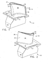
- Figure 1 is a perspective pressure (concave) side view of an engine turbine rotor blade that incorporates the airfoil of the blade of the invention
- Figure 2 is a second perspective suction (convex) side view of the engine turbine rotor blade of Figure 1 ;
- Figure 3 is a third perspective leading edge view of the engine turbine rotor blade of Figure 1 ;
- Figure 4 is a cutaway perspective view of the blade showing the blade cooling circuits in dotted lines;
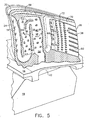
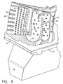
- Figure 5 is an enlarged cutaway perspective view similar in direction to that of Figure 1 ;
- Figure 6 is an enlarged cutaway perspective view similar in direction to that of Figure 2 ;
- FIG. 7 is a detailed pressure side view of the cooling circuits
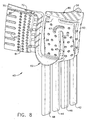
- FIG. 8 is a detailed suction side view of the cooling circuits
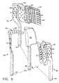
- Figure 9 is a pressure side exploded view of the cooling circuits of the invention.
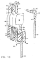
- Figure 10 is a suction side exploded view of the cooling circuits of the invention.
- Figure 11 is a pressure side view of the pressure side individual cooling circuit
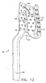
- Figure 12 is a suction side view of the pressure side individual cooling circuit
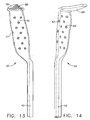
- Figure 13 is a suction side view of the suction side forward and tip plenum individual cooling circuit
- Figure 14 is a pressure side view of the suction side forward and tip plenum individual cooling circuit
- Figure 15 is a suction side view of a suction side aft, trailing edge, and tip flag cooling circuit
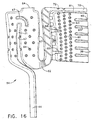
- Figure 16 is a pressure side view of a suction side aft, trailing edge, and tip flag cooling circuit
- Figure 17 is a pressure side view of a center body cooling circuit
- Figure 18 is a suction side view of a center body cooling circuit
- Figure 19 is a cross-sectional view of the blade of the invention taken along lines 19-19 of Figure 4 , viewed from the top at about 80% radial span;
- Figure 20 is a cross-sectional view of the blade of the invention taken along lines 20-20 of Figure 4 , viewed from the top at about 10% radial span.
- Figures 1, 2 and 3 disclose an aircraft jet engine turbine rotor blade 10 that includes a shank 12 and the airfoil 14 of the invention.
- the shank 12 includes a platform 16, which helps to radially contain the turbine airflow, and a blade root area 18 where the dovetail (not shown) would be machined, which in the case of the blade attaches it to a turbine rotor disc (not shown).
- the airfoil blade 14 has a first outer wall 20 a second outer wall 22 together defining an airfoil shape including a leading edge 24, a trailing edge 26, a pressure side 28 along the first outer wall 20, a suction side 30 along the second outer wall 22, a blade tip 32, a pressure side discharge trailing edge slot 38, and an airfoil/platform fillet 34.
- FIGS 4 , 5 and 6 provide respective views into the internal cooling circuits 40 of the blade airfoil 14.
- there are four distinct flow circuits each connected to a respective inlet extending through blade root 18, platform 16, and shank 12.
- this invention utilizes a cooling configuration that is fabricated as a single piece casting using a plurality of individual ceramic cores that are assembled and fastened into a single core. All the flow circuits 40 are embodied in this single assembly which is then used in a conventional wax pattern for processing with a conventional casting fabrication method.
- the internal cooling passages are shown in the reverse image schematic in Figure 7 for the pressure (concave) side 20 of the airfoil and in Figure 8 for the suction (convex) side 22 of the airfoil.
- the individual circuits 50, 52, 54, and 56 are shown in reverse image in Figures 9 through 18 .
- the pressure side flow circuit 56 is shown in Figures 11 and 12 .
- the suction side forward and tip plenum 58 flow circuit 50 is shown in Figures 13 and 14 .
- the suction side aft flow circuit 54 shown in Figures 15 and 16 , receives the cooling air from the suction side forward flow circuit exit 64 after it flows across the tip cap plenum 58.
- the center body circuit 52 forms a hollow center to minimize the blade airfoil weight while maintaining the required metal cross-sectional area for controlling the stress distribution in the airfoil.
- This center body circuit may use a small amount of cooling flow or no flow at all, depending on the specific design. Utilizing this assembled-cooling circuit technique allows the cooling passages to be completely independent or coupled together as the need arises.
- Turbine vanes and blades in accordance with the prior art typically utilize much thicker (low aspect ratio) cooling passages (e.g., about 0.5 to 1.5) that are subject to significant Coriolis and buoyancy effects on the internal heat transfer.
- the inventive blade 10 minimizes these effects by employing thin (high aspect ratio, e.g., about 2 to 10) channels in its multi-pass (e.g., about 1 to 3 passes) serpentine channels.
- having multiple walls allows the thicker inner walls (e.g., about 1.5 to 3 times thicker than the outer warmer walls) to remain much cooler (e.g., about 100 to 300 °F cooler) than the thin outer walls (which are about 0.015 to 0.020 inches thick).
- the thicker, cooler inner walls can carry the majority (e.g., about 1.5 to 5 times more than the thinner outer walls) of the mechanical loads on the blade and thus increase the stress rupture life of the blade.
- Utilizing pin fins 59 in the outer core cooling passages (as opposed to turbulators or trip-strips) allows a tailored thermal gradient between the cooler inner walls 82 and 83 and hotter outer walls 20 and 22, as shown in Figures 19 and 20 .
- the pressure side cooling circuit 56 is airflow independent of the other flow circuits. Air enters the inlet channel 48 (see Figure 4 ) and proceeds radially upwards though a thin serpentine cooling circuit 55 with pin fins 59 and half pin fins 47 to optimize the flow and heat transfer characteristics in the flow circuit.
- the thickness of the cooling channel can be on the order of about 0.030 inches. Before the airflow reaches the bank of pin fins 59, a portion of the flow can be bled off through an aerodynamically designed super-charger channel 57 which minimizes turning losses as it tangentially draws air into the turn.
- This super-charger circuit 57 specifically biases cool air to the hot outer wall of the leading edge 24 of the airfoil and greatly improves the back-flow margin of the blade (i.e., the ratio of inside pressure to outside pressure, which is a measure of propensity to ingest hot flow-path gases inside the turbine blade).
- the cross over channel is unique in that it provides a second flow circuit supplying cooling air to the forward feed channel 77. This further charges the pressure in this circuit to maintain the forward circuit backflow margin.
- An advantageous feature of the pressure side cooling circuit 56 is the specific combination placement of pin fins 59 and a turning vane 53 in the serpentine passage 55.
- the pins and turning vanes are placed to spread the flow of air through the circuit in such a way as to prevent separation of the air from the sidewalls. This maximizes the cooling effectiveness of the flow circuit while minimizing the corresponding pressure drop associated with separated and re-circulation regions.
- the classic separation zone downstream of the turning vane 53 along the cavity dividing rib 71 has been reduced by 75% by placement of the pin fins 59 to strategically re-direct the flow back to the cavity dividing rib 71.
- the separation zone along the cavity dividing rib 71 was minimized by utilizing 3-D computational fluid dynamics (CFD) modeling of the passage.
- CFD computational fluid dynamics
- the suction side forward cooling circuit 50 draws its cooling air from the inlet channel 42 and utilizes both full pin fins 49 and half pin fins 47 to optimize the flow and heat transfer characteristics in the flow circuit.
- the inventive blade 10 utilizes a flow circuit which allows the spent air to cool the tip 32 of the blade 10 and then join joint 64 to cool the remaining aft portions 54 of the blade 10, thus improving the thermal effectiveness of the blade.
- This invention is more advantageous than the prior art, which typically uses serpentine turns to cool the tip region of the blade. These serpentine turns can have significant recirculation zones with low heat transfer.
- the inventive blade suction side forward flow circuit 50 provides a quasi-independent flow circuit that is effectively a direct feed of air to cool the tip cap region 32 of the blade. After cooling the tip cap region 32, the spent air is then used to minimize the serpentine losses as it joins joint 64 with the suction side aft cooling circuit 54 to aid in cooling the trailing edge regions of the blade.
- the suction side aft cooing circuit 54 derives its feed air from the inlet channel 44. It utilizes many of the features of the pressure side circuit 56, including pin fins 69, half pins 47, and turning vane 67 with pin fin optimization for pressure drop and heat transfer. Unlike the prior art serpentine turns, the inventive blade thin outer core aspect ratio construction allows a unique aft serpentine bend 62 optimization at the hub of the blade.
- the aft serpentine circuit 54 utilizes conventional cross-over holes 66 to supply air to a pin fin bank 61, which then exits the spent air out of the trailing edge 26 of the airfoil.
- Conventional tip flags have turbulators that induce turbulence on the suction and pressure walls of the airfoil.
- Tip flag 70 is unique because this invention employs tip strip turbulators 72 on the top wall adjacent to the airfoil tip cap 32 aft region.
- the cooling of the tip flag region is enhanced by a factor of two on the top wall, while the pressure and suction sides of the airfoil are cooled both by convection to the tip flag cooling air and by conduction from the lower wall 81 which divides the pin fin bank 61 from the tip flag cavity 70.
- pin fin bank features are employed which also make the inventive blade more advantageous than the prior art.
- Straightening vanes 68 impede the tendency of the air to initially pass vertically between pin rows. This improves the airflow distribution in the pin bank 61, reduces flow separation, and minimizes low heat transfer regions caused by recirculation zones.
- the pin bank 61 is designed such that exactly two pin fins 63 are positioned between the trailing edge teardrops 60 and 65 which form the trailing edge slot exit flow dividers.
- This invention results in counter rotating canceling vortices at the exit of the pin bank. This produces a more uniform flow field than a "non-paired" pin distribution. These vortex pairs result in a higher total pressure distribution for the exiting flow at the exit slot 38 and a higher film effectiveness on the trailing edge slot 38, thus improving the temperature distribution at the hot trailing edge 26 of the blade airfoil 14.
- Figures 19 and 20 illustrate in cross-sectional views the relative wall thickness of the blade's exterior and interior structures and the location of the various cooling circuits relative to the exterior walls 20 and 22, to the internal walls 82 and 83, and to the leading and trailing edges 24 and 26.
- Figure 19 is a cross-sectional view taken near the blade tip 32 at about 80% radial span.
- Figure 20 is a cross-sectional view taken near the blade root 34 at about 10% radial span. It will be understood by those familiar with the turbine blade art, that the relative wall thicknesses make for a robust, multiple-walled, multi-pass, high cooling effectiveness, cooled turbine vane or blade designed for ease of manufacture which can be cast as a single piece using conventional casting methods.
Landscapes
- Engineering & Computer Science (AREA)
- Mechanical Engineering (AREA)
- General Engineering & Computer Science (AREA)
- Turbine Rotor Nozzle Sealing (AREA)
Claims (7)
- Aube de turbine refroidie par air, l'aube ayant une force de surface portante définie par une paroi côté aspiration convexe, une paroi côté pression concave, un bord d'attaque, un bord de fuite, une racine et une pointe, les parois, les bords, la racine et la pointe formant un intérieur pour recevoir des circuits de refroidissement de l'aube, l'aube de turbine comprenant : une pluralité de circuits de refroidissement indépendants dans ledit intérieur, au moins l'un desdits circuits de refroidissement étant positionné de manière à refroidir ladite paroi côté pression et au moins un autre desdits circuits de refroidissement étant positionné pour refroidir ladite paroi côté aspiration, ladite pluralité de circuits de refroidissement (50, 52, 54, 56) comprenant deux desdits circuits de refroidissement (50, 54) positionnés de manière à refroidir ladite paroi côté aspiration (22), un plus proche dudit bord d'attaque (24) et l'autre plus proche dudit bord de fuite (26) et caractérisée en ce que :ledit circuit de refroidissement (56) de la paroi côté pression comprend un passage en serpentin (55) ayant une pluralité d'ailettes à broches (59) et une pale rotative (53) ;ledit circuit de refroidissement (54) de la paroi côté aspiration plus proche dudit bord de fuite (26) comprenant une portion en serpentin (62) et une portion de banc de broches (61), ladite portion de banc de broches (61) ayant une pluralité de fentes en forme de larme (60, 65) formant des diviseurs d'écoulement d'air du bord de fuite (26) pour refroidir ledit bord de fuite (26).
- Aube de turbine selon la revendication 1, dans laquelle ladite pluralité de circuits de refroidissement (50, 52, 54, 56) comprend des entrées d'air individuelles respectives.
- Aube de turbine selon la revendication 1 ou 2, dans laquelle ladite pluralité de circuits de refroidissement (50, 52, 54, 56) sont interconnectés mécaniquement les uns aux autres.
- Aube de turbine selon la revendication 1, 2, ou 3, dans laquelle ladite pluralité de circuits de refroidissement (50, 52, 54, 56) comprennent au moins un circuit de refroidissement (52) positionné substantiellement au centre dudit intérieur.
- Aube de turbine selon la revendication 4, dans laquelle ledit au moins un circuit de refroidissement (52) positionné substantiellement au centre dudit intérieur comprend des parois (82, 83) ayant une plus grande épaisseur que les parois (20, 22) desdits circuits de refroidissement côté pression et côté aspiration (56, 50, 54).
- Aube de turbine selon la revendication 1, dans laquelle ledit circuit de refroidissement côté aspiration (50) plus proche du bord d'attaque (24) comprend une chambre (58) positionnée à côté de ladite pointe (32) pour refroidir ladite pointe (32).
- Aube de turbine selon la revendication 1, dans laquelle ladite portion de banc de broches (61) comprend une pluralité d'ailettes à broches (63), lesdites fentes en forme de larme (60, 65) ayant deux desdites ailettes à broches (63) entre des fentes adjacentes (60, 65).
Applications Claiming Priority (3)
| Application Number | Priority Date | Filing Date | Title |
|---|---|---|---|
| US992250 | 2001-11-14 | ||
| US09/992,250 US6974308B2 (en) | 2001-11-14 | 2001-11-14 | High effectiveness cooled turbine vane or blade |
| PCT/US2002/036199 WO2003042503A1 (fr) | 2001-11-14 | 2002-11-12 | Aube ou pale de turbine a gaz refroidi interne |
Publications (2)
| Publication Number | Publication Date |
|---|---|
| EP1444418A1 EP1444418A1 (fr) | 2004-08-11 |
| EP1444418B1 true EP1444418B1 (fr) | 2009-04-01 |
Family
ID=25538098
Family Applications (1)
| Application Number | Title | Priority Date | Filing Date |
|---|---|---|---|
| EP02797094A Expired - Lifetime EP1444418B1 (fr) | 2001-11-14 | 2002-11-12 | Aube ou pale de turbine a gaz refroidi interne |
Country Status (5)
| Country | Link |
|---|---|
| US (1) | US6974308B2 (fr) |
| EP (1) | EP1444418B1 (fr) |
| CA (1) | CA2467188C (fr) |
| DE (1) | DE60231823D1 (fr) |
| WO (1) | WO2003042503A1 (fr) |
Families Citing this family (182)
| Publication number | Priority date | Publication date | Assignee | Title |
|---|---|---|---|---|
| US6955523B2 (en) * | 2003-08-08 | 2005-10-18 | Siemens Westinghouse Power Corporation | Cooling system for a turbine vane |
| US7186084B2 (en) * | 2003-11-19 | 2007-03-06 | General Electric Company | Hot gas path component with mesh and dimpled cooling |
| EP1533481A3 (fr) * | 2003-11-19 | 2009-11-04 | General Electric Company | Composant pour guider des gaz chauds avec une structure de refroidissement réticulée comprenant des bosses |
| GB0405322D0 (en) * | 2004-03-10 | 2004-04-21 | Rolls Royce Plc | Impingement cooling arrangement |
| US7175391B2 (en) * | 2004-07-08 | 2007-02-13 | United Technologies Corporation | Turbine blade |
| US7448433B2 (en) * | 2004-09-24 | 2008-11-11 | Honeywell International Inc. | Rapid prototype casting |
| US7255535B2 (en) | 2004-12-02 | 2007-08-14 | Albrecht Harry A | Cooling systems for stacked laminate CMC vane |
| US7153096B2 (en) | 2004-12-02 | 2006-12-26 | Siemens Power Generation, Inc. | Stacked laminate CMC turbine vane |
| US7198458B2 (en) | 2004-12-02 | 2007-04-03 | Siemens Power Generation, Inc. | Fail safe cooling system for turbine vanes |
| US7156620B2 (en) * | 2004-12-21 | 2007-01-02 | Pratt & Whitney Canada Corp. | Internally cooled gas turbine airfoil and method |
| US7156619B2 (en) * | 2004-12-21 | 2007-01-02 | Pratt & Whitney Canada Corp. | Internally cooled gas turbine airfoil and method |
| US7217097B2 (en) * | 2005-01-07 | 2007-05-15 | Siemens Power Generation, Inc. | Cooling system with internal flow guide within a turbine blade of a turbine engine |
| US7438527B2 (en) * | 2005-04-22 | 2008-10-21 | United Technologies Corporation | Airfoil trailing edge cooling |
| US20070201980A1 (en) * | 2005-10-11 | 2007-08-30 | Honeywell International, Inc. | Method to augment heat transfer using chamfered cylindrical depressions in cast internal cooling passages |
| US7744347B2 (en) | 2005-11-08 | 2010-06-29 | United Technologies Corporation | Peripheral microcircuit serpentine cooling for turbine airfoils |
| US7296972B2 (en) * | 2005-12-02 | 2007-11-20 | Siemens Power Generation, Inc. | Turbine airfoil with counter-flow serpentine channels |
| US7303376B2 (en) * | 2005-12-02 | 2007-12-04 | Siemens Power Generation, Inc. | Turbine airfoil with outer wall cooling system and inner mid-chord hot gas receiving cavity |
| US7413403B2 (en) * | 2005-12-22 | 2008-08-19 | United Technologies Corporation | Turbine blade tip cooling |
| US7547191B2 (en) * | 2006-08-24 | 2009-06-16 | Siemens Energy, Inc. | Turbine airfoil cooling system with perimeter cooling and rim cavity purge channels |
| US7625178B2 (en) * | 2006-08-30 | 2009-12-01 | Honeywell International Inc. | High effectiveness cooled turbine blade |
| US7572102B1 (en) * | 2006-09-20 | 2009-08-11 | Florida Turbine Technologies, Inc. | Large tapered air cooled turbine blade |
| US7690894B1 (en) * | 2006-09-25 | 2010-04-06 | Florida Turbine Technologies, Inc. | Ceramic core assembly for serpentine flow circuit in a turbine blade |
| US8413709B2 (en) * | 2006-12-06 | 2013-04-09 | General Electric Company | Composite core die, methods of manufacture thereof and articles manufactured therefrom |
| US20080135721A1 (en) * | 2006-12-06 | 2008-06-12 | General Electric Company | Casting compositions for manufacturing metal casting and methods of manufacturing thereof |
| US7624787B2 (en) * | 2006-12-06 | 2009-12-01 | General Electric Company | Disposable insert, and use thereof in a method for manufacturing an airfoil |
| US7938168B2 (en) * | 2006-12-06 | 2011-05-10 | General Electric Company | Ceramic cores, methods of manufacture thereof and articles manufactured from the same |
| US7487819B2 (en) * | 2006-12-11 | 2009-02-10 | General Electric Company | Disposable thin wall core die, methods of manufacture thereof and articles manufactured therefrom |
| US8884182B2 (en) | 2006-12-11 | 2014-11-11 | General Electric Company | Method of modifying the end wall contour in a turbine using laser consolidation and the turbines derived therefrom |
| US7762774B2 (en) * | 2006-12-15 | 2010-07-27 | Siemens Energy, Inc. | Cooling arrangement for a tapered turbine blade |
| US7674093B2 (en) * | 2006-12-19 | 2010-03-09 | General Electric Company | Cluster bridged casting core |
| US8757974B2 (en) * | 2007-01-11 | 2014-06-24 | United Technologies Corporation | Cooling circuit flow path for a turbine section airfoil |
| US7866370B2 (en) * | 2007-01-30 | 2011-01-11 | United Technologies Corporation | Blades, casting cores, and methods |
| US20080199661A1 (en) * | 2007-02-15 | 2008-08-21 | Siemens Power Generation, Inc. | Thermally insulated CMC structure with internal cooling |
| US7967566B2 (en) * | 2007-03-08 | 2011-06-28 | Siemens Energy, Inc. | Thermally balanced near wall cooling for a turbine blade |
| US8257809B2 (en) | 2007-03-08 | 2012-09-04 | Siemens Energy, Inc. | CMC wall structure with integral cooling channels |
| US7722326B2 (en) * | 2007-03-13 | 2010-05-25 | Siemens Energy, Inc. | Intensively cooled trailing edge of thin airfoils for turbine engines |
| US7967563B1 (en) * | 2007-11-19 | 2011-06-28 | Florida Turbine Technologies, Inc. | Turbine blade with tip section cooling channel |
| US8257035B2 (en) * | 2007-12-05 | 2012-09-04 | Siemens Energy, Inc. | Turbine vane for a gas turbine engine |
| US10156143B2 (en) * | 2007-12-06 | 2018-12-18 | United Technologies Corporation | Gas turbine engines and related systems involving air-cooled vanes |
| US8177492B2 (en) * | 2008-03-04 | 2012-05-15 | United Technologies Corporation | Passage obstruction for improved inlet coolant filling |
| US8172533B2 (en) * | 2008-05-14 | 2012-05-08 | United Technologies Corporation | Turbine blade internal cooling configuration |
| JP5717627B2 (ja) | 2008-06-12 | 2015-05-13 | アルストム テクノロジー リミテッドALSTOM Technology Ltd | ガスタービンに用いられる翼ならびにこのような翼を鋳造技術により製造するための方法 |
| EP2143883A1 (fr) * | 2008-07-10 | 2010-01-13 | Siemens Aktiengesellschaft | Aube de turbine et moyau de coulée de fabrication |
| US20100014977A1 (en) * | 2008-07-15 | 2010-01-21 | Shattuck Colman D | Variable pitch aft propeller vane system |
| EP2163726A1 (fr) | 2008-09-11 | 2010-03-17 | Siemens Aktiengesellschaft | Aube de turbine dotée d'un rebord arrière modulaire et graduée |
| US8137068B2 (en) * | 2008-11-21 | 2012-03-20 | United Technologies Corporation | Castings, casting cores, and methods |
| EP2196625A1 (fr) | 2008-12-10 | 2010-06-16 | Siemens Aktiengesellschaft | Aube de turbine dotée d'un passage agencé dans une paroi de séparation et noyau de coulage associé |
| US8167558B2 (en) * | 2009-01-19 | 2012-05-01 | Siemens Energy, Inc. | Modular serpentine cooling systems for turbine engine components |
| US8167560B2 (en) * | 2009-03-03 | 2012-05-01 | Siemens Energy, Inc. | Turbine airfoil with an internal cooling system having enhanced vortex forming turbulators |
| US8087893B1 (en) * | 2009-04-03 | 2012-01-03 | Florida Turbine Technologies, Inc. | Turbine blade with showerhead film cooling holes |
| US8066485B1 (en) * | 2009-05-15 | 2011-11-29 | Florida Turbine Technologies, Inc. | Turbine blade with tip section cooling |
| GB0911753D0 (en) * | 2009-07-07 | 2009-08-19 | Rolls Royce Plc | Heat transfer passage |
| US20110204205A1 (en) * | 2010-02-25 | 2011-08-25 | Ahmed Kamel | Casting core for turbine engine components and method of making the same |
| US8535004B2 (en) * | 2010-03-26 | 2013-09-17 | Siemens Energy, Inc. | Four-wall turbine airfoil with thermal strain control for reduced cycle fatigue |
| EP2426317A1 (fr) | 2010-09-03 | 2012-03-07 | Siemens Aktiengesellschaft | Aube de turbine pour une turbine à gaz |
| US10060264B2 (en) | 2010-12-30 | 2018-08-28 | Rolls-Royce North American Technologies Inc. | Gas turbine engine and cooled flowpath component therefor |
| US9022736B2 (en) * | 2011-02-15 | 2015-05-05 | Siemens Energy, Inc. | Integrated axial and tangential serpentine cooling circuit in a turbine airfoil |
| US8915712B2 (en) * | 2011-06-20 | 2014-12-23 | General Electric Company | Hot gas path component |
| US8714927B1 (en) * | 2011-07-12 | 2014-05-06 | United Technologies Corporation | Microcircuit skin core cut back to reduce microcircuit trailing edge stresses |
| US8882461B2 (en) | 2011-09-12 | 2014-11-11 | Honeywell International Inc. | Gas turbine engines with improved trailing edge cooling arrangements |
| FR2986982B1 (fr) * | 2012-02-22 | 2024-07-05 | Snecma | Ensemble de noyau de fonderie pour la fabrication d'une aube de turbomachine, procede de fabrication d'une aube et aube associes |
| US8974182B2 (en) * | 2012-03-01 | 2015-03-10 | General Electric Company | Turbine bucket with a core cavity having a contoured turn |
| US9297261B2 (en) | 2012-03-07 | 2016-03-29 | United Technologies Corporation | Airfoil with improved internal cooling channel pedestals |
| US9200523B2 (en) | 2012-03-14 | 2015-12-01 | Honeywell International Inc. | Turbine blade tip cooling |
| US9388700B2 (en) | 2012-03-16 | 2016-07-12 | United Technologies Corporation | Gas turbine engine airfoil cooling circuit |
| US8985940B2 (en) * | 2012-03-30 | 2015-03-24 | Solar Turbines Incorporated | Turbine cooling apparatus |
| EP2844839A1 (fr) | 2012-04-23 | 2015-03-11 | General Electric Company | Profil aérodynamique de turbine à commande d'épaisseur de paroi locale |
| US9296039B2 (en) | 2012-04-24 | 2016-03-29 | United Technologies Corporation | Gas turbine engine airfoil impingement cooling |
| US9243502B2 (en) | 2012-04-24 | 2016-01-26 | United Technologies Corporation | Airfoil cooling enhancement and method of making the same |
| US9957817B2 (en) | 2012-07-03 | 2018-05-01 | United Technologies Corporation | Tip leakage flow directionality control |
| US9777582B2 (en) | 2012-07-03 | 2017-10-03 | United Technologies Corporation | Tip leakage flow directionality control |
| US9260972B2 (en) | 2012-07-03 | 2016-02-16 | United Technologies Corporation | Tip leakage flow directionality control |
| US9951629B2 (en) | 2012-07-03 | 2018-04-24 | United Technologies Corporation | Tip leakage flow directionality control |
| US9759072B2 (en) | 2012-08-30 | 2017-09-12 | United Technologies Corporation | Gas turbine engine airfoil cooling circuit arrangement |
| US20140219813A1 (en) * | 2012-09-14 | 2014-08-07 | Rafael A. Perez | Gas turbine engine serpentine cooling passage |
| US9115590B2 (en) | 2012-09-26 | 2015-08-25 | United Technologies Corporation | Gas turbine engine airfoil cooling circuit |
| US9267381B2 (en) | 2012-09-28 | 2016-02-23 | Honeywell International Inc. | Cooled turbine airfoil structures |
| US8936067B2 (en) * | 2012-10-23 | 2015-01-20 | Siemens Aktiengesellschaft | Casting core for a cooling arrangement for a gas turbine component |
| US9482101B2 (en) | 2012-11-28 | 2016-11-01 | United Technologies Corporation | Trailing edge and tip cooling |
| US9476308B2 (en) | 2012-12-27 | 2016-10-25 | United Technologies Corporation | Gas turbine engine serpentine cooling passage with chevrons |
| US10173932B1 (en) | 2012-12-31 | 2019-01-08 | General Electric Company | Disposable core die and method of fabricating a ceramic body |
| US9638057B2 (en) | 2013-03-14 | 2017-05-02 | Rolls-Royce North American Technologies, Inc. | Augmented cooling system |
| US10427213B2 (en) | 2013-07-31 | 2019-10-01 | General Electric Company | Turbine blade with sectioned pins and method of making same |
| US9695696B2 (en) | 2013-07-31 | 2017-07-04 | General Electric Company | Turbine blade with sectioned pins |
| US20160222795A1 (en) * | 2013-10-23 | 2016-08-04 | United Technologies Corporation | Turbine Airfoil Cooling Core Exit |
| US20160298465A1 (en) * | 2013-12-12 | 2016-10-13 | United Technologies Corporation | Gas turbine engine component cooling passage with asymmetrical pedestals |
| US9765642B2 (en) | 2013-12-30 | 2017-09-19 | General Electric Company | Interior cooling circuits in turbine blades |
| US9995149B2 (en) | 2013-12-30 | 2018-06-12 | General Electric Company | Structural configurations and cooling circuits in turbine blades |
| US20150300180A1 (en) * | 2014-04-22 | 2015-10-22 | United Technologies Corporation | Gas turbine engine turbine blade tip with coated recess |
| FR3021697B1 (fr) * | 2014-05-28 | 2021-09-17 | Snecma | Aube de turbine a refroidissement optimise |
| FR3022811B1 (fr) * | 2014-06-30 | 2016-10-14 | Snecma | Procede de fabrication d'un assemblage de noyaux pour la fabrication d'une aube |
| EP2993301B1 (fr) * | 2014-08-28 | 2024-01-17 | RTX Corporation | Structure de moteur à turbine à gaz, moteur à turbine à gaz et procédé pour conduire un réfrigérant à travers un trajet d'écoulement dans un moteur à turbine à gaz. |
| US10167726B2 (en) * | 2014-09-11 | 2019-01-01 | United Technologies Corporation | Component core with shaped edges |
| EP3048262A1 (fr) * | 2015-01-20 | 2016-07-27 | Alstom Technology Ltd | Paroi pour un canal de gaz chaud dans une turbine à gaz |
| EP3059394B1 (fr) * | 2015-02-18 | 2019-10-30 | Ansaldo Energia Switzerland AG | Aube de turbine et ensemble d'aubes de turbine |
| US10704397B2 (en) | 2015-04-03 | 2020-07-07 | Siemens Aktiengesellschaft | Turbine blade trailing edge with low flow framing channel |
| US10502066B2 (en) | 2015-05-08 | 2019-12-10 | United Technologies Corporation | Turbine engine component including an axially aligned skin core passage interrupted by a pedestal |
| US10323524B2 (en) * | 2015-05-08 | 2019-06-18 | United Technologies Corporation | Axial skin core cooling passage for a turbine engine component |
| FR3037830B1 (fr) * | 2015-06-29 | 2024-02-16 | Snecma | Ensemble de moulage d'une aube de turbomachine, comprenant une portion en relief de grande section |
| US9976424B2 (en) | 2015-07-02 | 2018-05-22 | General Electric Company | Turbine blade |
| US10184341B2 (en) * | 2015-08-12 | 2019-01-22 | United Technologies Corporation | Airfoil baffle with wedge region |
| GB201517187D0 (en) * | 2015-09-29 | 2015-11-11 | Rolls Royce Plc | Simulation of rotor-stator flow interaction |
| US10443398B2 (en) | 2015-10-15 | 2019-10-15 | General Electric Company | Turbine blade |
| US10370978B2 (en) | 2015-10-15 | 2019-08-06 | General Electric Company | Turbine blade |
| US10208605B2 (en) | 2015-10-15 | 2019-02-19 | General Electric Company | Turbine blade |
| US10174620B2 (en) | 2015-10-15 | 2019-01-08 | General Electric Company | Turbine blade |
| US10307816B2 (en) | 2015-10-26 | 2019-06-04 | United Technologies Corporation | Additively manufactured core for use in casting an internal cooling circuit of a gas turbine engine component |
| US9885243B2 (en) | 2015-10-27 | 2018-02-06 | General Electric Company | Turbine bucket having outlet path in shroud |
| US10508554B2 (en) | 2015-10-27 | 2019-12-17 | General Electric Company | Turbine bucket having outlet path in shroud |
| US10156145B2 (en) * | 2015-10-27 | 2018-12-18 | General Electric Company | Turbine bucket having cooling passageway |
| US10060269B2 (en) | 2015-12-21 | 2018-08-28 | General Electric Company | Cooling circuits for a multi-wall blade |
| US9976425B2 (en) | 2015-12-21 | 2018-05-22 | General Electric Company | Cooling circuit for a multi-wall blade |
| US10030526B2 (en) | 2015-12-21 | 2018-07-24 | General Electric Company | Platform core feed for a multi-wall blade |
| US9926788B2 (en) | 2015-12-21 | 2018-03-27 | General Electric Company | Cooling circuit for a multi-wall blade |
| US10119405B2 (en) | 2015-12-21 | 2018-11-06 | General Electric Company | Cooling circuit for a multi-wall blade |
| US10226812B2 (en) | 2015-12-21 | 2019-03-12 | United Technologies Corporation | Additively manufactured core for use in casting an internal cooling circuit of a gas turbine engine component |
| US9932838B2 (en) | 2015-12-21 | 2018-04-03 | General Electric Company | Cooling circuit for a multi-wall blade |
| US10053989B2 (en) | 2015-12-21 | 2018-08-21 | General Electric Company | Cooling circuit for a multi-wall blade |
| US9938836B2 (en) | 2015-12-22 | 2018-04-10 | General Electric Company | Turbine airfoil with trailing edge cooling circuit |
| US10450874B2 (en) * | 2016-02-13 | 2019-10-22 | General Electric Company | Airfoil for a gas turbine engine |
| US10208606B2 (en) | 2016-02-29 | 2019-02-19 | Solar Turbine Incorporated | Airfoil for turbomachine and airfoil cooling method |
| US10519779B2 (en) * | 2016-03-16 | 2019-12-31 | General Electric Company | Radial CMC wall thickness variation for stress response |
| CN108779678B (zh) * | 2016-03-22 | 2021-05-28 | 西门子股份公司 | 具有后缘框架特征的涡轮翼型件 |
| US10738622B2 (en) | 2016-08-09 | 2020-08-11 | General Electric Company | Components having outer wall recesses for impingement cooling |
| US10443397B2 (en) | 2016-08-12 | 2019-10-15 | General Electric Company | Impingement system for an airfoil |
| US10364685B2 (en) | 2016-08-12 | 2019-07-30 | Gneral Electric Company | Impingement system for an airfoil |
| US10408062B2 (en) | 2016-08-12 | 2019-09-10 | General Electric Company | Impingement system for an airfoil |
| US10436048B2 (en) | 2016-08-12 | 2019-10-08 | General Electric Comapny | Systems for removing heat from turbine components |
| US10227877B2 (en) | 2016-08-18 | 2019-03-12 | General Electric Company | Cooling circuit for a multi-wall blade |
| US10221696B2 (en) | 2016-08-18 | 2019-03-05 | General Electric Company | Cooling circuit for a multi-wall blade |
| US10267162B2 (en) | 2016-08-18 | 2019-04-23 | General Electric Company | Platform core feed for a multi-wall blade |
| US10208608B2 (en) | 2016-08-18 | 2019-02-19 | General Electric Company | Cooling circuit for a multi-wall blade |
| US10208607B2 (en) | 2016-08-18 | 2019-02-19 | General Electric Company | Cooling circuit for a multi-wall blade |
| FR3058917B1 (fr) * | 2016-11-18 | 2020-06-12 | Safran Aircraft Engines | Noyau complexe de fonderie pour une aube multi-cavites |
| FR3062675B1 (fr) * | 2017-02-07 | 2021-01-15 | Safran Helicopter Engines | Aube haute pression ventilee de turbine d'helicoptere comprenant un conduit amont et une cavite centrale de refroidissement |
| USD826277S1 (en) | 2017-03-07 | 2018-08-21 | Regal Beloit America, Inc. | Motor housing |
| US10508548B2 (en) * | 2017-04-07 | 2019-12-17 | General Electric Company | Turbine engine with a platform cooling circuit |
| US10422232B2 (en) | 2017-05-22 | 2019-09-24 | United Technologies Corporation | Component for a gas turbine engine |
| US10801724B2 (en) * | 2017-06-14 | 2020-10-13 | General Electric Company | Method and apparatus for minimizing cross-flow across an engine cooling hole |
| US10577944B2 (en) | 2017-08-03 | 2020-03-03 | General Electric Company | Engine component with hollow turbulators |
| US10590778B2 (en) | 2017-08-03 | 2020-03-17 | General Electric Company | Engine component with non-uniform chevron pins |
| US10641105B2 (en) * | 2017-08-08 | 2020-05-05 | United Technologies Corporation | Airfoil having forward flowing serpentine flow |
| US10718219B2 (en) | 2017-12-13 | 2020-07-21 | Solar Turbines Incorporated | Turbine blade cooling system with tip diffuser |
| US11274569B2 (en) | 2017-12-13 | 2022-03-15 | Pratt & Whitney Canada Corp. | Turbine shroud cooling |
| US10533454B2 (en) | 2017-12-13 | 2020-01-14 | Pratt & Whitney Canada Corp. | Turbine shroud cooling |
| US10570773B2 (en) * | 2017-12-13 | 2020-02-25 | Pratt & Whitney Canada Corp. | Turbine shroud cooling |
| US10502093B2 (en) * | 2017-12-13 | 2019-12-10 | Pratt & Whitney Canada Corp. | Turbine shroud cooling |
| US10655476B2 (en) | 2017-12-14 | 2020-05-19 | Honeywell International Inc. | Gas turbine engines with airfoils having improved dust tolerance |
| US10890074B2 (en) * | 2018-05-01 | 2021-01-12 | Raytheon Technologies Corporation | Coriolis optimized u-channel with platform core |
| US11015454B2 (en) * | 2018-05-01 | 2021-05-25 | Raytheon Technologies Corporation | Coriolis optimized U-channel with root flag |
| US10753210B2 (en) * | 2018-05-02 | 2020-08-25 | Raytheon Technologies Corporation | Airfoil having improved cooling scheme |
| US10907479B2 (en) * | 2018-05-07 | 2021-02-02 | Raytheon Technologies Corporation | Airfoil having improved leading edge cooling scheme and damage resistance |
| US10941663B2 (en) * | 2018-05-07 | 2021-03-09 | Raytheon Technologies Corporation | Airfoil having improved leading edge cooling scheme and damage resistance |
| US10787932B2 (en) | 2018-07-13 | 2020-09-29 | Honeywell International Inc. | Turbine blade with dust tolerant cooling system |
| US10989067B2 (en) | 2018-07-13 | 2021-04-27 | Honeywell International Inc. | Turbine vane with dust tolerant cooling system |
| US10669862B2 (en) | 2018-07-13 | 2020-06-02 | Honeywell International Inc. | Airfoil with leading edge convective cooling system |
| US11015457B2 (en) | 2018-10-01 | 2021-05-25 | Raytheon Technologies Corporation | Multi-walled airfoil core |
| FR3090040B1 (fr) * | 2018-12-12 | 2021-06-25 | Safran | Aube de turbomachine à refroidissement amélioré |
| EP3921516B1 (fr) * | 2019-02-08 | 2024-03-27 | RTX Corporation | Alimentation de refroidissement de bord de fuite d'aube de turbine et procédé correspondant d'utilisation |
| KR102161765B1 (ko) * | 2019-02-22 | 2020-10-05 | 두산중공업 주식회사 | 터빈용 에어포일, 이를 포함하는 터빈 |
| US11015455B2 (en) | 2019-04-10 | 2021-05-25 | Pratt & Whitney Canada Corp. | Internally cooled turbine blade with creep reducing divider wall |
| US11053803B2 (en) * | 2019-06-26 | 2021-07-06 | Raytheon Technologies Corporation | Airfoils and core assemblies for gas turbine engines and methods of manufacture |
| US11454133B2 (en) | 2019-10-25 | 2022-09-27 | General Electric Company | Coolant delivery via an independent cooling circuit |
| US11480070B2 (en) | 2019-10-25 | 2022-10-25 | General Electric Company | Coolant delivery via an independent cooling circuit |
| US11434767B2 (en) | 2019-10-25 | 2022-09-06 | General Electric Company | Coolant delivery via an independent cooling circuit |
| CN110700894B (zh) * | 2019-11-05 | 2024-10-22 | 北京全四维动力科技有限公司 | 燃气轮机的涡轮转子叶片及采用其的燃气轮机 |
| US11230929B2 (en) | 2019-11-05 | 2022-01-25 | Honeywell International Inc. | Turbine component with dust tolerant cooling system |
| US11952911B2 (en) * | 2019-11-14 | 2024-04-09 | Rtx Corporation | Airfoil with connecting rib |
| CN111022127B (zh) * | 2019-11-29 | 2021-12-03 | 大连理工大学 | 一种涡轮叶片尾缘曲线式排气劈缝结构 |
| EP3862537A1 (fr) * | 2020-02-10 | 2021-08-11 | General Electric Company Polska sp. z o.o. | Tuyère de turbine refoidie et segment d'aube de guidage de turbine |
| US11365645B2 (en) | 2020-10-07 | 2022-06-21 | Pratt & Whitney Canada Corp. | Turbine shroud cooling |
| US12006836B2 (en) * | 2021-07-02 | 2024-06-11 | Rtx Corporation | Cooling arrangement for gas turbine engine component |
| USD1091472S1 (en) * | 2021-08-05 | 2025-09-02 | Siemens Energy, Inc. | Bracket |
| US11913353B2 (en) | 2021-08-06 | 2024-02-27 | Rtx Corporation | Airfoil tip arrangement for gas turbine engine |
| GB202118069D0 (en) * | 2021-12-14 | 2022-01-26 | Rolls Royce Plc | Blower assembly |
| US20240044255A1 (en) * | 2022-08-02 | 2024-02-08 | Raytheon Technologies Corporation | Asymmetric heat transfer member fillet to direct cooling flow |
| KR102791087B1 (ko) * | 2022-11-10 | 2025-04-02 | 두산에너빌리티 주식회사 | 에어포일, 이를 포함하는 터빈 블레이드 및 가스 터빈 |
| EP4455450A1 (fr) | 2023-04-27 | 2024-10-30 | Doosan Enerbility Co., Ltd. | Procédé de fabrication d'une aube pour une turbine à gaz, aube pour une turbine à gaz et turbine à gaz |
| EP4455451A1 (fr) | 2023-04-27 | 2024-10-30 | Doosan Enerbility Co., Ltd. | Procédé de fabrication d'une aube pour une turbine à gaz, aube pour une turbine à gaz et turbine à gaz |
| KR102925417B1 (ko) * | 2024-01-16 | 2026-02-11 | 연세대학교 산학협력단 | 터빈 블레이드 및 이를 포함하는 가스 터빈 |
| USD1117049S1 (en) * | 2024-06-23 | 2026-03-10 | Naviga Wind Power Spólka Z Ograniczona Odpowiedzialnoscia | Rotor blade |
| US20260117660A1 (en) * | 2024-10-28 | 2026-04-30 | Doosan Enerbility Co., Ltd. | Airfoil, turbine blade including the airfoil, and gas turbine including the turbine blade |
Family Cites Families (31)
| Publication number | Priority date | Publication date | Assignee | Title |
|---|---|---|---|---|
| GB800414A (en) | 1955-12-22 | 1958-08-27 | Rolls Royce | Improvements in or relating to the manufacture of blades for rotary machines, for example compressors or turbines |
| US3533712A (en) | 1966-02-26 | 1970-10-13 | Gen Electric | Cooled vane structure for high temperature turbines |
| GB1257041A (fr) * | 1968-03-27 | 1971-12-15 | ||
| US3635586A (en) | 1970-04-06 | 1972-01-18 | Rolls Royce | Method and apparatus for turbine blade cooling |
| US3902820A (en) | 1973-07-02 | 1975-09-02 | Westinghouse Electric Corp | Fluid cooled turbine rotor blade |
| US4224011A (en) | 1977-10-08 | 1980-09-23 | Rolls-Royce Limited | Cooled rotor blade for a gas turbine engine |
| US4236870A (en) | 1977-12-27 | 1980-12-02 | United Technologies Corporation | Turbine blade |
| US4278400A (en) | 1978-09-05 | 1981-07-14 | United Technologies Corporation | Coolable rotor blade |
| US4474532A (en) | 1981-12-28 | 1984-10-02 | United Technologies Corporation | Coolable airfoil for a rotary machine |
| GB2121483B (en) | 1982-06-08 | 1985-02-13 | Rolls Royce | Cooled turbine blade for a gas turbine engine |
| US4514144A (en) | 1983-06-20 | 1985-04-30 | General Electric Company | Angled turbulence promoter |
| US4767268A (en) | 1987-08-06 | 1988-08-30 | United Technologies Corporation | Triple pass cooled airfoil |
| US4753575A (en) | 1987-08-06 | 1988-06-28 | United Technologies Corporation | Airfoil with nested cooling channels |
| US5813835A (en) | 1991-08-19 | 1998-09-29 | The United States Of America As Represented By The Secretary Of The Air Force | Air-cooled turbine blade |
| US5295530A (en) | 1992-02-18 | 1994-03-22 | General Motors Corporation | Single-cast, high-temperature, thin wall structures and methods of making the same |
| US5660524A (en) | 1992-07-13 | 1997-08-26 | General Electric Company | Airfoil blade having a serpentine cooling circuit and impingement cooling |
| JPH06137102A (ja) * | 1992-10-26 | 1994-05-17 | Mitsubishi Heavy Ind Ltd | ガスタービン中空動翼 |
| WO1994012768A2 (fr) * | 1992-11-24 | 1994-06-09 | United Technologies Corporation | Structure d'aube refroidissable |
| US5403159A (en) | 1992-11-30 | 1995-04-04 | United Technoligies Corporation | Coolable airfoil structure |
| US5328331A (en) | 1993-06-28 | 1994-07-12 | General Electric Company | Turbine airfoil with double shell outer wall |
| US5702232A (en) | 1994-12-13 | 1997-12-30 | United Technologies Corporation | Cooled airfoils for a gas turbine engine |
| US5626462A (en) | 1995-01-03 | 1997-05-06 | General Electric Company | Double-wall airfoil |
| US5591007A (en) | 1995-05-31 | 1997-01-07 | General Electric Company | Multi-tier turbine airfoil |
| US5820343A (en) | 1995-07-31 | 1998-10-13 | United Technologies Corporation | Airfoil vibration damping device |
| US5558497A (en) | 1995-07-31 | 1996-09-24 | United Technologies Corporation | Airfoil vibration damping device |
| US5772397A (en) | 1996-05-08 | 1998-06-30 | Alliedsignal Inc. | Gas turbine airfoil with aft internal cooling |
| US5601399A (en) | 1996-05-08 | 1997-02-11 | Alliedsignal Inc. | Internally cooled gas turbine vane |
| US6234753B1 (en) * | 1999-05-24 | 2001-05-22 | General Electric Company | Turbine airfoil with internal cooling |
| US6168381B1 (en) | 1999-06-29 | 2001-01-02 | General Electric Company | Airfoil isolated leading edge cooling |
| US6254334B1 (en) * | 1999-10-05 | 2001-07-03 | United Technologies Corporation | Method and apparatus for cooling a wall within a gas turbine engine |
| DE19963349A1 (de) * | 1999-12-27 | 2001-06-28 | Abb Alstom Power Ch Ag | Schaufel für Gasturbinen mit Drosselquerschnitt an Hinterkante |
-
2001
- 2001-11-14 US US09/992,250 patent/US6974308B2/en not_active Expired - Lifetime
-
2002
- 2002-11-12 WO PCT/US2002/036199 patent/WO2003042503A1/fr not_active Ceased
- 2002-11-12 DE DE60231823T patent/DE60231823D1/de not_active Expired - Lifetime
- 2002-11-12 CA CA002467188A patent/CA2467188C/fr not_active Expired - Fee Related
- 2002-11-12 EP EP02797094A patent/EP1444418B1/fr not_active Expired - Lifetime
Also Published As
| Publication number | Publication date |
|---|---|
| WO2003042503A1 (fr) | 2003-05-22 |
| CA2467188A1 (fr) | 2003-05-22 |
| DE60231823D1 (de) | 2009-05-14 |
| CA2467188C (fr) | 2008-10-07 |
| US20040076519A1 (en) | 2004-04-22 |
| US6974308B2 (en) | 2005-12-13 |
| EP1444418A1 (fr) | 2004-08-11 |
Similar Documents
| Publication | Publication Date | Title |
|---|---|---|
| EP1444418B1 (fr) | Aube ou pale de turbine a gaz refroidi interne | |
| US7862299B1 (en) | Two piece hollow turbine blade with serpentine cooling circuits | |
| US8562295B1 (en) | Three piece bonded thin wall cooled blade | |
| EP1008724B1 (fr) | Aube de moteur à turbine à gaz | |
| US5975850A (en) | Turbulated cooling passages for turbine blades | |
| JP4688758B2 (ja) | パターン冷却式タービン翼形部 | |
| JP4486216B2 (ja) | 翼形部の隔離前縁冷却 | |
| JP4576177B2 (ja) | 収束ピン冷却式翼形部 | |
| EP2204538B1 (fr) | Circuits de refroidissement de pale de turbine | |
| US7131818B2 (en) | Airfoil with three-pass serpentine cooling channel and microcircuit | |
| JP4659206B2 (ja) | 勾配付きフイルム冷却を備えるタービンノズル | |
| EP3063376B1 (fr) | Moteur à turbine à gaz comprenant des jets de refroidissement par impact obliques sur une surface suivis d'un agencement de chevrons | |
| EP3341567B1 (fr) | Profil aérodynamique de turbine à refroidissement interne doté d'élément de déplacement d'écoulement | |
| US7186082B2 (en) | Cooled rotor blade and method for cooling a rotor blade | |
| US20050031450A1 (en) | Microcircuit airfoil mainbody | |
| EP1088964A2 (fr) | Fente pour le refroidissement par impact du bord d'attaque d'une aube pour une turbomachine | |
| US8613597B1 (en) | Turbine blade with trailing edge cooling | |
| US10662778B2 (en) | Turbine airfoil with internal impingement cooling feature | |
| US8317474B1 (en) | Turbine blade with near wall cooling | |
| CA2456628A1 (fr) | Refroidissement a microcircuit pour extremites d'aubes de turbine | |
| US7665968B2 (en) | Cooled rotor blade | |
| CA2513036C (fr) | Canal de refroidissement de profil aerodynamique avec restriction d'ecoulement au bord de fuite | |
| US11236617B2 (en) | Blade comprising an improved cooling circuit | |
| JP5524137B2 (ja) | ガスタービン翼 | |
| US11162370B2 (en) | Actively cooled component |
Legal Events
| Date | Code | Title | Description |
|---|---|---|---|
| PUAI | Public reference made under article 153(3) epc to a published international application that has entered the european phase |
Free format text: ORIGINAL CODE: 0009012 |
|
| 17P | Request for examination filed |
Effective date: 20040604 |
|
| AK | Designated contracting states |
Kind code of ref document: A1 Designated state(s): AT BE BG CH CY CZ DE DK EE ES FI FR GB GR IE IT LI LU MC NL PT SE SK TR |
|
| 17Q | First examination report despatched |
Effective date: 20080611 |
|
| GRAP | Despatch of communication of intention to grant a patent |
Free format text: ORIGINAL CODE: EPIDOSNIGR1 |
|
| GRAS | Grant fee paid |
Free format text: ORIGINAL CODE: EPIDOSNIGR3 |
|
| GRAA | (expected) grant |
Free format text: ORIGINAL CODE: 0009210 |
|
| AK | Designated contracting states |
Kind code of ref document: B1 Designated state(s): DE FR GB |
|
| REG | Reference to a national code |
Ref country code: GB Ref legal event code: FG4D |
|
| REF | Corresponds to: |
Ref document number: 60231823 Country of ref document: DE Date of ref document: 20090514 Kind code of ref document: P |
|
| PLBE | No opposition filed within time limit |
Free format text: ORIGINAL CODE: 0009261 |
|
| STAA | Information on the status of an ep patent application or granted ep patent |
Free format text: STATUS: NO OPPOSITION FILED WITHIN TIME LIMIT |
|
| 26N | No opposition filed |
Effective date: 20100105 |
|
| PGFP | Annual fee paid to national office [announced via postgrant information from national office to epo] |
Ref country code: FR Payment date: 20121113 Year of fee payment: 11 |
|
| PGFP | Annual fee paid to national office [announced via postgrant information from national office to epo] |
Ref country code: GB Payment date: 20121025 Year of fee payment: 11 |
|
| GBPC | Gb: european patent ceased through non-payment of renewal fee |
Effective date: 20131112 |
|
| REG | Reference to a national code |
Ref country code: FR Ref legal event code: ST Effective date: 20140731 |
|
| PG25 | Lapsed in a contracting state [announced via postgrant information from national office to epo] |
Ref country code: GB Free format text: LAPSE BECAUSE OF NON-PAYMENT OF DUE FEES Effective date: 20131112 Ref country code: FR Free format text: LAPSE BECAUSE OF NON-PAYMENT OF DUE FEES Effective date: 20131202 |
|
| PGFP | Annual fee paid to national office [announced via postgrant information from national office to epo] |
Ref country code: DE Payment date: 20190131 Year of fee payment: 17 |
|
| REG | Reference to a national code |
Ref country code: DE Ref legal event code: R119 Ref document number: 60231823 Country of ref document: DE |
|
| PG25 | Lapsed in a contracting state [announced via postgrant information from national office to epo] |
Ref country code: DE Free format text: LAPSE BECAUSE OF NON-PAYMENT OF DUE FEES Effective date: 20200603 |
|
| P01 | Opt-out of the competence of the unified patent court (upc) registered |
Effective date: 20230525 |