EP1444713B2 - Leistungsschalter - Google Patents
Leistungsschalter Download PDFInfo
- Publication number
- EP1444713B2 EP1444713B2 EP02803738A EP02803738A EP1444713B2 EP 1444713 B2 EP1444713 B2 EP 1444713B2 EP 02803738 A EP02803738 A EP 02803738A EP 02803738 A EP02803738 A EP 02803738A EP 1444713 B2 EP1444713 B2 EP 1444713B2
- Authority
- EP
- European Patent Office
- Prior art keywords
- outflow
- flow
- deflecting device
- quenching gas
- axial direction
- Prior art date
- Legal status (The legal status is an assumption and is not a legal conclusion. Google has not performed a legal analysis and makes no representation as to the accuracy of the status listed.)
- Expired - Lifetime
Links
- 238000010791 quenching Methods 0.000 claims description 20
- 230000000171 quenching effect Effects 0.000 claims description 20
- 230000002349 favourable effect Effects 0.000 description 6
- 238000000034 method Methods 0.000 description 4
- 238000004519 manufacturing process Methods 0.000 description 3
- 238000003801 milling Methods 0.000 description 3
- 239000002775 capsule Substances 0.000 description 2
- 238000005266 casting Methods 0.000 description 2
- 239000004020 conductor Substances 0.000 description 2
- 230000007704 transition Effects 0.000 description 2
- 240000001439 Opuntia Species 0.000 description 1
- 235000004727 Opuntia ficus indica Nutrition 0.000 description 1
- 230000001154 acute effect Effects 0.000 description 1
- 230000015572 biosynthetic process Effects 0.000 description 1
- 238000010276 construction Methods 0.000 description 1
- 238000005553 drilling Methods 0.000 description 1
- 230000000694 effects Effects 0.000 description 1
- 239000012777 electrically insulating material Substances 0.000 description 1
- 238000009413 insulation Methods 0.000 description 1
- 230000003313 weakening effect Effects 0.000 description 1
Images



Classifications
-
- H—ELECTRICITY
- H01—ELECTRIC ELEMENTS
- H01H—ELECTRIC SWITCHES; RELAYS; SELECTORS; EMERGENCY PROTECTIVE DEVICES
- H01H33/00—High-tension or heavy-current switches with arc-extinguishing or arc-preventing means
- H01H33/70—Switches with separate means for directing, obtaining, or increasing flow of arc-extinguishing fluid
- H01H33/88—Switches with separate means for directing, obtaining, or increasing flow of arc-extinguishing fluid the flow of arc-extinguishing fluid being produced or increased by movement of pistons or other pressure-producing parts
-
- H—ELECTRICITY
- H01—ELECTRIC ELEMENTS
- H01H—ELECTRIC SWITCHES; RELAYS; SELECTORS; EMERGENCY PROTECTIVE DEVICES
- H01H33/00—High-tension or heavy-current switches with arc-extinguishing or arc-preventing means
- H01H33/70—Switches with separate means for directing, obtaining, or increasing flow of arc-extinguishing fluid
- H01H33/88—Switches with separate means for directing, obtaining, or increasing flow of arc-extinguishing fluid the flow of arc-extinguishing fluid being produced or increased by movement of pistons or other pressure-producing parts
- H01H2033/888—Deflection of hot gasses and arcing products
Definitions
- the invention relates to a circuit breaker with a movable contact piece in an axial direction and with a switching case in the axial direction moving quenching gas flow which is coaxially surrounded by a flow deflecting device in a lateral surface at least one outflow opening for deflecting at least a portion of Extinguishing gas flow in an outflow direction.
- Such a circuit breaker is for example from the Patent DE 199 53 560 C1 known.
- a circuit breaker is described, the interrupter unit is disposed within a capsule housing.
- the contact tube has outlet openings, from which the extinguishing gas emerges.
- the quenching gas exits into a space which is delimited by a flow-deflecting device.
- the local flow deflection device is essentially cylindrical and has discharge openings in its lateral surface.
- the quenching gas can escape from the space delimited by the flow-deflecting device and into which the volumetric gas-filled volume surrounding the breaker unit of the circuit breaker flows.
- Such a circuit breaker is also from the document JP 58 071 524 A known.
- deflecting hoods are assigned to the outflow openings. These deflecting hoods redirect the escaping extinguishing gas in an axial direction of the interrupter unit. This deflection is necessary to prevent direct flow of the encapsulating by the quenching gas. With such a flow there would be the danger of a weakening of a gas insulation.
- the assignment of the deflection hoods to the outflow openings represents a technically complex construction, because the deflecting hoods are assigned to each outflow opening individually and each deflecting hood is to be individually fastened to the flow deflecting device. Due to the relatively complicated arrangement of outflow openings and deflection hoods to each other, a simple production method, such as a casting process, for such an arrangement is not available.
- the present invention has the object, a circuit breaker of the type mentioned in such a way that the steering of the emerging from an outflow extinguishing gas is optimized.
- An advantageous embodiment may further provide that the flow-deflecting device has on the lateral surface a protrusion and / or a recess, on whose flanks the first and / or the second outflow opening are arranged.
- first and / or the second outflow direction are arranged perpendicular to the lateral surface areas directly surrounding the first and / or the second outflow opening.
- the survey / -en and / or the depression / -en ring-shaped and / or interrupted ring around the axial direction can further be provided.
- the survey / -en and / or the recess / -en extend substantially web-like or channel-like in the axial direction.
- the Indian FIG. 1 shown circuit breaker 100 has an encapsulating housing 101.
- the encapsulating housing 101 may be made of an electrically conductive material or of an electrically insulating material.
- an interrupter unit 102 of the circuit breaker 100 is arranged in the interior of the encapsulating housing 101.
- the encapsulating housing 101 is filled with an insulating gas, for example SF 6 .
- the interrupter unit 102 has a contact set 103.
- the contact set 103 has a fixed rated current contact 104 and a movable rated current contact 105.
- a fixed arc contact 106 and a movable arcing contact 107 are provided.
- Both the movable rated current contact 105 and the movable arcing contact 107 are movable in an axial direction.
- the lower half of the FIG. 1 shows the contact set 103 in the on state, the upper half of FIG. 1 shows the contact set 103 during a shutdown process.
- the movable arc contact 107 is of tubular design, so that during a switch-off process by a possibly burning arc 108 resulting extinguishing gas within the movable arc contact 107 from the switching path of the contact set 103 can be dissipated.
- outlet openings 109, 110 are provided, from which the quenching gas can escape into a space which is surrounded by a flow deflecting device 1.
- the arrangement of the flow deflector 1 is not limited to the range of the contact set 103 applied to the end of the movable arcing contact 107.
- such a flow-deflecting device can also be provided in the region of the fixed rated-current contact 104 in order to redirect the quenching gas flowing out in its direction there.
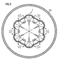
- FIG. 2 shows a cross section through the flow deflecting device 1 and the encapsulating 101.
- the flow-deflecting device 1 has a substantially circular cross-section. In their interior several tabs 4a, b, c, d, e, f are arranged. The tabs 4a, b, c, d, e, f serve both the mechanical support of the flow-deflecting device 1 on the interrupter unit 102 and the electrical contacting of the interrupter unit 102.
- the cylindrical base body of the flow-directing device 1 has a plurality of elevations 5a, b, c, d , e, f on.
- the elevations 5a, b, c, d, e, f are essentially formed by a widening of certain sections of the lateral surface of the cylindrical base body, with respect to the cylinder longitudinal axis 6 radially outward.
- the transitions from the original cylinder jacket to the radially outwardly flared regions are formed by oblique flanks 7a, b, c, d, e, f, g, h, i, j, k, l.
- the oblique flanks 7a, b, c, d, e, f, g, h, i, j, k, l each have outflow openings 10a, b, c, d, e, f, g, h, i, j, k , l for steering at least a portion of extinguishing gas generated in the interrupter unit 102.
- Each outflow opening 10a, b, c, d, e, f, g, h, i, j, k, l directs a portion of the quenching gas in an outflow direction.
- the outflow directions are each arranged such that they are directed perpendicular to the respective oblique flanks 7a, b, c, d, e, f, g, h, i, j, k, l.
- the outflow directions of respective proportions of the quenching gas are in the FIG. 3 symbolized by arrows. Due to the selected position of the outflow openings 10a, b, c, d, e, f, g, h, i, j, k, l to each other, each intersect the outflow directions of two opposing outflow openings adjacent surveys. It is thereby achieved that the extinguishing gas is conveniently mixed after passing through the respective outflow openings. This mixing is schematically in the FIG. 3 shown.
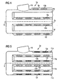
- FIG. 4 illustrated first variant of a flow deflecting device 1a shows a side view. Equally effective arrangements are provided in the figures with the same reference numerals.
- a connecting piece 16 is formed for connecting an electrical conductor.
- the first variant of the flow directing device 1a has a cylindrical basic shape, on the lateral surface of which a plurality of elevations 5a, b, c, d are arranged. The elevations 5a, b, c, d extend web-shaped along the axial direction.
- one end of the first variant of the flow-deflecting device 1a is closed in order to remove the extinguishing gas injected into the first variant of the flow-deflecting device 1a through outflow openings 10b, c, d, f arranged in the elevations 5a, b, c, d to let flow out.
- the elevations 5a, b, c, d have a truncated pyramidal outer shape.
- a plurality of outflow openings 10b, c, d, f are arranged in the side surfaces (flanks) of the truncated pyramids.
- the outflow openings 10b, c, d, f are formed in the first variant of the flow deflecting device 1a as a slot. It can be provided that in each case two outflow openings 10c, d of two adjacent elevations 5b, c are respectively assigned directly opposite one another and the outflow directions of the respectively directly assigned outflow openings 10c, d intersect.
- the in the FIG. 5 illustrated second variant of a flow deflector 1b has on its cylindrical surface a plurality of recesses 11a, b, c, d. In the flanks of the recesses 11a, b, c, d are further outflow openings 12a, b, c, d, e, f arranged.
- the outflow directions of the directly opposite in a recess 11c outflow openings 12d, e are directed so that they intersect.
- the in the FIG. 6 illustrated third variant of a flow deflector 1c shows, by way of example, further possible design variants of the elevations or depressions.
- the elevations or depressions can be arranged for example in a variety of different forms on the lateral surface of a flow deflecting device.
- the formation of the respective outflow openings can be very variable, for example, circular, oval or other suitable shapes and, for example, as a vertical or oblique bore / milling.
- this "bevel” causes the outflow openings to discharge the extinguishing gas into certain outflow directions independently of the design of the lateral surface.
- truncated pyramidal elevations or depressions and other forms can be used advantageously.
- Favorable forms are, for example: the shape of a spherical cap 13a, b, a tetrahedral stump 14 or an otherwise polygonal body 15. In order to obtain a favorable dielectric shape, the body edges and body edge transitions to other surfaces are rounded off.
Landscapes
- Circuit Breakers (AREA)
- Arc-Extinguishing Devices That Are Switches (AREA)
Applications Claiming Priority (3)
| Application Number | Priority Date | Filing Date | Title |
|---|---|---|---|
| DE10156535A DE10156535C1 (de) | 2001-11-14 | 2001-11-14 | Leistungsschalter |
| DE10156535 | 2001-11-14 | ||
| PCT/DE2002/004061 WO2003046939A1 (de) | 2001-11-14 | 2002-10-29 | Leistungsschalter |
Publications (3)
| Publication Number | Publication Date |
|---|---|
| EP1444713A1 EP1444713A1 (de) | 2004-08-11 |
| EP1444713B1 EP1444713B1 (de) | 2005-03-23 |
| EP1444713B2 true EP1444713B2 (de) | 2009-11-11 |
Family
ID=7706112
Family Applications (1)
| Application Number | Title | Priority Date | Filing Date |
|---|---|---|---|
| EP02803738A Expired - Lifetime EP1444713B2 (de) | 2001-11-14 | 2002-10-29 | Leistungsschalter |
Country Status (5)
| Country | Link |
|---|---|
| US (1) | US7022922B2 (ru) |
| EP (1) | EP1444713B2 (ru) |
| DE (2) | DE10156535C1 (ru) |
| RU (1) | RU2293393C2 (ru) |
| WO (1) | WO2003046939A1 (ru) |
Families Citing this family (19)
| Publication number | Priority date | Publication date | Assignee | Title |
|---|---|---|---|---|
| EP1403891B2 (de) † | 2002-09-24 | 2016-09-28 | ABB Schweiz AG | Leistungsschalter |
| DE502004004571D1 (de) * | 2004-06-07 | 2007-09-20 | Abb Technology Ag | Leistungsschalter |
| CN101120423B (zh) * | 2004-12-24 | 2010-06-23 | Abb技术有限公司 | 具有改进的断流容量的发电机开关 |
| RU2342729C1 (ru) * | 2004-12-24 | 2008-12-27 | Абб Текнолоджи Аг | Способ охлаждения выхлопного газа в электрическом выключателе и электрический выключатель |
| JP4806534B2 (ja) * | 2005-03-31 | 2011-11-02 | カヤバ工業株式会社 | クロージング加工方法及びクロージング加工機 |
| ATE458259T1 (de) * | 2005-09-26 | 2010-03-15 | Abb Technology Ag | Hochspannungsschalter mit verbesserter schaltleistung |
| DE102006031219A1 (de) * | 2006-06-30 | 2008-01-10 | Siemens Ag | Leistungsschalter mit einem Gehäuse |
| DE502006006123D1 (de) † | 2006-12-06 | 2010-03-25 | Abb Research Ltd | Hochspannungsschalter mit einem isoliergasgefüllten Metallbehälter |
| DE102007063424A1 (de) | 2007-12-19 | 2009-06-25 | Siemens Ag | Unterbrecheranordnung mit einem bewegbaren Schaltrohr |
| FR2966972B1 (fr) * | 2010-10-27 | 2013-07-19 | Areva T & D Sas | Appareillage electrique sous enveloppe metallique comportant au moins un capot pare-effluve assurant des echanges convectifs |
| DE102011083588A1 (de) * | 2011-09-28 | 2013-03-28 | Siemens Aktiengesellschaft | Anordnung aufweisend eine Leistungsschalterunterbrechereinheit |
| DE102012208140A1 (de) * | 2012-05-15 | 2013-11-21 | Siemens Aktiengesellschaft | Elektrische Kontaktanordnung |
| DE102013010124A1 (de) * | 2013-06-18 | 2014-12-18 | Abb Technology Ag | Schaltkammer für einen gasisolierten Leistungsschalter |
| EP3180598B1 (en) | 2014-08-15 | 2024-03-06 | Tenova Goodfellow Inc. | System and method for analyzing dusty industrial off-gas chemistry |
| FR3030869B1 (fr) * | 2014-12-19 | 2017-02-10 | Alstom Technology Ltd | Disjoncteur comprenant un capot d'echappement de gaz a ouverture obturable |
| KR101688950B1 (ko) * | 2015-01-22 | 2016-12-22 | 엘에스산전 주식회사 | 배선용 차단기 |
| WO2017162517A1 (en) * | 2016-03-24 | 2017-09-28 | Abb Schweiz Ag | Electrical circuit breaker device |
| WO2018066119A1 (ja) * | 2016-10-06 | 2018-04-12 | 株式会社 東芝 | ガス遮断器 |
| EP3503153B1 (en) * | 2017-12-22 | 2021-09-01 | ABB Power Grids Switzerland AG | Gas-insulated high or medium voltage circuit breaker |
Citations (9)
| Publication number | Priority date | Publication date | Assignee | Title |
|---|---|---|---|---|
| DE1889068U (de) † | 1964-01-18 | 1964-03-12 | Concordia Maschinen Und Elek Z | Rohrloeschkammer mit kuehlvorrichtung. |
| CH645753A5 (en) † | 1979-05-22 | 1984-10-15 | Sprecher & Schuh Ag | Gas-blast circuit breaker |
| EP0753873A1 (de) † | 1995-07-13 | 1997-01-15 | Siemens Aktiengesellschaft | Hochspannungs-Leistungsschalter mit einem Isolierstoffkörper |
| EP0836209A2 (de) † | 1996-10-09 | 1998-04-15 | Asea Brown Boveri AG | Leistungsschalter |
| EP0933795A2 (en) † | 1998-01-29 | 1999-08-04 | Kabushiki Kaisha Toshiba | Gas circuit breaker |
| EP0817228B1 (de) † | 1996-07-05 | 1999-12-08 | Asea Brown Boveri AG | Leistungsschalter |
| DE19850395A1 (de) † | 1998-11-02 | 2000-05-04 | Asea Brown Boveri | Leistungsschalter |
| DE19928078A1 (de) † | 1999-06-11 | 2000-12-14 | Siemens Ag | Hochspannungsleistungsschalter mit einem Abströmkanal |
| DE19928080C1 (de) † | 1999-06-11 | 2001-02-08 | Siemens Ag | Hochspannungsleistungsschalter mit einem Abströmkanal |
Family Cites Families (23)
| Publication number | Priority date | Publication date | Assignee | Title |
|---|---|---|---|---|
| US2511597A (en) * | 1947-04-30 | 1950-06-13 | Joseph P Marx | Muffler with cup-shaped baffle |
| SE372652B (ru) * | 1971-07-30 | 1974-12-23 | Magrini Fab Riun Scarpa | |
| DE2209287C3 (de) * | 1972-02-22 | 1974-12-12 | Siemens Ag, 1000 Berlin Und 8000 Muenchen | Elektrischer Druckgasschalter |
| US4000387A (en) * | 1974-05-13 | 1976-12-28 | Westinghouse Electric Corporation | Puffer-type gas circuit-interrupter |
| US4328403A (en) * | 1977-02-15 | 1982-05-04 | Westinghouse Electric Corp. | Single barrel puffer circuit interrupter |
| CH625908A5 (ru) * | 1978-03-30 | 1981-10-15 | Sprecher & Schuh Ag | |
| US4276456A (en) * | 1978-10-23 | 1981-06-30 | Westinghouse Electric Corp. | Double-flow puffer-type compressed-gas circuit-interrupter |
| US4291208A (en) * | 1978-11-24 | 1981-09-22 | Westinghouse Electric Corp. | Gas-insulated circuit-interrupter having improved insulating nozzle |
| CH643087A5 (en) * | 1979-11-30 | 1984-05-15 | Sprecher & Schuh Ag | Gas-blast circuit breaker |
| DE3107525C2 (de) * | 1980-02-28 | 1994-09-22 | Mitsubishi Electric Corp | Druckgas-Leistungsschalter |
| JPS5871524A (ja) * | 1981-06-23 | 1983-04-28 | 株式会社東芝 | パツフア形ガスしや断器 |
| EP0075668B1 (de) * | 1981-09-30 | 1987-01-07 | Sprecher Energie AG | Druckgasschalter |
| US4426561A (en) * | 1982-01-19 | 1984-01-17 | Westinghouse Electric Corp. | Puffer-type compressed-gas circuit-interrupter |
| JPS6020111A (ja) | 1983-07-14 | 1985-02-01 | Fuji Electric Corp Res & Dev Ltd | 距離測定装置 |
| SU1707641A1 (ru) * | 1989-11-09 | 1992-01-23 | Научно-исследовательский, проектно-конструкторский и технологический институт высоковольтного аппаратостроения Ленинградского производственного объединения "Электроаппарат" | Способ гашени дуги отключени в высоковольтном коммутационном аппарате и устройство дл его осуществлени |
| RU2121187C1 (ru) * | 1997-02-05 | 1998-10-27 | Российский Федеральный Ядерный Центр - Всероссийский Научно-Исследовательский Институт Экспериментальной Физики | Газонаполненный электрический выключатель |
| US6757009B1 (en) | 1997-06-11 | 2004-06-29 | Eaton Corporation | Apparatus for detecting the presence of an occupant in a motor vehicle |
| JP4172554B2 (ja) | 1998-03-12 | 2008-10-29 | 富士重工業株式会社 | ステレオカメラの調整装置 |
| DE19832709C5 (de) * | 1998-07-14 | 2006-05-11 | Siemens Ag | Hochspannungsleistungsschalter mit einer Unterbrechereinheit |
| DE19852653A1 (de) | 1998-11-16 | 2000-05-18 | Bosch Gmbh Robert | Vorrichtung zum Erfassen der Belegung eines Fahrzeugsitzes |
| JP3587506B2 (ja) | 1999-08-30 | 2004-11-10 | 富士重工業株式会社 | ステレオカメラの調整装置 |
| JP3261115B2 (ja) | 1999-09-22 | 2002-02-25 | 富士重工業株式会社 | ステレオ画像処理装置 |
| DE19953560C1 (de) * | 1999-11-03 | 2001-06-07 | Siemens Ag | Druckgas-Leistungsschalter |
-
2001
- 2001-11-14 DE DE10156535A patent/DE10156535C1/de not_active Expired - Fee Related
-
2002
- 2002-10-29 US US10/495,454 patent/US7022922B2/en not_active Expired - Fee Related
- 2002-10-29 EP EP02803738A patent/EP1444713B2/de not_active Expired - Lifetime
- 2002-10-29 DE DE50202588T patent/DE50202588D1/de not_active Expired - Lifetime
- 2002-10-29 RU RU2004117866/09A patent/RU2293393C2/ru not_active IP Right Cessation
- 2002-10-29 WO PCT/DE2002/004061 patent/WO2003046939A1/de not_active Ceased
Patent Citations (9)
| Publication number | Priority date | Publication date | Assignee | Title |
|---|---|---|---|---|
| DE1889068U (de) † | 1964-01-18 | 1964-03-12 | Concordia Maschinen Und Elek Z | Rohrloeschkammer mit kuehlvorrichtung. |
| CH645753A5 (en) † | 1979-05-22 | 1984-10-15 | Sprecher & Schuh Ag | Gas-blast circuit breaker |
| EP0753873A1 (de) † | 1995-07-13 | 1997-01-15 | Siemens Aktiengesellschaft | Hochspannungs-Leistungsschalter mit einem Isolierstoffkörper |
| EP0817228B1 (de) † | 1996-07-05 | 1999-12-08 | Asea Brown Boveri AG | Leistungsschalter |
| EP0836209A2 (de) † | 1996-10-09 | 1998-04-15 | Asea Brown Boveri AG | Leistungsschalter |
| EP0933795A2 (en) † | 1998-01-29 | 1999-08-04 | Kabushiki Kaisha Toshiba | Gas circuit breaker |
| DE19850395A1 (de) † | 1998-11-02 | 2000-05-04 | Asea Brown Boveri | Leistungsschalter |
| DE19928078A1 (de) † | 1999-06-11 | 2000-12-14 | Siemens Ag | Hochspannungsleistungsschalter mit einem Abströmkanal |
| DE19928080C1 (de) † | 1999-06-11 | 2001-02-08 | Siemens Ag | Hochspannungsleistungsschalter mit einem Abströmkanal |
Also Published As
| Publication number | Publication date |
|---|---|
| US7022922B2 (en) | 2006-04-04 |
| DE50202588D1 (de) | 2005-04-28 |
| RU2004117866A (ru) | 2006-01-10 |
| US20040256361A1 (en) | 2004-12-23 |
| DE10156535C1 (de) | 2003-06-26 |
| RU2293393C2 (ru) | 2007-02-10 |
| WO2003046939A1 (de) | 2003-06-05 |
| EP1444713A1 (de) | 2004-08-11 |
| EP1444713B1 (de) | 2005-03-23 |
Similar Documents
| Publication | Publication Date | Title |
|---|---|---|
| EP1444713B2 (de) | Leistungsschalter | |
| EP1768150B1 (de) | Hochspannungsschalter mit verbesserter Schaltleistung | |
| DE2443141C3 (de) | Vakuumschalter mit einem Vakuumgehäuse | |
| EP2396800B1 (de) | Schaltgeräteanordnung mit einer schaltstrecke | |
| DE4440323A1 (de) | Düse für einen Brennerkopf eines Plasmaspritzgeräts | |
| EP1403891B2 (de) | Leistungsschalter | |
| DE102012202406B4 (de) | Schaltgeräteanordnung | |
| DE60002432T2 (de) | Vakuumschaltvorrichtung | |
| EP3270403B1 (de) | Sicherung | |
| DE2438017B2 (de) | Druckgasschalter | |
| WO2013045233A1 (de) | Leistungsschalterunterbrechereinheit | |
| EP1691389B1 (de) | Schaltkammer für einen gasisolierten Hochspannungsschalter | |
| EP0532513B1 (de) | Kontaktanordnung für eine vakuumschaltröhre | |
| DE2118166C3 (de) | Unterbrecherkammer für einen elektrischen Druckgasschalter mit einer Blasdüse | |
| WO2012139916A1 (de) | Elektrisches schaltgerät | |
| WO2011035781A1 (de) | Abbrandelement zur anordnung an einem schaltkontakt eines leistungsschalters | |
| DE2710868A1 (de) | Autopneumatischer leistungsschalter mit isolierstoffduese | |
| EP0817228B1 (de) | Leistungsschalter | |
| EP0221838B1 (de) | Druckgasschalter | |
| EP0808004B1 (de) | Verfahren zur Löschung des Lichtbogens eines Netzfolgestromes in einer Funkenstrecke, sowie Funkenstreckenanordnung zur Durchführung des Verfahrens | |
| DE2647643C2 (de) | Druckgasschalter | |
| DE19802893A1 (de) | Vakuumschaltkammer mit ringförmigem Isolator | |
| DE19506057A1 (de) | Löschfunkenstreckenanordnung | |
| EP0173804B1 (de) | Druckgasschalter | |
| EP3576125B1 (de) | Hochspannungsleistungsschalter |
Legal Events
| Date | Code | Title | Description |
|---|---|---|---|
| PUAI | Public reference made under article 153(3) epc to a published international application that has entered the european phase |
Free format text: ORIGINAL CODE: 0009012 |
|
| 17P | Request for examination filed |
Effective date: 20040322 |
|
| AK | Designated contracting states |
Kind code of ref document: A1 Designated state(s): AT BE BG CH CY CZ DE DK EE ES FI FR GB GR IE IT LI LU MC NL PT SE SK TR |
|
| GRAP | Despatch of communication of intention to grant a patent |
Free format text: ORIGINAL CODE: EPIDOSNIGR1 |
|
| RBV | Designated contracting states (corrected) |
Designated state(s): CH DE FR LI |
|
| GRAS | Grant fee paid |
Free format text: ORIGINAL CODE: EPIDOSNIGR3 |
|
| GRAA | (expected) grant |
Free format text: ORIGINAL CODE: 0009210 |
|
| AK | Designated contracting states |
Kind code of ref document: B1 Designated state(s): CH DE FR LI |
|
| REG | Reference to a national code |
Ref country code: CH Ref legal event code: NV Representative=s name: SIEMENS SCHWEIZ AG Ref country code: CH Ref legal event code: EP |
|
| REF | Corresponds to: |
Ref document number: 50202588 Country of ref document: DE Date of ref document: 20050428 Kind code of ref document: P |
|
| PLBI | Opposition filed |
Free format text: ORIGINAL CODE: 0009260 |
|
| PLAX | Notice of opposition and request to file observation + time limit sent |
Free format text: ORIGINAL CODE: EPIDOSNOBS2 |
|
| 26 | Opposition filed |
Opponent name: ABB SCHWEIZ AG Effective date: 20051222 |
|
| ET | Fr: translation filed | ||
| PLAF | Information modified related to communication of a notice of opposition and request to file observations + time limit |
Free format text: ORIGINAL CODE: EPIDOSCOBS2 |
|
| PLBB | Reply of patent proprietor to notice(s) of opposition received |
Free format text: ORIGINAL CODE: EPIDOSNOBS3 |
|
| APBM | Appeal reference recorded |
Free format text: ORIGINAL CODE: EPIDOSNREFNO |
|
| APBP | Date of receipt of notice of appeal recorded |
Free format text: ORIGINAL CODE: EPIDOSNNOA2O |
|
| APAH | Appeal reference modified |
Free format text: ORIGINAL CODE: EPIDOSCREFNO |
|
| REG | Reference to a national code |
Ref country code: CH Ref legal event code: PCAR Free format text: SIEMENS SCHWEIZ AG;INTELLECTUAL PROPERTY FREILAGERSTRASSE 40;8047 ZUERICH (CH) |
|
| APBU | Appeal procedure closed |
Free format text: ORIGINAL CODE: EPIDOSNNOA9O |
|
| PUAH | Patent maintained in amended form |
Free format text: ORIGINAL CODE: 0009272 |
|
| STAA | Information on the status of an ep patent application or granted ep patent |
Free format text: STATUS: PATENT MAINTAINED AS AMENDED |
|
| 27A | Patent maintained in amended form |
Effective date: 20091111 |
|
| AK | Designated contracting states |
Kind code of ref document: B2 Designated state(s): CH DE FR LI |
|
| REG | Reference to a national code |
Ref country code: CH Ref legal event code: AEN Free format text: AUFRECHTERHALTUNG DES PATENTES IN GEAENDERTER FORM |
|
| PGFP | Annual fee paid to national office [announced via postgrant information from national office to epo] |
Ref country code: FR Payment date: 20121031 Year of fee payment: 11 |
|
| PGFP | Annual fee paid to national office [announced via postgrant information from national office to epo] |
Ref country code: CH Payment date: 20130110 Year of fee payment: 11 Ref country code: DE Payment date: 20121216 Year of fee payment: 11 |
|
| REG | Reference to a national code |
Ref country code: CH Ref legal event code: PL |
|
| PG25 | Lapsed in a contracting state [announced via postgrant information from national office to epo] |
Ref country code: LI Free format text: LAPSE BECAUSE OF NON-PAYMENT OF DUE FEES Effective date: 20131031 Ref country code: CH Free format text: LAPSE BECAUSE OF NON-PAYMENT OF DUE FEES Effective date: 20131031 |
|
| REG | Reference to a national code |
Ref country code: FR Ref legal event code: ST Effective date: 20140630 |
|
| REG | Reference to a national code |
Ref country code: DE Ref legal event code: R119 Ref document number: 50202588 Country of ref document: DE Effective date: 20140501 |
|
| PG25 | Lapsed in a contracting state [announced via postgrant information from national office to epo] |
Ref country code: DE Free format text: LAPSE BECAUSE OF NON-PAYMENT OF DUE FEES Effective date: 20140501 Ref country code: FR Free format text: LAPSE BECAUSE OF NON-PAYMENT OF DUE FEES Effective date: 20131031 |