EP1444966B1 - Dentalkopfeinheit zur Messung der Wurzelkanallänge und Halterung mit elektrischem Kontakt dafür - Google Patents
Dentalkopfeinheit zur Messung der Wurzelkanallänge und Halterung mit elektrischem Kontakt dafür Download PDFInfo
- Publication number
- EP1444966B1 EP1444966B1 EP03020880A EP03020880A EP1444966B1 EP 1444966 B1 EP1444966 B1 EP 1444966B1 EP 03020880 A EP03020880 A EP 03020880A EP 03020880 A EP03020880 A EP 03020880A EP 1444966 B1 EP1444966 B1 EP 1444966B1
- Authority
- EP
- European Patent Office
- Prior art keywords
- contact
- head unit
- contact holder
- cutting tool
- root canal
- Prior art date
- Legal status (The legal status is an assumption and is not a legal conclusion. Google has not performed a legal analysis and makes no representation as to the accuracy of the status listed.)
- Expired - Lifetime
Links
- 210000004262 dental pulp cavity Anatomy 0.000 title claims abstract description 28
- 238000005520 cutting process Methods 0.000 claims abstract description 29
- 238000005259 measurement Methods 0.000 description 12
- 239000000523 sample Substances 0.000 description 7
- 238000002560 therapeutic procedure Methods 0.000 description 5
- 239000004020 conductor Substances 0.000 description 2
- 238000004519 manufacturing process Methods 0.000 description 2
- 239000002184 metal Substances 0.000 description 2
- 238000003825 pressing Methods 0.000 description 2
- 201000004328 Pulpitis Diseases 0.000 description 1
- 206010037464 Pulpitis dental Diseases 0.000 description 1
- 238000004140 cleaning Methods 0.000 description 1
- 210000003074 dental pulp Anatomy 0.000 description 1
- 239000012811 non-conductive material Substances 0.000 description 1
- 210000003296 saliva Anatomy 0.000 description 1
- 229920003002 synthetic resin Polymers 0.000 description 1
- 239000000057 synthetic resin Substances 0.000 description 1
Images



Classifications
-
- A—HUMAN NECESSITIES
- A61—MEDICAL OR VETERINARY SCIENCE; HYGIENE
- A61C—DENTISTRY; APPARATUS OR METHODS FOR ORAL OR DENTAL HYGIENE
- A61C19/00—Dental auxiliary appliances
- A61C19/04—Measuring instruments specially adapted for dentistry
- A61C19/041—Measuring instruments specially adapted for dentistry for measuring the length of the root canal of a tooth
-
- A—HUMAN NECESSITIES
- A61—MEDICAL OR VETERINARY SCIENCE; HYGIENE
- A61C—DENTISTRY; APPARATUS OR METHODS FOR ORAL OR DENTAL HYGIENE
- A61C5/00—Filling or capping teeth
- A61C5/40—Implements for surgical treatment of the roots or nerves of the teeth; Nerve needles; Methods or instruments for medication of the roots
- A61C5/44—Means for controlling working depth, e.g. supports or boxes with depth-gauging means, stop positioners or files with adjustably-mounted handles
-
- A—HUMAN NECESSITIES
- A61—MEDICAL OR VETERINARY SCIENCE; HYGIENE
- A61C—DENTISTRY; APPARATUS OR METHODS FOR ORAL OR DENTAL HYGIENE
- A61C1/00—Dental machines for boring or cutting ; General features of dental machines or apparatus, e.g. hand-piece design
- A61C1/08—Machine parts specially adapted for dentistry
- A61C1/14—Tool-holders, i.e. operating tool holders, e.g. burr holders
Definitions
- the present invention relates to a dental head unit for root canal therapy and measurement of the root canal length, and a contact holder assembly for use with such a dental head unit.
- Pulpectomy has widely been performed for treatment of pulpitis, which includes removal of the dental pulp, enlargement and cleaning of the root canal.
- Various devices have been proposed for performing such a treatment, including hand reamers, engine reamers, and engine files.
- the endodontic handpiece for electrically driving a cutting tool, such as a reamer or a file, used for root canal therapy is schematically shown in Fig. 4.
- the endodontic handpiece includes handpiece body 1A generally in an elongated cylindrical form, and head unit 1B detachably threaded onto the handpiece body 1A.
- the handpiece body 1A accommodates therein a motor driven by, for example, an external power supply or a rechargeable battery. This motor is operated by pressing power switch 4 provided projecting on the handpiece body 1A in its distal portion.
- the head unit 1B includes neck section 2 and head section 3 integrally connected to the distal end of the neck section 2.
- Cutting tool 5 is detachably mounted on the head section 3 and driven by the motor for endodonic treatment.
- the same handpiece is also capable of precisely measuring the length of the root canal.
- handpieces that employ the cutting tool as a probe to enable measurement of the length of the root canal during the root canal therapy.
- JP-9-224961-A discloses a handpiece having a root canal length measurement function, which enables measurement of the root canal length while giving the root canal therapy.
- This handpiece has incorporated inside a signal circuit for sending measurement signals from a root canal length measurement circuit to a measurement probe mounted on a head provided at the tip of the handpiece, and the signal circuit is electrically connected to the measurement probe via a contact piece.
- the contact piece is provided on the lower surface of the head and supported so as to be rotatable vertically in the axial direction of the measurement probe. The contact piece holds the measurement probe between the tip portions thereof when rotated in the upward direction that makes contact with the measurement probe.
- the contact piece is made vertically rotatable on the lower surface of the head by pivotally connecting the contact piece to a separately provided contact plate, which requires bothersome production and assembly of these parts. Further, possibility of improper contact between the contact piece and the contact plate in the pivoting region cannot be eliminated.
- a dental head unit as defined in the preamble of claim 1 and a contact holder assembly for use with a dental head unit as defined in the preamble of claim 5 have become known from US-A-5 897 315.
- a dental head unit in accordance with the present invention has been defined in claim 1.
- a contact holder assembly in accordance with the present invention has been defined in claim 5.
- the contact is fixed to the contact holder, and is brought into or out of contact with the cutting tool simply by sliding the contact holder with respect to the neck section.
- a root canal length measuring circuit is not necessarily provided in the handpiece body, and production and assembly of the dental head unit per se is simplified.
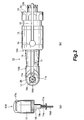
- dental head unit 10 includes head section 10B having sleeve 19 rotatably supported therein for detachably receiving cutting tool 18, and neck section 10A extending proximally from the head section 10B and having opening 33 in its proximal end for receiving a handpiece body for connection.
- the neck section 10A includes shaft 22 having gears 22a, 22b provided on both ends thereof, inner housing 14 rotatably accommodating the shaft 22 by means of distal and proximal bearings 23 and 24, outer housing 13 in which the inner housing 14 is inserted, and rear housing 25 connected onto the proximal end of the outer housing 13.
- the opening 33 is formed between the rear housing 25 and the inner housing 14.
- cutting tool 18 is rotatably supported in the head section 10B.
- the cutting tool 18 has grip 18c to be inserted into and held in the sleeve 19 of the head section 10B, and shank 18d extending downwardly from the grip 18c and used for enlarging the root canal in its tip portion.
- the grip 18c has reduced diameter portion 18b and notch 18a having a D-shaped section in its upper portion.
- the head section 10B includes sleeve 19 for detachably holding the grip 18c of the cutting tool 18.
- the sleeve 19 is rotatably supported in head housing 17 and head collar 26 by means of bearings 20a, 20b.
- the bearings 20a, 20b not only support the sleeve 19 rotatably, but also vertically position the sleeve 19 in place.
- gear 21 is integrally formed for meshing with the gear 22a on the shaft 22.
- projection 19a is projected on its inner surface for engagement with the notch 18a of the cutting tool 18. This mutual engagement of the projection 19a and the notch 18a ensures the sleeve 19 to rotate, when driven, with the cutting tool 18, without running idle alone.
- horizontal slit 17a is formed, into which latch 15 is inserted.
- the latch 15 has hook 15a in its tip, and is pivotally attached to the head housing 17 with fixture pin 16 threaded in a hole in the head housing 17.
- the latch 15 is pivoted horizontally around the fixture pin 16 to detachably engage the hook 15a with the reduced diameter portion 18b of the cutting tool 18 for holding the cutting tool 18 in place and preventing it from falling off.
- Contact holder 12 in a generally cylindrical form made of a non-conductive material, such as a synthetic resin, is provided on and around the outer housing 13 in an axially slidable manner.
- the contact holder 12 has urging member 12a such as a spring, and a ball 12b urged by the urging member 12a into engagement in one of slide grooves 13a, 13b, 13c provided in the outer surface of the outer housing 13.
- the contact holder 12 further has lead attachment 12d in the form of an aperture, into which contact pin 31 provided at an end of lead 32 is fit for providing electrical contact between contact 11 and a root canal length measuring device (not shown).
- Contact 11 made of an electrically conductive material, such as metal, is inserted from its proximal end into the contact holder 12 at a predetermined location, and fixed to the contact holder 12 by pressing annular fixture 11b into the contact holder 12 from the proximal end thereof, and fixing the fixture 11b to the proximal end of the contact 11.
- the fixture 11b is positioned so as not to be in contact with the outer surface of the outer housing 13.
- the contact holder 12 is fixed to the proximal end of the contact 11.
- the contact 11 has two rods 11a of a conductive material.
- the rods 11a extend straight distally from its proximal end, curved downward, and then forward, and in their distal end portions, slightly curved away from each other.
- the rods 11a are configured generally in a gentle curve so as to disengageably hold the cutting tool 18 between the rods 11a. That is, when shank 18d of the cutting tool 18 is held between the distal end portions of the rods 11a, the rods 11a are in close contact with the shank 18d from both sides, and when the shank 18d is not held between the rods 11a, the rods 11a are in close contact with each other.
- the proximal end portions of the rods 11a are arranged on opposite sides of the lead attachment 12d formed in the contact holder 12.
- the contact pin 31 is fit in the lead attachment 12d, the contact pin 31 is pressed between the two rods 11a to be in close contact therewith to provide electrical connection between the contact 11 and the contact pin 31, and thus the lead 32.
- the contact 11 is brought into or released from contact with the cutting tool 18 for providing or breaking electrical connection between the tool 18 and the contact 11.
- the contact holder assembly of the present invention includes the contact holder 12 and the contact 11 discussed above.
- the root canal length measuring device to be electrically connected to the contact 11 via the lead 32 is not shown in the drawings, but may be a conventional device.
- the device may have a body with a meter for indicating the change in the resistance, and two leads extending from the body and each having a connector at its free end.
- One of the connectors is connected with respect to the root canal forming tool or the probe, in this case the contact pin 31 as the connector is connected to the cutting tool 18 via the contact 11, and the other connector is connected to a metal part such as a saliva ejector.
- the device is set to indicate a predetermined range of resistance when the tip of the root canal forming tool reaches the apex foramen.
- the latch 15 is pivoted around the fixture pin 16 to disengage the hook 15a from the reduced diameter portion 18b of the cutting tool 18. This allows the grip 18c of the cutting tool 18 to be disengaged and removed from the sleeve 19.
- the contact 11 in the state shown in Figs. 1 and 2 (b) may be disengaged from the shank 18d of the cutting tool 18 into the state shown in Fig. 3, simply by sliding the contact holder 12 proximally with respect to the outer housing 13, which causes the contact 11 also to slide proximally to be disengaged from the shank 18d.
- the ball 12b in the contact holder 12 which has been fit in the distal slide groove 13a under the urging force of the urging means 12a, moves out of the groove 12a as the contact holder 12 is slid against the force of the urging means 12a, rolls along the slide groove 13b into the proximal slide groove 13c, and fits in the latter.
- the urging means 12a, the ball 12b, and the slide grooves 13a, 13b, 13c cooperate to limit the axial movement of the contact holder 12 within a predetermined range, and ensure to hold the contact holder 12 in the positions as shown in Figs. 1 and 3 when the contact holder 12 is not drawn to move in the axial direction.
- the contact holder 12 may be slid with the contact pin 31 fitting in the lead attachment 12d.
Landscapes
- Health & Medical Sciences (AREA)
- Life Sciences & Earth Sciences (AREA)
- Veterinary Medicine (AREA)
- Engineering & Computer Science (AREA)
- Biomedical Technology (AREA)
- Oral & Maxillofacial Surgery (AREA)
- Dentistry (AREA)
- Epidemiology (AREA)
- Animal Behavior & Ethology (AREA)
- General Health & Medical Sciences (AREA)
- Public Health (AREA)
- Biophysics (AREA)
- Neurology (AREA)
- Neurosurgery (AREA)
- Nuclear Medicine, Radiotherapy & Molecular Imaging (AREA)
- Surgery (AREA)
- Dental Tools And Instruments Or Auxiliary Dental Instruments (AREA)
Claims (5)
- Dentalkopfeinheit (10), mit der die Wurzelkanallänge eines Patienten gemessen werden kann, mit
einem Kopfabschnitt (10B) mit einer Hülse (19), die drehbar darin gelagert ist, um ein Fräswerkzeug (18) lösbar darin zu halten;
einem Halsabschnitt (10A), der sich in proximaler Richtung vom Kopfabschnitt (10B) erstreckt und ein proximales Ende zum Anschließen eines Handstückkörpers aufweist;
einem Kontakt (11), der lösbar mit dem Fräswerkzeug (18) in Kontakt treten kann, um eine elektrische Verbindung mit dem Fräswerkzeug (18) herzustellen, wenn ein Kontakt besteht; und
einem Kontakthalter (12), der an einem proximalen Ende des Kontaktes (11) fixiert ist;
dadurch gekennzeichnet, dass der Kontakthalter (12) relativ zum Halsabschnitt (10A) axial gleitend bewegbar ist, eine Leitungsbefestigung (12d) aufweist, an der eine Leitung (32) zum elektrischen Anschließen des Kontaktes (11) an eine Wurzelkanallängenmessvorrichtung lösbar befestigt ist, und am Halsabschnitt (10A) und um diesen herum vorgesehen ist. - Dentalkopfeinheit nach Anspruch 1, bei der der Kontakt (11) zwei Stäbe (11a) aufweist, die jeweils einen distalen Endabschnitt besitzen, der so ausgebildet ist, dass er das Fräswerkzeug (18) lösbar zwischen den beiden Stäben (11a) hält.
- Dentalkopfeinheit nach Anspruch 2, bei der die beiden Stäbe (11a) auf gegenüberliegenden Seiten der Leitungsbefestigung (12d9 angeordnet sind.
- Dentalkopfeinheit nach Anspruch 1, bei der die Leitungsbefestigung (12d) ein Loch ist, das im Kontakthalter (12) vorgesehen ist.
- Kontakthaltereinheit einer generell zylindrischen Form zur Verwendung mit einer Dentalkopfeinheit (10) nach Anspruch 1 mit einem Kopfabschnitt (10B) und einem Halsabschnitt (10A), die umfasst:einen Kontakt (11), der lösbar ein Fräswerkzeug (18) kontaktieren kann, das in einem Kopfabschnitt (10B) einer Dentalkopfeinheit (10) gehalten wird,um eine elektrische Verbindung mit dem Fräswerkzeug (18) herzustellen, wenn der Kontakt besteht; undeinen Kontakthalter (12), der an einem proximalen Ende des Kontaktes (11) fixiert ist;dadurch gekennzeichnet, dass der Kontakthalter (12) relativ zu einem Halsabschnitt (10A) der Dentalkopfeinheit (10) axial gleitend bewegbar ist, eine Leitungsbefestigung (12d) aufweist, an der eine Leitung (32) zum elektrischen Anschließen des Kontaktes (11) an eine Wurzelkanallängenmessvorrichtung lösbar befestigt ist, und am Halsabschnitt (10A) und um diesen herum anordbar ist.
Applications Claiming Priority (2)
| Application Number | Priority Date | Filing Date | Title |
|---|---|---|---|
| JP2003027811 | 2003-02-05 | ||
| JP2003027811A JP4065205B2 (ja) | 2003-02-05 | 2003-02-05 | 根管長測定可能な歯科用ヘッドユニット |
Publications (2)
| Publication Number | Publication Date |
|---|---|
| EP1444966A1 EP1444966A1 (de) | 2004-08-11 |
| EP1444966B1 true EP1444966B1 (de) | 2006-05-17 |
Family
ID=32652976
Family Applications (1)
| Application Number | Title | Priority Date | Filing Date |
|---|---|---|---|
| EP03020880A Expired - Lifetime EP1444966B1 (de) | 2003-02-05 | 2003-09-15 | Dentalkopfeinheit zur Messung der Wurzelkanallänge und Halterung mit elektrischem Kontakt dafür |
Country Status (5)
| Country | Link |
|---|---|
| US (1) | US7070411B2 (de) |
| EP (1) | EP1444966B1 (de) |
| JP (1) | JP4065205B2 (de) |
| AT (1) | ATE326193T1 (de) |
| DE (1) | DE60305287T2 (de) |
Families Citing this family (9)
| Publication number | Priority date | Publication date | Assignee | Title |
|---|---|---|---|---|
| US7758342B2 (en) | 2002-07-26 | 2010-07-20 | Aseptico, Inc. | Detecting and indicating a proximity of a dental instrument to a tooth apical foramen |
| EP1642547B1 (de) | 2004-09-30 | 2009-12-02 | W & H Dentalwerk Bürmoos GmbH | Dentales Handstück mit einer Wurzelkanallängen-Messfunktion |
| WO2006124247A1 (en) * | 2005-05-12 | 2006-11-23 | Pro-Dex, Inc. | Dental handpiece with removable apex finding electrode |
| US7628613B2 (en) * | 2005-07-28 | 2009-12-08 | Medic.Nrg Ltd. | Device for coupling dental instruments |
| JP4773860B2 (ja) * | 2006-03-31 | 2011-09-14 | 株式会社吉田製作所 | 根管長測定機能付き歯科用ハンドピース |
| DE502007003873D1 (de) * | 2007-09-27 | 2010-07-01 | W & H Dentalwerk Buermoos Gmbh | Dentales Handstück zur Behandlung von Wurzelkanälen |
| US20110300512A1 (en) * | 2009-02-19 | 2011-12-08 | Medicn.R.G. Ltd. | Apex locator mountable on a handpiece |
| KR101470426B1 (ko) * | 2014-08-11 | 2014-12-12 | 주식회사 올비트앤 | 근관 삽입 심도 감지 기능이 구비된 치아 근관 치료용 기구 |
| CN106725917A (zh) * | 2016-12-30 | 2017-05-31 | 佛山科学技术学院 | 一种根管治疗仪 |
Family Cites Families (4)
| Publication number | Priority date | Publication date | Assignee | Title |
|---|---|---|---|---|
| DE19520765B4 (de) | 1994-06-09 | 2004-07-08 | Kabushiki Kaisha Morita Seisakusho | Dental-Behandlungseinrichtung mit Wurzelkanallängen-Meßfunktion |
| JP3213539B2 (ja) * | 1996-02-22 | 2001-10-02 | 株式会社モリタ製作所 | 根管長測定機能付きハンドピース |
| US6520773B1 (en) | 2001-09-10 | 2003-02-18 | Joseph C. Weber | Endodontic file |
| US6845265B2 (en) * | 2002-07-26 | 2005-01-18 | Aseptico, Inc. | Systems and methods for locating a tooth's apical foramen |
-
2003
- 2003-02-05 JP JP2003027811A patent/JP4065205B2/ja not_active Expired - Fee Related
- 2003-09-11 US US10/659,274 patent/US7070411B2/en not_active Expired - Lifetime
- 2003-09-15 DE DE60305287T patent/DE60305287T2/de not_active Expired - Lifetime
- 2003-09-15 EP EP03020880A patent/EP1444966B1/de not_active Expired - Lifetime
- 2003-09-15 AT AT03020880T patent/ATE326193T1/de not_active IP Right Cessation
Also Published As
| Publication number | Publication date |
|---|---|
| DE60305287T2 (de) | 2006-09-21 |
| DE60305287D1 (de) | 2006-06-22 |
| JP2004236777A (ja) | 2004-08-26 |
| JP4065205B2 (ja) | 2008-03-19 |
| US20040152040A1 (en) | 2004-08-05 |
| EP1444966A1 (de) | 2004-08-11 |
| ATE326193T1 (de) | 2006-06-15 |
| US7070411B2 (en) | 2006-07-04 |
Similar Documents
| Publication | Publication Date | Title |
|---|---|---|
| JP3213539B2 (ja) | 根管長測定機能付きハンドピース | |
| US5060633A (en) | Laryngoscope blade | |
| US2588288A (en) | Dental light | |
| US5630812A (en) | Electrosurgical handpiece with locking nose piece | |
| US2911660A (en) | Power tooth brush | |
| US7597699B2 (en) | Motorized surgical handpiece | |
| US7070411B2 (en) | Dental head unit capable of measuring root canal length, and contact holder assembly therefor | |
| EP1913864A1 (de) | Beleuchtungsvorrichtung zur medizinischen Verwendung | |
| JP2006102497A (ja) | 根管長測定機能を有する歯科用ハンドピース | |
| US7121827B2 (en) | Endodontic instrument | |
| US4811736A (en) | Surgical drill and bur for use therewith | |
| US20040166464A1 (en) | Adapter for light emitting apparatus used in the medical field | |
| JP2002058681A (ja) | ハンドピース | |
| US20100112514A1 (en) | Wireless dental handpiece | |
| JP5785790B2 (ja) | 歯科用根管治療ハンドピース | |
| US5061178A (en) | Wax shaping tool | |
| JP4773860B2 (ja) | 根管長測定機能付き歯科用ハンドピース | |
| CN111000614A (zh) | 可视医用磨钻装置 | |
| US7476101B2 (en) | Dental handpiece with removable apex finding electrode | |
| CN1867300B (zh) | 具有单体件式主体的牙科用手持件——其具有在器械的机械传动机件和其头部之间配有弹性电连接机件 | |
| JP2021137526A (ja) | ファイルの往復動発生具およびファイル付きの往復動発生具 | |
| JP3805652B2 (ja) | 内視鏡鉗子口用アダプタ | |
| JP2013000212A (ja) | 歯科用根管治療ハンドピース | |
| JP4180046B2 (ja) | 歯科用ハンドピース | |
| KR102239528B1 (ko) | 탄력적 전기접속부를 갖는 치아 근관치료용 핸드피스 |
Legal Events
| Date | Code | Title | Description |
|---|---|---|---|
| PUAI | Public reference made under article 153(3) epc to a published international application that has entered the european phase |
Free format text: ORIGINAL CODE: 0009012 |
|
| AK | Designated contracting states |
Kind code of ref document: A1 Designated state(s): AT BE BG CH CY CZ DE DK EE ES FI FR GB GR HU IE IT LI LU MC NL PT RO SE SI SK TR |
|
| AX | Request for extension of the european patent |
Extension state: AL LT LV MK |
|
| 17P | Request for examination filed |
Effective date: 20050128 |
|
| AKX | Designation fees paid |
Designated state(s): AT CH DE FR GB IT LI |
|
| 17Q | First examination report despatched |
Effective date: 20050421 |
|
| RBV | Designated contracting states (corrected) |
Designated state(s): AT CH DE FR GB IT LI |
|
| GRAP | Despatch of communication of intention to grant a patent |
Free format text: ORIGINAL CODE: EPIDOSNIGR1 |
|
| GRAS | Grant fee paid |
Free format text: ORIGINAL CODE: EPIDOSNIGR3 |
|
| GRAA | (expected) grant |
Free format text: ORIGINAL CODE: 0009210 |
|
| AK | Designated contracting states |
Kind code of ref document: B1 Designated state(s): AT CH DE FR GB IT LI |
|
| REG | Reference to a national code |
Ref country code: GB Ref legal event code: FG4D |
|
| REG | Reference to a national code |
Ref country code: CH Ref legal event code: EP |
|
| REF | Corresponds to: |
Ref document number: 60305287 Country of ref document: DE Date of ref document: 20060622 Kind code of ref document: P |
|
| REG | Reference to a national code |
Ref country code: CH Ref legal event code: NV Representative=s name: KATZAROV S.A. |
|
| ET | Fr: translation filed | ||
| PLBE | No opposition filed within time limit |
Free format text: ORIGINAL CODE: 0009261 |
|
| STAA | Information on the status of an ep patent application or granted ep patent |
Free format text: STATUS: NO OPPOSITION FILED WITHIN TIME LIMIT |
|
| 26N | No opposition filed |
Effective date: 20070220 |
|
| PGFP | Annual fee paid to national office [announced via postgrant information from national office to epo] |
Ref country code: AT Payment date: 20080908 Year of fee payment: 6 Ref country code: FR Payment date: 20080829 Year of fee payment: 6 Ref country code: IT Payment date: 20080925 Year of fee payment: 6 |
|
| PGFP | Annual fee paid to national office [announced via postgrant information from national office to epo] |
Ref country code: GB Payment date: 20080922 Year of fee payment: 6 |
|
| PGFP | Annual fee paid to national office [announced via postgrant information from national office to epo] |
Ref country code: CH Payment date: 20081229 Year of fee payment: 6 |
|
| REG | Reference to a national code |
Ref country code: CH Ref legal event code: PL |
|
| GBPC | Gb: european patent ceased through non-payment of renewal fee |
Effective date: 20090915 |
|
| REG | Reference to a national code |
Ref country code: FR Ref legal event code: ST Effective date: 20100531 |
|
| PG25 | Lapsed in a contracting state [announced via postgrant information from national office to epo] |
Ref country code: AT Free format text: LAPSE BECAUSE OF NON-PAYMENT OF DUE FEES Effective date: 20090915 |
|
| PG25 | Lapsed in a contracting state [announced via postgrant information from national office to epo] |
Ref country code: FR Free format text: LAPSE BECAUSE OF NON-PAYMENT OF DUE FEES Effective date: 20090930 |
|
| PG25 | Lapsed in a contracting state [announced via postgrant information from national office to epo] |
Ref country code: LI Free format text: LAPSE BECAUSE OF NON-PAYMENT OF DUE FEES Effective date: 20090930 Ref country code: CH Free format text: LAPSE BECAUSE OF NON-PAYMENT OF DUE FEES Effective date: 20090930 |
|
| PG25 | Lapsed in a contracting state [announced via postgrant information from national office to epo] |
Ref country code: GB Free format text: LAPSE BECAUSE OF NON-PAYMENT OF DUE FEES Effective date: 20090915 |
|
| PG25 | Lapsed in a contracting state [announced via postgrant information from national office to epo] |
Ref country code: IT Free format text: LAPSE BECAUSE OF NON-PAYMENT OF DUE FEES Effective date: 20090915 |
|
| PGFP | Annual fee paid to national office [announced via postgrant information from national office to epo] |
Ref country code: DE Payment date: 20190903 Year of fee payment: 17 |
|
| REG | Reference to a national code |
Ref country code: DE Ref legal event code: R119 Ref document number: 60305287 Country of ref document: DE |
|
| PG25 | Lapsed in a contracting state [announced via postgrant information from national office to epo] |
Ref country code: DE Free format text: LAPSE BECAUSE OF NON-PAYMENT OF DUE FEES Effective date: 20210401 |