EP1445026B1 - Dispositif et procede de revetement par pulverisation - Google Patents
Dispositif et procede de revetement par pulverisation Download PDFInfo
- Publication number
- EP1445026B1 EP1445026B1 EP02778060A EP02778060A EP1445026B1 EP 1445026 B1 EP1445026 B1 EP 1445026B1 EP 02778060 A EP02778060 A EP 02778060A EP 02778060 A EP02778060 A EP 02778060A EP 1445026 B1 EP1445026 B1 EP 1445026B1
- Authority
- EP
- European Patent Office
- Prior art keywords
- pulse
- powder coating
- circuit
- voltage
- high voltage
- Prior art date
- Legal status (The legal status is an assumption and is not a legal conclusion. Google has not performed a legal analysis and makes no representation as to the accuracy of the status listed.)
- Expired - Lifetime
Links
- 238000000576 coating method Methods 0.000 title claims description 71
- 239000011248 coating agent Substances 0.000 title claims description 66
- 239000000843 powder Substances 0.000 title claims description 49
- 238000000034 method Methods 0.000 title claims description 6
- 239000000463 material Substances 0.000 claims description 24
- 230000010355 oscillation Effects 0.000 claims description 20
- 230000007274 generation of a signal involved in cell-cell signaling Effects 0.000 claims description 10
- 238000005507 spraying Methods 0.000 claims description 5
- 238000007600 charging Methods 0.000 claims description 2
- 150000002500 ions Chemical class 0.000 description 11
- 238000010586 diagram Methods 0.000 description 5
- 230000015556 catabolic process Effects 0.000 description 4
- 239000007921 spray Substances 0.000 description 4
- 230000005611 electricity Effects 0.000 description 3
- 238000002347 injection Methods 0.000 description 3
- 239000007924 injection Substances 0.000 description 3
- 230000007423 decrease Effects 0.000 description 2
- 230000003111 delayed effect Effects 0.000 description 2
- 230000007774 longterm Effects 0.000 description 2
- 239000003973 paint Substances 0.000 description 2
- 238000010422 painting Methods 0.000 description 2
- 238000009503 electrostatic coating Methods 0.000 description 1
- 230000007613 environmental effect Effects 0.000 description 1
- 238000010278 pulse charging Methods 0.000 description 1
- 239000002904 solvent Substances 0.000 description 1
- 230000003068 static effect Effects 0.000 description 1
Images


Classifications
-
- B—PERFORMING OPERATIONS; TRANSPORTING
- B05—SPRAYING OR ATOMISING IN GENERAL; APPLYING FLUENT MATERIALS TO SURFACES, IN GENERAL
- B05B—SPRAYING APPARATUS; ATOMISING APPARATUS; NOZZLES
- B05B5/00—Electrostatic spraying apparatus; Spraying apparatus with means for charging the spray electrically; Apparatus for spraying liquids or other fluent materials by other electric means
- B05B5/08—Plant for applying liquids or other fluent materials to objects
- B05B5/10—Arrangements for supplying power, e.g. charging power
-
- B—PERFORMING OPERATIONS; TRANSPORTING
- B05—SPRAYING OR ATOMISING IN GENERAL; APPLYING FLUENT MATERIALS TO SURFACES, IN GENERAL
- B05B—SPRAYING APPARATUS; ATOMISING APPARATUS; NOZZLES
- B05B5/00—Electrostatic spraying apparatus; Spraying apparatus with means for charging the spray electrically; Apparatus for spraying liquids or other fluent materials by other electric means
- B05B5/025—Discharge apparatus, e.g. electrostatic spray guns
- B05B5/03—Discharge apparatus, e.g. electrostatic spray guns characterised by the use of gas, e.g. electrostatically assisted pneumatic spraying
- B05B5/032—Discharge apparatus, e.g. electrostatic spray guns characterised by the use of gas, e.g. electrostatically assisted pneumatic spraying for spraying particulate materials
Definitions
- the present invention generally relates to a powder coating apparatus and method, and more particularly, to such a powder coating apparatus and method for spraying charged powder coating material to an object to be coated so as to apply it to the object while using static electricity.
- electrostatic powder coating as a painting or coating method of the environment-friendly and pollution-free type without using any solvent from the viewpoint of environmental protection.
- powder coating material is supplied from a paint tank through an injector to a spray gun, where it is injected or sprayed, together with a carrier air stream, to an object to be coated from a nozzle opening formed at a tip end of the spray gun.
- a high voltage is impressed upon a corona electrode which is provided at the tip end of the spray gun with the object to be coated being grounded, so that a corona discharge is generated from the electrode of the spray gun toward the object to be coated.
- the powder coating material injected from the nozzle opening passes through the neighborhood of the electrode, it is charged through its collision against ions generated by the corona discharge.
- the powder coating material thus charged is deposited on the surface of the object to be coated under the influence of the carrier air stream and electric forces generated along the electric lines of force.
- the generation of the corona discharge may be suppressed by a space charge of negative ions developed by the corona discharge itself, thus resulting in difficulty in providing a uniform corona discharge from the corona electrode.
- Document US-B1-6 227 465 describes a pulsing electrostatic atomizer which comprises a charge injection device injecting a net charge into a fluent material to thereby atomize the fluent material, and a power source powering the charge injection device.
- the power source is arranged to vary the net charge injected by the charge injection device cyclically in accordance with pattern of variation so that the net charge repeatedly increases to a higher value at or above a long-term breakdown value and repeatedly decreases to a lower value below the long-term breakdown value whereby corona-induced breakdown of the atomizer is reduced.
- Document JP 59 127 666 describes a sprayer for electrostatic charged granular body to obtain a stable quantity of electricity applied to a granular body. There is provided a DC high-voltage and a pulse high-voltage, wherein both voltages are impressed in a superimposed state onto a part to be charged with electricity.
- Document JP 2001 096201 describes an electrostatic coating device, wherein a high voltage pulse having a pulse width of less or equal 200 microseconds is applied between a coater and a work piece.
- the high-voltage pulse changes between 90 kV and 130 kV.
- JP 2001 096 201 serves also as basis for the preamble of claims 1 and 4.
- the present invention is intended to solve the problems as referred to above, and has its object to provide a powder coating apparatus and method which are capable of improving the efficiency of coating to an object to be coated as well as providing a coating film of excellent quality thereon.
- a powder coating apparatus for electrostatically coating a surface of an electrically grounded object to be coated with charged powder coating material, the apparatus comprising: a gun main body for spraying the powder coating material toward the object to be coated; at least one corona electrode arranged at a tip end of the gun main body for charging the powder coating material thus sprayed; and a pulse high-voltage generator for impressing a pulse-shaped high voltage upon the corona electrode to generate a corona discharge.
- a powder coating method for electrostatically coating a surface of an electrically grounded object to be coated with charged powder coating material, the method comprising the steps of: spraying the powder coating material from a gun main body toward the object to be coated; and impressing a pulse-shaped high voltage upon at least one corona electrode arranged at a tip end of the gun main body to generate a corona discharge thereby to charge the powder coating material thus sprayed.
- Fig. 1 shows the configuration of a powder coating apparatus according to a first embodiment of the present invention.
- the powder coating apparatus includes a gun main body 1 of a substantially cylindrical shape, with a powder conduit or passage 2 being formed on the central axis of the gun main body 1.
- the powder conduit 2 after being arranged along the outer periphery of a diffuser 3 to form a cylindrical shape, is connected with an annular nozzle opening 4 at a foremost portion of the gun main body 1.
- a plurality of corona electrodes 5 of the pin type, being held by the diffuser 3, are arranged inside the nozzle opening 4 in a manner as to protrude radially therefrom.
- the corona electrodes 5 are electrically connected with one another, and they are also connected with a pulse high-voltage generator 6.
- the circuit configuration of the pulse high-voltage generator 6 is illustrated in Fig. 2.
- the pulse high-voltage generator 6 includes a pulse signal generation circuit 7 that generates a pulse signal of a low voltage, and a high voltage impression circuit 8 that boosts the pulse signal, generated by the pulse signal generation circuit 7, to a high voltage so as to impress it upon the corona electrodes 5.
- the pulse signal generation circuit 7 has a pulse control circuit 11 and a reference voltage control circuit 12 connected with the pulse control circuit 11, to which the values of a pulse width T1 and a pulse interval T2 are input from the outside.
- a start signal is input from the outside to the reference voltage control circuit 12, together with the values of a peak voltage HV1 and a base voltage HV2 of a pulse-shaped high voltage to be impressed on the corona electrodes 5.
- the high voltage impression circuit 8 includes an oscillation DC power supply circuit 13, an oscillation circuit 14, a booster circuit 15 and a rectifier circuit 16, mutually connected in series with one another.
- An external AC power supply is connected with the oscillation DC power supply circuit 13.
- the rectifier circuit 16 of the high voltage impression circuit 8 is connected with the reference voltage control circuit 12 of the pulse signal generation circuit 7 through a discharge current control circuit 17, and a display device 18 is also connected with the reference voltage control circuit 12.
- a pulse signal S1 of a low voltage having these pulse widths T1 and pulse intervals T2 is formed in the pulse control circuit 11 of the pulse high-voltage generator 6, and output to the reference voltage control circuit 12.
- the pulse width T1 and the pulse interval T2 are set to values from several milliseconds to several hundred milliseconds, e.g., values of 5 to 500 milliseconds.
- the pulse signal S1 is shaped into a pulse signal S2 of a low voltage having a peak voltage V1 and a base voltage V2 corresponding to the values of the peak voltage HV1 and the base voltage HV2 input from the outside, respectively, in the reference voltage control circuit 12.
- the pulse signal S2 is output to the oscillation DC power supply circuit 13 of the high voltage impression circuit 8.
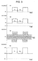
- the pulse signal S2 input from the reference voltage control circuit 12 is amplified by the oscillation DC power supply circuit 13, and then converted into a high frequency signal S3 by the oscillation circuit 14, as shown in Fig. 3.
- the high frequency signal S3 is input to the booster circuit 15, where it is boosted to a high voltage.
- the high frequency signal S3 is rectified by the rectifier circuit 16 to form a pulse-shaped high voltage signal S4 having the peak voltage HV1 and the base voltage HV2, as shown in Fig. 3.
- the peak voltage HV1 is set to a value of from 50 to 150 KV
- the base voltage HV2 is set to a value of from 0 to 50 KV, for instance. Since the pulse width T1 and the pulse interval T2 are set to large values such as from several milliseconds to several hundred milliseconds, it is possible to perform rectification in the general-purpose rectifier circuit 16 while reproducing the pulse waveform to a satisfactory extent.
- powder coating material is supplied to the powder conduit 2 together with carrier air, and it is injected or sprayed from the annular nozzle opening 4 in a forward direction.
- the powder coating material thus sprayed is charged with negative ions which are generated by the corona discharge developing from the corona electrodes 5 toward the object to be coated, and thereafter the powder coating material thus charged is directed toward the object to be coated so that it is deposited on the surface of the object to be coated.
- the corona discharge is intermittently generated from the corona electrodes 5 at a period of about several milliseconds to several hundred milliseconds, and hence negative ions produced by the corona discharge are not filled in a space between the gun main body 1 and the object to be coated. Therefore, the action of suppressing the corona discharge resulting from the space charge of the negative ions becomes limited, so that a uniform corona discharge is generated from the corona electrodes 5 during the impression of the high voltage signal S4. As a result, the efficiency of coating the object to be coated is improved.
- the impression of the pulse-shaped high voltage signal S4 serves to decrease a discharge current Id without lowering an impression voltage by properly adjusting the pulse width T1 and the pulse interval T2. Also, since a uniform corona discharge is generated from the corona electrodes 5, there takes place no local concentration of the discharge current Id, thus making a back ionization less apt to occur. Accordingly, it becomes possible to obtain a coating film with excellent quality.
- the discharge current Id accompanying the corona discharge from the corona electrodes 5 is monitored by means of the discharge current control circuit 17 through the rectifier circuit 16 of the high voltage impression circuit 8, so that it is compared with a cut-off current value Ith preset in the discharge current control circuit 17.
- the adjustment of the pulse width T1 and the pulse interval T2 of the pulse signal S2, i.e., the adjustment of the duty ratio thereof, is performed by means of the reference voltage control circuit 12 based on the result of the comparison in the discharge current control circuit 17 so that the discharge current Id does not exceed the cut-off current value Ith.
- the peak voltage HV1 and the base voltage HV2 of the high voltage signal S4 impressed upon the corona electrodes 5, the discharge current Id, the cut-off current value Ith and the like are displayed on the display device 18, whereby an operator can grasp the operating condition of the pulse high-voltage generator 6.
- the pulse width T1 and the pulse interval T2 are set to large values such as from several milliseconds to several hundred milliseconds, merely by boosting the pulse signal S2 of a low voltage generated in the pulse signal generation circuit 7 by means of the high voltage impression circuit 8, a pulse waveform is reproduced in the rectifier circuit 16 to a satisfactory extent to provide the pulse-shaped high voltage signal S4 which is to be impressed upon the corona electrodes 5. Therefore, pulse charging can be achieved with the single high voltage impression circuit 8 alone. Accordingly, it becomes possible to reduce the size and cost of the powder coating apparatus of high performance.
- the present invention is not limited to this, that is, the reference voltage control circuit 12 may adjust the values of the peak voltage V1 and the base voltage V2 of the pulse signal S2 so as not to allow the discharge current Id to exceed the preset cut-off current value Ith.
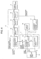
- the circuit configuration of a pulse high-voltage generator used in a second embodiment of the present invention is illustrated in Fig. 4.
- This pulse high-voltage generator is configured such that a mode selection circuit 31 is connected with the pulse signal generation circuit 7 in the pulse high-voltage generator in the first embodiment shown in Fig. 2.
- the mode selection circuit 31 stores in advance various combinations of a peak voltage HV1, a base voltage HV2, a pulse width T1 and a pulse interval T2, which are suitable for a plurality of coating modes, respectively, such as a thick-coating mode, a thin-coating mode, a through-coating mode for coating concave portions, a recoating mode for recoating a coating film, etc.
- a pulse width T1 and a pulse interval T2 stored therein are input to the pulse control circuit 11, and a peak voltage HV1 and a base voltage HV2 stored therein are input to the reference voltage control circuit 12, in response to the coating mode thus selected, and at the same time, a start signal is input from the mode selection circuit 31 to the reference voltage control circuit 12, so that a pulse-shaped high voltage signal S4 is impressed on the corona electrodes 5 thereby to electrostatically coat or paint the object to be coated, as described in the first embodiment.
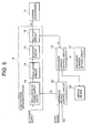
- a powder coating apparatus is generally similar in configuration to the powder coating apparatus of the first embodiment shown in Fig. 1, but it is different from the first embodiment in the internal configuration of a pulse high-voltage generator 6 connected with corona electrodes 5.
- the pulse high-voltage generator includes a high voltage impression circuit 8 for impressing a high voltage signal So upon the corona electrodes 5.
- the high voltage impression circuit 8 comprises an oscillation DC power supply circuit 13, an oscillation circuit 14, a booster circuit 15 and a rectifier circuit 16, which are mutually connected in series with one another, as in the one used in the first embodiment.
- An external AC power supply is connected with the oscillation DC power supply circuit 13.
- a discharge current control circuit 19 is connected with the rectifier circuit 16 of the high voltage impression circuit 8, and the oscillation DC power supply circuit 13 is connected with the discharge current control circuit 19 through a reference voltage control circuit 20.
- These circuit components serve to form a closed feedback circuit.
- a start signal is input from the outside to the reference voltage control circuit 20, together with a command value of a peak voltage HV of the high voltage signal So to be applied to the corona electrodes 5.
- a discharge current setting circuit 21 and a display device 22 are connected with the discharge current control circuit 19.
- the discharge current control circuit 19 includes a comparison circuit 23 that compares the mean value of a discharge current Io, which is obtained from the rectifier circuit 16 of the high voltage impression circuit 8 accompanying the impression of the high voltage signal So upon the corona electrodes 5, with a set value Is output from the discharge current setting circuit 21, and an amplifier circuit 24 connected with an output terminal of the comparison circuit 23.
- the amplifier circuit 24 has a gain Gv greater than an optimal gain Go of the feedback control in the closed feedback circuit.
- a low voltage signal Sv having a voltage corresponding to the command value of the peak voltage HV input from the outside is generated in the reference voltage control circuit 20 of the pulse high-voltage generator.
- the low voltage signal Sv is output to the oscillation DC power supply circuit 13 of the high voltage impression circuit 8 as an input signal si.
- the input signal Si is amplified by the oscillation DC power supply circuit 13, and then it is converted into a high frequency signal in the oscillation circuit 14.
- This high frequency signal is input to the booster circuit 15, where it is boosted to a high voltage, and thereafter it is rectified by the rectifier circuit 16 to form a high voltage signal So.
- a comparison between the mean value of the discharge current Io, obtained from the rectifier circuit 16 of the high voltage impression circuit 8 accompanying the impression of the high voltage signal So upon the corona electrodes 5, and the set value Is output from the discharge current setting circuit 21 is made by the comparison circuit 23 of the discharge current control circuit 19.
- a difference between them is amplified by the gain Gv in the amplifier circuit 24 to produce a differential signal Sd, which is in turn output to the reference voltage control circuit 20.
- the differential signal Sd is added to the low voltage signal Sv, which is generated corresponding to the command value of the peak voltage HV in the reference voltage control circuit 20, whereafter the signal in total is output to the oscillation DC power supply circuit 13 of the high voltage impression circuit 8 as an input signal Si.
- feedback control is carried out so as to make the mean value of the discharge current Io equal to the set value Is.
- the amplifier circuit 24 of the discharge current control circuit 19 has the gain Gv greater than the optimal gain Go of the feedback control, the input signal Si output from the reference voltage control circuit 20 to the oscillation DC power supply circuit 13 overshoots, whereby the feedback control is performed in an oscillation state.
- the high voltage signal So impressed on the corona electrodes 5 from the high voltage impression circuit 8 becomes to be a triangular wave-shaped pulse signal of a peak voltage HV of 20 to 100 KV and a period of 10 to 100 milliseconds for instance, as shown in Fig. 7.
- the corona discharge is intermittently generated from the corona electrodes 5, the negative ions produced due to the corona discharge are not filled in a space between the gun main body 1 and the object to be coated, and hence the action of suppressing the corona discharge resulting from the space charge of the negative ions becomes limited, whereby a uniform corona discharge is produced from the corona electrodes 5 during the impression of the high voltage signal So. Consequently, the coating efficiency to the object to be coated is improved.
- the generation of the uniform corona discharge serves to prevent local concentration of the discharge current Io, thus making it difficult for a back ionization to generate. Accordingly, a coating film with excellent quality can be obtained.
- the peak voltage HV of the high voltage signal So impressed upon the corona electrodes 5, the mean value and period of the discharge current Io, etc., are displayed on the display device 22 so that an operator can grasp the operating condition of the pulse high-voltage generator.
- a discharge current control circuit 19a of a configuration shown in Fig. 8 can be used instead of the discharge current control circuit 19.
- the discharge current control circuit 19a is further provided with a delay circuit 25 that, in the discharge current control circuit 19 of the third embodiment shown in Fig. 6, serves to delay an output from the comparison circuit 23 and then outputs it to the reference voltage control circuit 20. Since a differential signal Sd delayed in the delay circuit 25 is fedback to the high voltage impression circuit 8 through the reference voltage control circuit 20, the response speed of the feedback control is delayed to produce an oscillation state. Therefore, similar to the third embodiment using the discharge current control circuit 19 of Fig. 6, a triangular wave-shaped high voltage signal So is impressed from the high voltage impression circuit 8 upon the corona electrodes 5, whereby a corona discharge is intermittently generated by the corona electrodes 5.
- the gain of the amplifier circuit 24 may be an optimal gain Go of the feedback control, or it may be a gain Gv greater than the optimal gain Go.
- the present invention is not limited to a powder coating apparatus provided with a plurality of pin-type corona electrodes 5, as shown in Fig. 1, but can be similarly applied to a powder coating apparatus provided with a single corona electrode or linear electrode.
Landscapes
- Electrostatic Spraying Apparatus (AREA)
- Application Of Or Painting With Fluid Materials (AREA)
Claims (6)
- Appareil de revêtement par pulvérisation pour revêtir électrostatiquement une surface d'un objet électriquement mis à la masse à revêtir de matériau de revêtement par pulvérisation chargé, comprenant :un corps principal de canon (1) pour projeter le matériau de revêtement par pulvérisation vers ledit objet à revêtir ;caractérisé en ce queau moins une électrode corona (5) est agencée à une extrémité de pointe dudit corps principal de canon (1) pour charger ledit matériau de revêtement par pulvérisation ainsi projeté ; etun générateur d'impulsions haute tension (6) est prévu pour imprimer une haute tension en forme d'impulsion à ladite électrode corona (5) pour produire une décharge corona ;ledit générateur d'impulsions haute tension (6) comprendun circuit de génération de signal d'impulsion (7) pour produire un signal d'impulsion d'une basse tension ayant une largeur d'impulsion et un intervalle d'impulsion de plusieurs millisecondes à plusieurs centaines de millisecondes ;un circuit d'oscillation (14) pour convertir le signal d'impulsion produit par ledit circuit de génération de signaux d'impulsion (7) en un signal haute fréquence ;un circuit amplificateur (15) pour amplifier le signal haute fréquence converti par ledit circuit d'oscillation (14) en un signal haute tension ; etun circuit redresseur (16) pour redresser le signal haute tension amplifié par ledit circuit d'amplification (15) pour former ledit signal haute tension en forme d'impulsion ayant une largeur d'impulsion et un intervalle d'impulsion de plusieurs millisecondes à plusieurs centaines de millisecondes.
- Appareil de revêtement par pulvérisation selon la revendication 1, où ledit générateur d'impulsions haute tension (6) comprend :un circuit de commande de courant de décharge (17) pour comparer un courant de décharge qui s'écoule en accompagnant l'impression de la haute tension à ladite électrode corona (5), avec une valeur de courant de coupure préréglée ; etun circuit de commande de tension de référence (12) pour régler un facteur de marche du signal d'impulsion produit par ledit circuit de génération de signaux d'impulsion (7) sur la base du résultat de la comparaison dans ledit circuit de commande de courant de décharge (17) de telle manière que le courant de décharge ne dépasse pas ladite valeur de courant de coupure.
- Appareil de revêtement par pulvérisation selon la revendication 1, où ledit générateur d'impulsions haute tension (6) comprend :un circuit de commande de courant de décharge (17) pour comparer un courant de décharge, qui s'écoule en accompagnant l'impression de la haute tension à ladite électrode corona (5), avec une valeur de courant de coupure préréglée ; etun circuit de commande de tension de référence (12) pour régler une valeur de tension du signal d'impulsion produit par ledit circuit de génération de signaux d'impulsion (7) sur la base du résultat de la comparaison dans ledit circuit de commande de courant de décharge (17) de telle manière que le courant de décharge ne dépasse pas ladite valeur de courant de coupure.
- Procédé de revêtement par pulvérisation pour revêtir électrostatiquement une surface d'un objet électriquement mis à la masse à revêtir de matériau de revêtement par pulvérisation chargé,
ledit procédé comprenant les étapes consistant à :projeter le matériau de revêtement par pulvérisation d'un corps principal de canon (1) vers l'objet à revêtir ;caractérisé parimprimer une haute tension en forme d'impulsion à au moins une électrode corona (5) agencée à une extrémité de pointe dudit corps principal de canon (1) pour produire une décharge corona pour charger ainsi le matériau de revêtement par pulvérisation ainsi projeté,produire un signal d'impulsion d'une basse tension ayant une largeur d'impulsion et un intervalle d'impulsion de plusieurs millisecondes à plusieurs centaines de millisecondes ;convertir le signal d'impulsion en un signal haute fréquence ;amplifier le signal haute fréquence converti en un signal haute tensionredresser le signal haute tension pour former ledit signal haute tension en forme d'impulsion ayant une largeur d'impulsion et un intervalle d'impulsion de plusieurs millisecondes à plusieurs centaines de millisecondes. - Procédé de revêtement par pulvérisation selon la revendication 4, comprenant en outre les étapes consistant à :comparer un courant de décharge, qui s'écoule en accompagnant l'impression de la haute tension à ladite électrode corona (5), avec une valeur de courant de coupure préréglée ; etrégler un facteur de marche du signal d'impulsion sur la base du résultat de la comparaison de telle manière que le courant de décharge ne dépasse pas ladite valeur de courant de coupure.
- Procédé de revêtement par pulvérisation selon la revendication 4, comprenant en outre les étapes consistant àcomparer un courant de décharge, qui s'écoule en accompagnant l'impression de la haute tension à ladite électrode corona (5), avec une valeur de courant de coupure préréglée ; etajuster une valeur de tension du signal d'impulsion sur la base du résultat de la comparaison de telle manière que le courant de décharge ne dépasse pas ladite valeur de courant de coupure.
Applications Claiming Priority (5)
| Application Number | Priority Date | Filing Date | Title |
|---|---|---|---|
| JP2001351722A JP3774654B2 (ja) | 2001-11-16 | 2001-11-16 | 粉体塗装装置及び方法 |
| JP2001351722 | 2001-11-16 | ||
| JP2002189395 | 2002-06-28 | ||
| JP2002189395A JP2004025140A (ja) | 2002-06-28 | 2002-06-28 | 粉体塗装装置及び方法 |
| PCT/JP2002/011522 WO2003041867A1 (fr) | 2001-11-16 | 2002-11-05 | Dispositif et procede de revetement par pulverisation |
Publications (3)
| Publication Number | Publication Date |
|---|---|
| EP1445026A1 EP1445026A1 (fr) | 2004-08-11 |
| EP1445026A4 EP1445026A4 (fr) | 2005-07-20 |
| EP1445026B1 true EP1445026B1 (fr) | 2006-09-06 |
Family
ID=26624571
Family Applications (1)
| Application Number | Title | Priority Date | Filing Date |
|---|---|---|---|
| EP02778060A Expired - Lifetime EP1445026B1 (fr) | 2001-11-16 | 2002-11-05 | Dispositif et procede de revetement par pulverisation |
Country Status (6)
| Country | Link |
|---|---|
| US (1) | US7238394B2 (fr) |
| EP (1) | EP1445026B1 (fr) |
| CN (1) | CN1326626C (fr) |
| DE (1) | DE60214586T8 (fr) |
| TW (1) | TW574078B (fr) |
| WO (1) | WO2003041867A1 (fr) |
Families Citing this family (8)
| Publication number | Priority date | Publication date | Assignee | Title |
|---|---|---|---|---|
| CN101878070B (zh) * | 2007-11-30 | 2012-11-21 | Abb株式会社 | 静电涂装装置 |
| US8372478B1 (en) | 2009-07-15 | 2013-02-12 | Grace Engineering Corp. | Method for powder coating and decorative printing |
| JP5230041B1 (ja) | 2013-01-30 | 2013-07-10 | ランズバーグ・インダストリー株式会社 | 静電塗装機及び静電塗装方法 |
| CA3137668C (fr) | 2015-12-07 | 2023-08-29 | Hubbell Incorporated | Collier de serrage de boitier electrique |
| WO2017096740A1 (fr) * | 2015-12-09 | 2017-06-15 | Ac (Macao Commercial Offshore) Limited | Appareil de lavage sous pression amélioré à mode d'impulsion de suralimentation |
| JP6587189B2 (ja) * | 2016-09-08 | 2019-10-09 | パナソニックIpマネジメント株式会社 | 電圧印加装置、及び放電装置 |
| CN107930878A (zh) * | 2017-12-18 | 2018-04-20 | 天长市金陵电子有限责任公司 | 一种脉冲静电喷涂机 |
| CN112517260A (zh) * | 2020-12-11 | 2021-03-19 | 江门市博涂环保机电科技有限公司 | 一种脉冲静电喷涂装置及其喷涂工艺 |
Family Cites Families (10)
| Publication number | Priority date | Publication date | Assignee | Title |
|---|---|---|---|---|
| JPS5117235A (en) * | 1974-08-04 | 1976-02-12 | Senichi Masuda | Seidenfuntaitochakusochi |
| JPS59127666A (ja) * | 1983-01-08 | 1984-07-23 | Hitachi Plant Eng & Constr Co Ltd | 静電粒体散布機 |
| US4745520A (en) * | 1986-10-10 | 1988-05-17 | Ransburg Corporation | Power supply |
| DE4232026C2 (de) * | 1992-09-24 | 1996-10-24 | Wagner Int | Elektrostatische Beschichtungspistole und Verfahren zum Erzeugen einer Hochspannung |
| JP3018807B2 (ja) | 1993-01-20 | 2000-03-13 | トヨタ自動車株式会社 | 消耗電極式パルスアーク溶接装置 |
| JPH1160759A (ja) | 1997-08-25 | 1999-03-05 | Sekisui Chem Co Ltd | コロナ放電処理方法 |
| US6227465B1 (en) * | 1998-10-30 | 2001-05-08 | Charged Injection Corporation | Pulsing electrostatic atomizer |
| JP2001096201A (ja) * | 1999-09-30 | 2001-04-10 | Trinity Ind Corp | 静電塗布装置 |
| US6552504B2 (en) | 2000-08-25 | 2003-04-22 | Thomson Licensing Sa | Deflection circuit with a feedback controlled capacitive transformation |
| JP4679004B2 (ja) | 2000-09-26 | 2011-04-27 | 新明和工業株式会社 | アーク蒸発源装置、その駆動方法、及びイオンプレーティング装置 |
-
2002
- 2002-11-05 EP EP02778060A patent/EP1445026B1/fr not_active Expired - Lifetime
- 2002-11-05 US US10/493,382 patent/US7238394B2/en not_active Expired - Lifetime
- 2002-11-05 WO PCT/JP2002/011522 patent/WO2003041867A1/fr not_active Ceased
- 2002-11-05 CN CNB028227077A patent/CN1326626C/zh not_active Expired - Lifetime
- 2002-11-05 DE DE60214586T patent/DE60214586T8/de not_active Expired - Fee Related
- 2002-11-13 TW TW91133270A patent/TW574078B/zh active
Also Published As
| Publication number | Publication date |
|---|---|
| DE60214586D1 (de) | 2006-10-19 |
| DE60214586T2 (de) | 2007-05-16 |
| US7238394B2 (en) | 2007-07-03 |
| DE60214586T8 (de) | 2007-10-31 |
| EP1445026A1 (fr) | 2004-08-11 |
| CN1638876A (zh) | 2005-07-13 |
| EP1445026A4 (fr) | 2005-07-20 |
| TW200300366A (en) | 2003-06-01 |
| CN1326626C (zh) | 2007-07-18 |
| WO2003041867A1 (fr) | 2003-05-22 |
| US20040255865A1 (en) | 2004-12-23 |
| TW574078B (en) | 2004-02-01 |
Similar Documents
| Publication | Publication Date | Title |
|---|---|---|
| US4343828A (en) | Electrodynamic painting system and method | |
| EP2576077B1 (fr) | Appareil de peinture électrostatique et procédé électrostatique | |
| JPS637824B2 (fr) | ||
| EP1445026B1 (fr) | Dispositif et procede de revetement par pulverisation | |
| JP5390259B2 (ja) | 静電塗装装置及び塗装方法 | |
| JP3774654B2 (ja) | 粉体塗装装置及び方法 | |
| JPS63258669A (ja) | 静電塗装装置の動作制御法 | |
| JP5784884B2 (ja) | 静電塗装装置および静電塗装方法 | |
| JP2001096201A (ja) | 静電塗布装置 | |
| JP5758590B2 (ja) | 静電塗装装置 | |
| CA2311210A1 (fr) | Appareil de revetement par pulverisation | |
| JP2004148239A (ja) | 外部帯電式静電塗装スプレーガン | |
| JP5633990B2 (ja) | 静電塗装装置 | |
| JPS56155661A (en) | Generation of static electricity and apparatus therefor | |
| JP2012161757A (ja) | 静電塗装装置 | |
| JP2004025140A (ja) | 粉体塗装装置及び方法 | |
| JP2002355582A (ja) | 静電塗装装置 | |
| RU2086312C1 (ru) | Способ электростатического напыления порошковых покрытий и устройство для его осуществления | |
| JPS5933489Y2 (ja) | 静電式粉体塗装ガン | |
| JP2002292311A (ja) | 粉体塗装装置及び方法 | |
| JPH07328492A (ja) | 静電塗装方法および装置 | |
| JP2023016116A (ja) | 絶縁体の塗装方法および塗装装置 | |
| SU634796A1 (ru) | Устройство дл распылени лакокрасочного материала в электрическом поле | |
| KR20030052751A (ko) | 아연도금용 고전압 코로나 제어장치 및 방법 | |
| JPS5874168A (ja) | 静電塗装方法 |
Legal Events
| Date | Code | Title | Description |
|---|---|---|---|
| PUAI | Public reference made under article 153(3) epc to a published international application that has entered the european phase |
Free format text: ORIGINAL CODE: 0009012 |
|
| 17P | Request for examination filed |
Effective date: 20040426 |
|
| AK | Designated contracting states |
Kind code of ref document: A1 Designated state(s): AT BE BG CH CY CZ DE DK EE ES FI FR GB GR IE IT LI LU MC NL PT SE SK TR |
|
| A4 | Supplementary search report drawn up and despatched |
Effective date: 20050608 |
|
| GRAP | Despatch of communication of intention to grant a patent |
Free format text: ORIGINAL CODE: EPIDOSNIGR1 |
|
| GRAS | Grant fee paid |
Free format text: ORIGINAL CODE: EPIDOSNIGR3 |
|
| GRAA | (expected) grant |
Free format text: ORIGINAL CODE: 0009210 |
|
| AK | Designated contracting states |
Kind code of ref document: B1 Designated state(s): DE GB IT |
|
| PG25 | Lapsed in a contracting state [announced via postgrant information from national office to epo] |
Ref country code: IT Free format text: LAPSE BECAUSE OF FAILURE TO SUBMIT A TRANSLATION OF THE DESCRIPTION OR TO PAY THE FEE WITHIN THE PRESCRIBED TIME-LIMIT;WARNING: LAPSES OF ITALIAN PATENTS WITH EFFECTIVE DATE BEFORE 2007 MAY HAVE OCCURRED AT ANY TIME BEFORE 2007. THE CORRECT EFFECTIVE DATE MAY BE DIFFERENT FROM THE ONE RECORDED. Effective date: 20060906 |
|
| REG | Reference to a national code |
Ref country code: GB Ref legal event code: FG4D |
|
| REF | Corresponds to: |
Ref document number: 60214586 Country of ref document: DE Date of ref document: 20061019 Kind code of ref document: P |
|
| PLBE | No opposition filed within time limit |
Free format text: ORIGINAL CODE: 0009261 |
|
| STAA | Information on the status of an ep patent application or granted ep patent |
Free format text: STATUS: NO OPPOSITION FILED WITHIN TIME LIMIT |
|
| 26N | No opposition filed |
Effective date: 20070607 |
|
| GBPC | Gb: european patent ceased through non-payment of renewal fee |
Effective date: 20061206 |
|
| PG25 | Lapsed in a contracting state [announced via postgrant information from national office to epo] |
Ref country code: GB Free format text: LAPSE BECAUSE OF NON-PAYMENT OF DUE FEES Effective date: 20061206 |
|
| PGFP | Annual fee paid to national office [announced via postgrant information from national office to epo] |
Ref country code: IT Payment date: 20081125 Year of fee payment: 7 |
|
| PGFP | Annual fee paid to national office [announced via postgrant information from national office to epo] |
Ref country code: DE Payment date: 20090130 Year of fee payment: 7 |
|
| PG25 | Lapsed in a contracting state [announced via postgrant information from national office to epo] |
Ref country code: DE Free format text: LAPSE BECAUSE OF NON-PAYMENT OF DUE FEES Effective date: 20100601 |
|
| PG25 | Lapsed in a contracting state [announced via postgrant information from national office to epo] |
Ref country code: IT Free format text: LAPSE BECAUSE OF NON-PAYMENT OF DUE FEES Effective date: 20091105 |