EP1445075B1 - méthode pour surveiller un robot et robot muni de moyens de surveillance - Google Patents
méthode pour surveiller un robot et robot muni de moyens de surveillance Download PDFInfo
- Publication number
- EP1445075B1 EP1445075B1 EP04001285.8A EP04001285A EP1445075B1 EP 1445075 B1 EP1445075 B1 EP 1445075B1 EP 04001285 A EP04001285 A EP 04001285A EP 1445075 B1 EP1445075 B1 EP 1445075B1
- Authority
- EP
- European Patent Office
- Prior art keywords
- measurement
- measured
- industrial robot
- robot
- values
- Prior art date
- Legal status (The legal status is an assumption and is not a legal conclusion. Google has not performed a legal analysis and makes no representation as to the accuracy of the status listed.)
- Expired - Lifetime
Links
Images


Classifications
-
- B—PERFORMING OPERATIONS; TRANSPORTING
- B25—HAND TOOLS; PORTABLE POWER-DRIVEN TOOLS; MANIPULATORS
- B25J—MANIPULATORS; CHAMBERS PROVIDED WITH MANIPULATION DEVICES
- B25J9/00—Program-controlled manipulators
- B25J9/16—Program controls
- B25J9/1674—Program controls characterised by safety, monitoring, diagnostic
-
- G—PHYSICS
- G05—CONTROLLING; REGULATING
- G05B—CONTROL OR REGULATING SYSTEMS IN GENERAL; FUNCTIONAL ELEMENTS OF SUCH SYSTEMS; MONITORING OR TESTING ARRANGEMENTS FOR SUCH SYSTEMS OR ELEMENTS
- G05B2219/00—Program-control systems
- G05B2219/30—Nc systems
- G05B2219/40—Robotics, robotics mapping to robotics vision
- G05B2219/40226—Input control signals to control system and to model, compare their outputs
-
- G—PHYSICS
- G05—CONTROLLING; REGULATING
- G05B—CONTROL OR REGULATING SYSTEMS IN GENERAL; FUNCTIONAL ELEMENTS OF SUCH SYSTEMS; MONITORING OR TESTING ARRANGEMENTS FOR SUCH SYSTEMS OR ELEMENTS
- G05B2219/00—Program-control systems
- G05B2219/30—Nc systems
- G05B2219/40—Robotics, robotics mapping to robotics vision
- G05B2219/40228—If deviation of compliant tool is too large, stop and alarm
-
- G—PHYSICS
- G05—CONTROLLING; REGULATING
- G05B—CONTROL OR REGULATING SYSTEMS IN GENERAL; FUNCTIONAL ELEMENTS OF SUCH SYSTEMS; MONITORING OR TESTING ARRANGEMENTS FOR SUCH SYSTEMS OR ELEMENTS
- G05B2219/00—Program-control systems
- G05B2219/30—Nc systems
- G05B2219/40—Robotics, robotics mapping to robotics vision
- G05B2219/40229—Analytical redundancy, use available funcional redundancy of model
Definitions
- the invention has the object of improving the monitoring of an industrial robot to increase safety.
- the stated object is achieved by a method of the type mentioned in the introduction, which is characterized in that measured values of at least two different measured variables are detected and at least one of these Measured values are processed to a first measurement result such that it is comparable to the measured value of the other measured variable or a second measurement result obtained on the basis of this measured value, that the first measurement result is compared with the measured value of the other measured variable or the second measured result obtained on the basis of this measured value and a signal characterizing the comparison result is provided.
- An industrial robot is furthermore provided for the solution, configured by two measuring devices for detecting different measured variables as measured values on the moving parts of the industrial robot, at least one processing unit for at least one of the measured values of the measured variables for processing this measured value into one with the other measured value of the other measured variable or From this measured value obtained second measurement result comparable first measurement result and by a comparison unit for comparing the first measurement result with the measured value of the other measured variable or a second measurement result obtained on the basis of this measured value.
- the measured variable is the physical quantity to be measured, the measured value is the direct result of a sensor and, if appropriate, transducer, the result of a mathematical, in particular electronic processing of a measured value, in particular to obtain an output value with the measured value or a measurement result derived therefrom of another physical variable.
- the invention are different or diverse physical measured variables are used for the redundant monitoring of a robot and thus diversified measuring signals or values are made available.
- This will provide better redundant and thus secure monitoring of an industrial robot, in particular in that the robot generally or depending on the situation does not exceed predetermined speeds, which is important for limiting the tracking distance at stop and to limit the kinetic energy that the robot continues to exceed predetermined acceleration values, which helps to avoid uncontrolled motion states Disturbance in the regulation is important and finally that collisions with obstacles are reliably detected.
- material tensions on parts of the robot are measured as at least one measured quantity or by measuring devices for determining material tensions.
- the monitoring of material stresses according to the invention makes it possible indirectly to monitor reaction moments and forces as a result of collisions, accelerations and movement speeds (centrifugal force, Coriolis force), which lead to load of the robot structure and thus to the material stresses to be measured.
- material tensions are measured at a plurality of points of the robot structure, wherein preferably corresponding transducers are mounted on at least two sides of a robot part, such as rocker or robot arm, but preferably on two sides brought to one another: top and bottom and right and left, respectively Page.
- a robot part such as rocker or robot arm
- the material stresses are measured by means of at least one transducer, in particular material stresses are measured by means of a strain gauge or material tensions are measured by means of a photoconductor-based transducer.
- a robot according to the invention is configured in such a way that the devices for determining material stresses are designed as transducers, again in particular devices for determining material tensions are designed as strain gauges or means for determining material stress are designed as piezoelectric or photoconductor-based transducers. It is basically possible to use different types of Messerwertaufêtn, so to combine the above.
- the evaluation of the sensor information is preferably carried out by comparison with reference curves, wherein such reference curves can be generated synthetically by calculation over a corresponding mathematical model or by recording the real measured values under known conditions (without interference).
- reference curves can be generated synthetically by calculation over a corresponding mathematical model or by recording the real measured values under known conditions (without interference).
- current measured values or measurement results are compared with reference values, wherein in particular current measured values or measurement results with reference values taking into account tolerances are measured and / or tolerances are taken into account by forming a reference corridor to a reference curve. If the measured values or measurement results deviate more than permissible from the corresponding reference curve, it is possible to conclude an unforeseen event, eg a collision with the operator.
- the permissible limit of deviation is defined by a tolerance band (reference corridor).
- the robot is shut down, wherein in particular, as already indicated above, the measurement of material tensions for monitoring the movement of the robot takes place together with the measurement of other monitoring variables as redundant monitoring ,
- a refinement of the robot according to the invention provides that at least one device for determining material stresses is arranged on at least two surfaces of a robot part.
- a monitoring device is provided, with the at least one device for Determination of material stresses connected to robot parts.
- the redundancy in the test for unexpected results is achieved by simultaneous evaluation of the inventively monitored material stresses together with at least one other measuring channel, which can be used in particular via the position measuring system in the control software determined positions and / or speeds or engine torque, via current sensors in the drive amplifiers are measured.
- the Fig. 1 shows a block diagram for carrying out the method according to the invention of the monitoring of a robot by receiving different - diverse - physical measured variables by means of a redundant measuring system, using the example of the use of material stresses in the structure of an industrial robot 1.5.
- forces and moments may occur in parts thereof, which lead to material tensions within the parts of the robot, which are detected by suitable devices, such as strain gauges 8 or also by light guide-based sensors (not shown) and thus also during operation of the robot Deviating from predetermined value curves or can be monitored by predetermined or expected value curves.
- suitable devices such as strain gauges 8 or also by light guide-based sensors (not shown) and thus also during operation of the robot Deviating from predetermined value curves or can be monitored by predetermined or expected value curves.
- the industrial robot of the Fig. 1 has a robot base 2, arranged on this inverter 3, a rotatable about the vertical first robot axis A1 on the base 2 carousel 4, a pivotable about the horizontal second axis A2 articulated robot rocker 5, at whose the rocker 4 opposite free end to a another horizontal robot axis A3 pivotally hinged robot arm 6, at the free, robot arm 5 end remote from a robot hand 7 is again arranged.
- strain gauges 8 are arranged at rocker 4 and robot arm 6 arranged.
- the monitoring device 11 has a monitoring unit 12 for monitoring strains of the robot structure, a monitoring unit 13 for monitoring the position of robot parts taking into account the time sequence and thus the speed, and finally a monitoring unit 14 for monitoring the motor current from the converters 3 and thus the drive torque.
- a comparison unit 15 in the context of the monitoring device 11 the measured values or measurement results measured by the units 12, 13, 14 are compared with model values of a model 16. If the measured values deviate from predetermined values or a predetermined profile, a safe switching-off of the robot takes place via a switching device 17.
- the Fig. 2 shows a diagram for the detection and evaluation of material stresses on a robot part.
- J is the mass moment of inertia
- q_dd is the angular acceleration about an axis (step A of FIG Fig. 2 ).
- the measured values of the strains ⁇ can now be further processed such that the measured values of the strain and thus voltage measurements are comparable to other measured values of other measured variables, for example motor current measured values (step E).
- a comparison is then made with such a further measured variable F ', and, in the event that both indicate an error, a dangerous situation or the like, a safe shutdown (step G).
- directly an evaluation of the strains ie, the comparison with a reference strain curve takes place (step E ') and, if the comparison shows that the measurement result from the reference strain curve or reference corridor falls out, then also a safe shutdown takes place (step G).
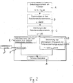
- the Fig. 3 shows that for detecting the loading moments of the robot rocker in a movement thereof (and the following robot elements) about the vertical axis A1, a strain gauge 8 on one side (the right or left side of the robot rocker 5 is arranged.
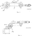
- the shows Fig. 4 to arrange for the detection of the reaction or loading moments of a movement about the first horizontal axis A2 a corresponding strain gauge 8 on the top (or on the underside) of the rocker 5.
- the Fig. 5 to 7 show concrete embodiments of the method according to the invention and a robot according to the invention with moving parts as well as the monitoring of the machine or the robot 1 by means of detection of the physical parameter material tension. Furthermore, in the Fig. 5 schematically a person 9 shown.
- a robot arm 6 hits from above, as in FIG Fig. 5 shown, on the shoulder of a person or he strikes from above on another object, so there are increased bending moments in the robot arm 6 and thus material stresses in this, by means of measuring strips 8 on the robot arm 6, in particular by on the bottom and on the top the arm arranged measuring strip 8 can be measured.
- suitable transducers such as in particular strain gauges or photoconductor-based transducers.
- the sensors detecting the resulting material stresses provide a constant image of the structural load during operation of the robot.
- the measured values obtained can be further processed and used in a number of ways, in particular online for monitoring and backup purposes, in order to permanently compare the measured values with predetermined reference values or limit values in order to ensure safety of the human-machine system by movements, namely speeds Accelerations, are kept within a tolerable range and / or abutment of a robot part against a man a stopped success.
- a reference curve R for a given movement of the robot or a robot part.
- the reference curve R is assigned a tolerable range as the reference corridor S.
- the shows Fig. 4 a trace M, which shows the actual location of the robot part in an operation over time.
- the measurement curve M moves out of the reference corridor S and thus indicates an impermissible movement or collision with unexpected measurement values. This can be effected, for example, a shutdown of the robot.
Landscapes
- Engineering & Computer Science (AREA)
- Robotics (AREA)
- Mechanical Engineering (AREA)
- Manipulator (AREA)
- Numerical Control (AREA)
Claims (20)
- Procédé de surveillance de parties mobiles d'un robot industriel (1), dans lequel des valeurs de mesure de deux grandeurs de mesure différentes sont détectés et au moins une de ces valeurs de mesure est traitée pour obtenir un premier résultat de mesure, caractérisé en ce que la valeur de mesure est traitée de telle sorte pour obtenir un premier résultat de mesure que celui-ci peut être comparé à la valeur de mesure de l'autre grandeur de mesure ou avec un deuxième résultat de mesure obtenu sur la base de cette valeur de mesure, en ce que le premier résultat de mesure est comparé avec la valeur de mesure de l'autre grandeur de mesure ou avec le deuxième résultat de mesure obtenu sur la base de cette valeur de mesure et en ce qu'un signal caractérisant le résultat de la comparaison est fourni.
- Procédé selon la revendication 1, caractérisé en ce que, en tant qu'au moins une grandeur de valeur, des tensions de matériau sont mesurées sur des pièces de la machine.
- Procédé selon la revendication 2, caractérisé en ce que les tensions de matériau sont mesurées au moyen d'au moins un capteur de valeurs de mesure (8).
- Procédé selon la revendication 2 ou 3, caractérisé en ce que les tensions de matériau sont mesurées au moyen d'une jauge d'extensométrie (8).
- Procédé selon l'une des revendications 2 ou 3, caractérisé en ce que les tensions de matériau sont mesurées au moyen d'un capteur piézoélectrique ou basé sur un guide de lumière.
- Procédé selon l'une des revendications 2 à 5, caractérisé en ce que les tensions de matériau sont mesurées au moyen de capteurs de valeurs de mesure (8) agencés sur au moins deux surfaces d'une pièce de robot.
- Procédé selon l'une des revendications précédentes, caractérisé en ce que des valeurs de mesure actuelles de grandeurs de mesure ou de résultats de mesure, respectivement, sont comparées à des valeurs de référence.
- Procédé selon la revendication 7, caractérisé en ce que des valeurs de mesure actuelles de grandeurs de mesure et/ou des résultats de mesure actuels, respectivement, sont comparés à des valeurs de référence, compte tenu de tolérances.
- Procédé selon la revendication 8, caractérisé en ce que des tolérances sont prises en compte par la formation d'un corridor de référence vers une courbe de référence.
- Procédé selon l'une des revendications précédentes, caractérisé en ce qu'en cas de déviations de valeurs de mesures attendues et/ou de résultats de mesure attendus, un arrêt du robot a lieu.
- Robot industriel (1) présentant deux dispositifs de mesure pour détecter des grandeurs de mesure différentes en tant que valeurs de mesure sur des parties mobiles du robot industriel, caractérisé par au moins une unité de traitement (12, 13, 14) pour au moins une des valeurs de mesure des grandeurs de mesure pour le traitement de cette valeur de mesure dans un premier résultat de mesure comparable à l'autre valeur de mesure de l'autre grande de mesure ou dans un deuxième résultat de mesure obtenu à partir de cette valeur de mesure et par une unité de comparaison (15) pour comparer le premier résultat de mesure à la valeur de mesure de l'autre grandeur de mesure ou à un deuxième résultat de mesure obtenu sur la base de cette valeur de mesure.
- Robot industriel selon la revendication 11, caractérisé par des dispositifs de mesure pour déterminer des tensions de matériau.
- Robot industriel selon la revendication 12, caractérisé en ce que les dispositifs pour déterminer des tensions de matériau sont réalisés sous forme de capteurs de valeurs de mesure.
- Robot industriel selon la revendication 12 ou 13, caractérisé en ce que les dispositifs pour déterminer des tensions de matériau sont réalisés sous forme de jauges d'extensométrie (8).
- Robot industriel selon l'une des revendications 12 à 14, caractérisé en ce que les dispositifs pour déterminer des tensions de matériau sont réalisés sous forme de capteurs basés sur un guide lumière.
- Robot industriel selon l'une des revendications 12 à 15, caractérisé en ce qu'au moins un dispositif pour déterminer des tensions de matériau est agencé sur chacune d'au moins deux surfaces d'une pièce de robot.
- Robot industriel selon l'une des revendications 12 à 16, caractérisé par un dispositif de surveillance (11) auquel est relié au moins un dispositif pour déterminer des tensions de matériau sur des pièces de machine du robot industriel.
- Robot selon la revendication 16 ou 17, caractérisé en ce que le dispositif de surveillance (11) présente des unités pour la surveillance au moins d'allongements des structures de machine du robot industriel ainsi que d'une autre grandeur de mesure.
- Robot industriel selon l'une des revendications 16 à 18, caractérisé en ce que le dispositif de surveillance (11) présente un dispositif de comparaison (15) pour comparer des valeurs de mesure actuelles et/ou des résultats actuels avec des modèles prédéterminés pour des mouvements de robot (16).
- Robot industriel selon l'une des revendications 18 à 19, caractérisé en ce que le dispositif de surveillance (11) présente un dispositif de commutation (17) pour arrêter le robot industriel.
Applications Claiming Priority (2)
| Application Number | Priority Date | Filing Date | Title |
|---|---|---|---|
| DE10304019 | 2003-02-01 | ||
| DE10304019A DE10304019A1 (de) | 2003-02-01 | 2003-02-01 | Verfahren zum Überwachen einer Maschine und derartige Maschine, insbesondere Roboter |
Publications (4)
| Publication Number | Publication Date |
|---|---|
| EP1445075A2 EP1445075A2 (fr) | 2004-08-11 |
| EP1445075A3 EP1445075A3 (fr) | 2008-04-09 |
| EP1445075B1 true EP1445075B1 (fr) | 2017-04-12 |
| EP1445075B2 EP1445075B2 (fr) | 2022-01-12 |
Family
ID=32603084
Family Applications (1)
| Application Number | Title | Priority Date | Filing Date |
|---|---|---|---|
| EP04001285.8A Expired - Lifetime EP1445075B2 (fr) | 2003-02-01 | 2004-01-22 | méthode pour surveiller un robot et robot munie de moyens de surveillance |
Country Status (4)
| Country | Link |
|---|---|
| US (1) | US7086293B2 (fr) |
| EP (1) | EP1445075B2 (fr) |
| DE (1) | DE10304019A1 (fr) |
| DK (1) | DK1445075T3 (fr) |
Cited By (1)
| Publication number | Priority date | Publication date | Assignee | Title |
|---|---|---|---|---|
| WO2022120820A1 (fr) * | 2020-12-11 | 2022-06-16 | Abb Schweiz Ag | Système de commande de robot, procédé de commande de robot et robot |
Families Citing this family (40)
| Publication number | Priority date | Publication date | Assignee | Title |
|---|---|---|---|---|
| US7391178B2 (en) * | 2002-07-18 | 2008-06-24 | Kabushiki Kaisha Yaskawa Denki | Robot controller and robot system |
| DE10304019A1 (de) * | 2003-02-01 | 2004-11-04 | Kuka Roboter Gmbh | Verfahren zum Überwachen einer Maschine und derartige Maschine, insbesondere Roboter |
| AT502286B1 (de) * | 2004-09-15 | 2008-09-15 | Wfl Millturn Tech Gmbh & Co Kg | Verfahren zur kollisionsvermeidung |
| EP1764192B1 (fr) * | 2005-09-16 | 2009-11-25 | Abb Ab | Robot industriel avec capteurs dans la zone d'une bride pour outils |
| EP1854425A1 (fr) | 2006-05-11 | 2007-11-14 | BrainLAB AG | Localisation spatiale pour appareils médicaux avec mesure de localisation redondante et pondération pour prioriser les mesures |
| DE602006007823D1 (de) * | 2006-05-16 | 2009-08-27 | Abb Ab | Steuersystem für einen Industrieroboter |
| DE102006055849A1 (de) * | 2006-11-27 | 2008-05-29 | Innotec Gmbh | Verfahren zur sicherheitsgerichteten Abschaltung von Bewegungsvorgängen im Kollisionsfall |
| EP1932629B1 (fr) * | 2006-12-11 | 2019-04-24 | ABB Research Ltd. | Procédé et système de commande pour surveiller l'état d'un robot industriel |
| EP1955830B1 (fr) | 2007-02-06 | 2014-04-09 | Abb Research Ltd. | Procédé et système de commande pour surveiller l' état d' un robot industriel |
| DE102007006708A1 (de) | 2007-02-10 | 2008-08-14 | Abb Research Ltd. | Verfahren zur Sicherung eines Handhabungsgeräts |
| DE102007050232B4 (de) * | 2007-10-20 | 2024-05-02 | Deutsches Zentrum für Luft- und Raumfahrt e.V. | Handhabungsroboter und Verfahren zur Steuerung eines Handhabungsroboters |
| DE102007060682B4 (de) * | 2007-12-17 | 2015-08-20 | Kuka Roboter Gmbh | Verfahren und Vorrichtung zur modellbasierten Regelung eines Manipulators |
| DE102007063099A1 (de) * | 2007-12-28 | 2009-07-02 | Kuka Roboter Gmbh | Roboter und Verfahren zum Überwachen der Momente an einem solchen |
| JP2009297810A (ja) * | 2008-06-11 | 2009-12-24 | Panasonic Corp | マニピュレータの姿勢制御装置および姿勢制御方法 |
| DE102008054312A1 (de) | 2008-11-03 | 2010-05-06 | Kuka Roboter Gmbh | Verfahren und Vorrichtung zur sicheren Erfassung einer kinematischen Größe eines Manipulators |
| DE102010029186A1 (de) | 2010-05-20 | 2011-11-24 | Kuka Roboter Gmbh | Messvorrichtung und Roboter |
| DE102010033248A1 (de) | 2010-08-03 | 2012-01-19 | Kuka Laboratories Gmbh | Verfahren und Vorrichtung zur Überwachung eines Manipulators |
| US8781629B2 (en) | 2010-09-22 | 2014-07-15 | Toyota Motor Engineering & Manufacturing North America, Inc. | Human-robot interface apparatuses and methods of controlling robots |
| DE102011106321A1 (de) * | 2011-07-01 | 2013-01-03 | Kuka Laboratories Gmbh | Verfahren und Steuermittel zum Steuern eines Roboters |
| JP5912683B2 (ja) * | 2012-03-07 | 2016-04-27 | 株式会社神戸製鋼所 | モータ駆動構造を備えたシステム、モータ駆動構造のシステムに用いられるプログラム、および溶接物製造方法 |
| WO2014071575A1 (fr) * | 2012-11-07 | 2014-05-15 | Abb Technology Ltd | Unité de dispositif de redondance et procédé pour déterminer un défaut dans un système de commande industriel, système de commande industriel et système industriel comprenant l'unité de dispositif de redondance |
| DE102013010290A1 (de) | 2013-06-19 | 2014-12-24 | Kuka Laboratories Gmbh | Überwachen eines kinematisch redundanten Roboters |
| US9884426B2 (en) | 2013-06-27 | 2018-02-06 | De-Sta-Co Europe Gmbh | Boom utilized in a geometric end effector system |
| US9446517B2 (en) * | 2013-10-17 | 2016-09-20 | Intuitive Surgical Operations, Inc. | Fault reaction, fault isolation, and graceful degradation in a robotic system |
| DE202013105036U1 (de) * | 2013-11-08 | 2015-02-10 | Daimler Ag | Erfassungseinrichtung |
| KR101526424B1 (ko) * | 2013-12-18 | 2015-06-05 | 현대자동차 주식회사 | 차량용 헤드 업 디스플레이 검사장치 및 그 방법 |
| JP2016064479A (ja) * | 2014-09-25 | 2016-04-28 | ファナック株式会社 | ロボット制御装置 |
| DE102015211348A1 (de) * | 2015-06-19 | 2016-12-22 | Krones Aktiengesellschaft | Handhabungsvorrichtung und Verfahren zur Handhabung von Artikeln |
| EP3020514B1 (fr) * | 2014-11-17 | 2023-10-11 | KRONES Aktiengesellschaft | Dispositif de manipulation et procédé de manipulation d'articles |
| DE102014223419A1 (de) * | 2014-11-17 | 2016-05-19 | Krones Aktiengesellschaft | Verfahren und Vorrichtung zur Handhabung und/oder zum Manipulieren von Artikeln wie Gebinden oder Stückgütern |
| DE102015212171B3 (de) | 2015-06-30 | 2016-06-30 | Kuka Roboter Gmbh | Verfahren zum Steuern eines Manipulatorsystems |
| CN108027298A (zh) * | 2015-10-28 | 2018-05-11 | 西门子公司 | 一种用于异常检测的方法和装置 |
| EP3554774B1 (fr) | 2016-12-16 | 2025-07-16 | MAKO Surgical Corp. | Techniques de détection d'erreurs ou de perte de précision dans un système chirurgical robotisé |
| DE102016015237B4 (de) * | 2016-12-21 | 2019-02-21 | Kuka Roboter Gmbh | Sichere Ermittlung von Achsstellungen und/oder -geschwindigkeiten eines Roboters |
| WO2018133964A1 (fr) | 2017-01-18 | 2018-07-26 | Siemens Wind Power A/S | Agencement de plateforme standardisée d'une éolienne |
| DE102018204184A1 (de) * | 2018-03-19 | 2019-09-19 | Leoni Kabel Gmbh | Verfahren zur Überwachung eines Versorgungssystems eines Roboters |
| US11386289B2 (en) * | 2019-11-05 | 2022-07-12 | Elementary Robotics, Inc. | Systems and methods for robot-aided product inspection |
| CN113043269B (zh) * | 2019-12-27 | 2024-04-05 | 深圳慧智星晨科技有限公司 | 一种基于机器人模型的机器人接触力观测系统 |
| WO2021259459A1 (fr) * | 2020-06-24 | 2021-12-30 | Abb Schweiz Ag | Système de test de rembourrage d'un manipulateur robotique |
| DE102023211163A1 (de) | 2023-11-10 | 2025-05-15 | Bizlink Industry Germany Gmbh | Gelenkarmroboter sowie Verfahren zum Überwachen eines Gelenkarmroboters |
Family Cites Families (18)
| Publication number | Priority date | Publication date | Assignee | Title |
|---|---|---|---|---|
| DE3244738A1 (de) * | 1982-12-03 | 1984-06-07 | Uraca Pumpenfabrik GmbH & Co KG, 7432 Urach | Vorrichtung zur ueberwachung von ventilen einer intermittierend arbeitenden maschine |
| JPS59108691A (ja) * | 1982-12-13 | 1984-06-23 | 株式会社日立製作所 | バランサ制御方式 |
| DE3407618A1 (de) * | 1984-03-01 | 1985-09-12 | Klaus Prof. Dr.-Ing. 4006 Erkrath Brankamp | Vorrichtung zur erfassung einer zwischen zwei gegeneinander bewegbaren maschinenteilen auftretenden kraft |
| CA1233222A (fr) * | 1984-03-09 | 1988-02-23 | Nobuhiko Onda | Systeme de manoeuvre pour dispositif mobile |
| JPS61226287A (ja) * | 1985-03-07 | 1986-10-08 | エプシロン テクノロジー インコーポレーテツド | 加工品を取扱うたぬの装置および方法 |
| US4783107A (en) * | 1985-06-04 | 1988-11-08 | Clemson University | Method and apparatus for controlling impact force during rapid robotic acquisition of object |
| US4715773A (en) * | 1985-06-04 | 1987-12-29 | Clemson University | Method and apparatus for repositioning a mislocated object with a robot hand |
| FR2589238B1 (fr) * | 1985-10-25 | 1987-11-20 | Commissariat Energie Atomique | Capteur de mesure d'efforts et de couples et applications d'un tel capteur a un palpeur et a un dispositif de prehension |
| DE3624941C2 (de) * | 1986-07-23 | 1995-01-19 | Loedige Maschbau Gmbh Geb | Verfahren zum Überwachen von Betriebsbedingungen kontinuierlich arbeitender Maschinen und danach arbeitender Mischer |
| US5081593A (en) * | 1989-08-16 | 1992-01-14 | Megamation Incorporated | Method and apparatus for monitoring and controlling linear motor robot apparatus and the like |
| JPH03178788A (ja) * | 1989-12-06 | 1991-08-02 | Hitachi Ltd | マニピュレータの制御方法 |
| JPH05269684A (ja) * | 1992-03-23 | 1993-10-19 | Mitsubishi Electric Corp | 産業ロボット装置 |
| US5440935A (en) * | 1993-03-18 | 1995-08-15 | Mts Systems Corporation | Apparatus for combining transducer output signals |
| DE4432759A1 (de) * | 1994-09-14 | 1996-03-21 | Gemac Ges Fuer Mikroelektronik | Variabler Sicherheitsmodul zur Überwachung und Steuerung sicherheitsrelevanter Maschinenparamter und Betriebszustände |
| JPH08118284A (ja) * | 1994-10-26 | 1996-05-14 | Toshiba Corp | 産業用ロボット |
| JPH1158278A (ja) * | 1997-08-25 | 1999-03-02 | Yaskawa Electric Corp | ロボットの制御装置 |
| DE10020174A1 (de) * | 2000-04-25 | 2001-11-15 | Bosch Gmbh Robert | Automatische Überwachungsanordnung von Wälzlagern in Maschinen und Werkzeugen |
| DE10304019A1 (de) * | 2003-02-01 | 2004-11-04 | Kuka Roboter Gmbh | Verfahren zum Überwachen einer Maschine und derartige Maschine, insbesondere Roboter |
-
2003
- 2003-02-01 DE DE10304019A patent/DE10304019A1/de not_active Ceased
-
2004
- 2004-01-22 DK DK04001285.8T patent/DK1445075T3/en active
- 2004-01-22 EP EP04001285.8A patent/EP1445075B2/fr not_active Expired - Lifetime
- 2004-01-28 US US10/766,769 patent/US7086293B2/en not_active Expired - Lifetime
Non-Patent Citations (4)
| Title |
|---|
| D.G. LUENBERGER: "Observing the state of a linear system", IEEE TRANSACTION ON MILITARY ELECTRONICS, vol. 8, 1964, pages 74 - 80, XP055453534 |
| H.-B. KUNTZE ET AL.: "On A SMART STRUCTURE VARIABLE SUPERVISORY CONTROL CONCEPT FOR HUMANOID ROBOTS", INT. CONF. ON HUMANOID ROBOTS KARLSRUHE, CONFERENCE DOCUMENTATION, January 2003 (2003-01-01), XP055453528 |
| K. SUITA ET AL.: "A failure-to-safety ''Kyozon'' system with simple contact detection and stop capabilities for safe human -autonomous robot coexistence", PROC. IEEE INT. CONF. ON ROBOTICS AND AUTOMATION, 1995, pages 3089 - 3096, XP000731687 |
| M. L. VISINSKY ET AL.: "Robotic fault detection and fault tolerance: A survey", RELIABILTY ENGINEERING AND SYSTEM SAFETY, vol. 46, 1994, pages 139 - 158, XP055108909 |
Cited By (1)
| Publication number | Priority date | Publication date | Assignee | Title |
|---|---|---|---|---|
| WO2022120820A1 (fr) * | 2020-12-11 | 2022-06-16 | Abb Schweiz Ag | Système de commande de robot, procédé de commande de robot et robot |
Also Published As
| Publication number | Publication date |
|---|---|
| US7086293B2 (en) | 2006-08-08 |
| DE10304019A1 (de) | 2004-11-04 |
| EP1445075B2 (fr) | 2022-01-12 |
| US20040260481A1 (en) | 2004-12-23 |
| DK1445075T3 (en) | 2017-07-24 |
| EP1445075A3 (fr) | 2008-04-09 |
| EP1445075A2 (fr) | 2004-08-11 |
Similar Documents
| Publication | Publication Date | Title |
|---|---|---|
| EP1445075B1 (fr) | méthode pour surveiller un robot et robot muni de moyens de surveillance | |
| EP2347309B1 (fr) | Procédé et dispositif pour la détection fiable d'une grandeur cinématique d'un manipulateur | |
| DE2628701C2 (fr) | ||
| EP2807103B1 (fr) | Dispositif de sécurité et procédé de contrôle d'une installation d'ascenseur | |
| EP0391174B2 (fr) | Dispositif et méthode pour détecter des paramètres physiques d'un élévateur | |
| DE102010044644B4 (de) | Verfahren zur Kollisionserkennung für eine Antriebseinheit | |
| EP2628575B1 (fr) | Procédé destiné à déterminer un couple et robot industriel | |
| EP1600833A2 (fr) | Procédé et dispositif de fonctionnement d' une machine, comme un robot industriel multi-axes | |
| DE102015224641A1 (de) | Verfahren zum Erkennen einer Kollision eines Roboterarms mit einem Objekt und Roboter mit einem Roboterarm | |
| DE3911391A1 (de) | Verfahren zum erfassen von physikalischen kenngroessen eines aufzugs | |
| EP2388565B1 (fr) | Dispositif de mesure et robot | |
| DE102018104082B4 (de) | Robotersystem | |
| DE102017115800B4 (de) | Anordnung für einen Knickarmroboter und Verfahren zum Bestimmen einer Positionierung einer Aufnahme für einen Endeffektor eines Knickarmroboters | |
| EP4124789B1 (fr) | Fixation d'une pièce de machine mobile | |
| EP3439834B1 (fr) | Commande cartésienne d'une pointe de mât d'un manipulateur de grande dimension, en particulier une pompe à béton | |
| EP0985989B1 (fr) | Méthode et dispositif pour améliorer le comportement dynamique d'un robot | |
| EP3298377B1 (fr) | Dispositif de pendule de test et procédé de fonctionnement d'un dispositif de pendule de test | |
| DE102020126209A1 (de) | Roboter | |
| DE112020003134T5 (de) | Vorrichtung und verfahren zur fehlerdiagnose eines drehzahlminderers | |
| EP3839153A1 (fr) | Procédé d'étalonnage d'un capteur de position | |
| DE102019129721B3 (de) | Bremsvorrichtungssystem, Prüfpendelanordnung zur Durchführung von Halszertifizierungen sowie Verfahren zum Betrieb einer Prüfpendelanordnung | |
| DE102019204564B4 (de) | Ermitteln eines Parameters einer auf einen Roboter wirkenden Kraft | |
| DE102019114463B4 (de) | Überlast- und Bruch-Überwachungsverfahren und -system für ein Hochauftriebssystem eines Flugzeugs | |
| DE102020203671B4 (de) | Verfahren zum Steuern eines Roboterarms | |
| DE102023132884B4 (de) | Verfahren zum Überwachen eines fahrerlosen Transportfahrzeugs |
Legal Events
| Date | Code | Title | Description |
|---|---|---|---|
| PUAI | Public reference made under article 153(3) epc to a published international application that has entered the european phase |
Free format text: ORIGINAL CODE: 0009012 |
|
| AK | Designated contracting states |
Kind code of ref document: A2 Designated state(s): AT BE BG CH CY CZ DE DK EE ES FI FR GB GR HU IE IT LI LU MC NL PT RO SE SI SK TR |
|
| AX | Request for extension of the european patent |
Extension state: AL LT LV MK |
|
| PUAL | Search report despatched |
Free format text: ORIGINAL CODE: 0009013 |
|
| AK | Designated contracting states |
Kind code of ref document: A3 Designated state(s): AT BE BG CH CY CZ DE DK EE ES FI FR GB GR HU IE IT LI LU MC NL PT RO SE SI SK TR |
|
| AX | Request for extension of the european patent |
Extension state: AL LT LV MK |
|
| 17P | Request for examination filed |
Effective date: 20080905 |
|
| AKX | Designation fees paid |
Designated state(s): AT BE BG CH CY CZ DE DK EE ES FI FR GB GR HU IE IT LI LU MC NL PT RO SE SI SK TR |
|
| 17Q | First examination report despatched |
Effective date: 20110609 |
|
| GRAP | Despatch of communication of intention to grant a patent |
Free format text: ORIGINAL CODE: EPIDOSNIGR1 |
|
| STAA | Information on the status of an ep patent application or granted ep patent |
Free format text: STATUS: GRANT OF PATENT IS INTENDED |
|
| INTG | Intention to grant announced |
Effective date: 20170109 |
|
| GRAS | Grant fee paid |
Free format text: ORIGINAL CODE: EPIDOSNIGR3 |
|
| GRAA | (expected) grant |
Free format text: ORIGINAL CODE: 0009210 |
|
| STAA | Information on the status of an ep patent application or granted ep patent |
Free format text: STATUS: THE PATENT HAS BEEN GRANTED |
|
| AK | Designated contracting states |
Kind code of ref document: B1 Designated state(s): AT BE BG CH CY CZ DE DK EE ES FI FR GB GR HU IE IT LI LU MC NL PT RO SE SI SK TR |
|
| REG | Reference to a national code |
Ref country code: GB Ref legal event code: FG4D Free format text: NOT ENGLISH |
|
| REG | Reference to a national code |
Ref country code: CH Ref legal event code: EP |
|
| REG | Reference to a national code |
Ref country code: IE Ref legal event code: FG4D Free format text: LANGUAGE OF EP DOCUMENT: GERMAN |
|
| REG | Reference to a national code |
Ref country code: AT Ref legal event code: REF Ref document number: 883388 Country of ref document: AT Kind code of ref document: T Effective date: 20170515 |
|
| REG | Reference to a national code |
Ref country code: DE Ref legal event code: R096 Ref document number: 502004015500 Country of ref document: DE |
|
| REG | Reference to a national code |
Ref country code: CH Ref legal event code: NV Representative=s name: FIAMMENGHI-FIAMMENGHI, CH Ref country code: CH Ref legal event code: PCOW Free format text: NEW ADDRESS: ZUGSPITZSTRASSE 140, 86165 AUGSBURG (DE) |
|
| REG | Reference to a national code |
Ref country code: SE Ref legal event code: TRGR |
|
| REG | Reference to a national code |
Ref country code: DK Ref legal event code: T3 Effective date: 20170719 |
|
| REG | Reference to a national code |
Ref country code: NL Ref legal event code: MP Effective date: 20170412 |
|
| PG25 | Lapsed in a contracting state [announced via postgrant information from national office to epo] |
Ref country code: NL Free format text: LAPSE BECAUSE OF FAILURE TO SUBMIT A TRANSLATION OF THE DESCRIPTION OR TO PAY THE FEE WITHIN THE PRESCRIBED TIME-LIMIT Effective date: 20170412 |
|
| PG25 | Lapsed in a contracting state [announced via postgrant information from national office to epo] |
Ref country code: FI Free format text: LAPSE BECAUSE OF FAILURE TO SUBMIT A TRANSLATION OF THE DESCRIPTION OR TO PAY THE FEE WITHIN THE PRESCRIBED TIME-LIMIT Effective date: 20170412 Ref country code: GR Free format text: LAPSE BECAUSE OF FAILURE TO SUBMIT A TRANSLATION OF THE DESCRIPTION OR TO PAY THE FEE WITHIN THE PRESCRIBED TIME-LIMIT Effective date: 20170713 Ref country code: ES Free format text: LAPSE BECAUSE OF FAILURE TO SUBMIT A TRANSLATION OF THE DESCRIPTION OR TO PAY THE FEE WITHIN THE PRESCRIBED TIME-LIMIT Effective date: 20170412 |
|
| PG25 | Lapsed in a contracting state [announced via postgrant information from national office to epo] |
Ref country code: BG Free format text: LAPSE BECAUSE OF FAILURE TO SUBMIT A TRANSLATION OF THE DESCRIPTION OR TO PAY THE FEE WITHIN THE PRESCRIBED TIME-LIMIT Effective date: 20170712 |
|
| REG | Reference to a national code |
Ref country code: FR Ref legal event code: PLFP Year of fee payment: 15 |
|
| REG | Reference to a national code |
Ref country code: DE Ref legal event code: R026 Ref document number: 502004015500 Country of ref document: DE |
|
| PLBI | Opposition filed |
Free format text: ORIGINAL CODE: 0009260 |
|
| PLAX | Notice of opposition and request to file observation + time limit sent |
Free format text: ORIGINAL CODE: EPIDOSNOBS2 |
|
| PG25 | Lapsed in a contracting state [announced via postgrant information from national office to epo] |
Ref country code: RO Free format text: LAPSE BECAUSE OF FAILURE TO SUBMIT A TRANSLATION OF THE DESCRIPTION OR TO PAY THE FEE WITHIN THE PRESCRIBED TIME-LIMIT Effective date: 20170412 Ref country code: EE Free format text: LAPSE BECAUSE OF FAILURE TO SUBMIT A TRANSLATION OF THE DESCRIPTION OR TO PAY THE FEE WITHIN THE PRESCRIBED TIME-LIMIT Effective date: 20170412 Ref country code: SK Free format text: LAPSE BECAUSE OF FAILURE TO SUBMIT A TRANSLATION OF THE DESCRIPTION OR TO PAY THE FEE WITHIN THE PRESCRIBED TIME-LIMIT Effective date: 20170412 Ref country code: CZ Free format text: LAPSE BECAUSE OF FAILURE TO SUBMIT A TRANSLATION OF THE DESCRIPTION OR TO PAY THE FEE WITHIN THE PRESCRIBED TIME-LIMIT Effective date: 20170412 |
|
| 26 | Opposition filed |
Opponent name: FRANKA EMIKA GMBH Effective date: 20180112 |
|
| PLBB | Reply of patent proprietor to notice(s) of opposition received |
Free format text: ORIGINAL CODE: EPIDOSNOBS3 |
|
| PG25 | Lapsed in a contracting state [announced via postgrant information from national office to epo] |
Ref country code: SI Free format text: LAPSE BECAUSE OF FAILURE TO SUBMIT A TRANSLATION OF THE DESCRIPTION OR TO PAY THE FEE WITHIN THE PRESCRIBED TIME-LIMIT Effective date: 20170412 |
|
| RAP2 | Party data changed (patent owner data changed or rights of a patent transferred) |
Owner name: KUKA DEUTSCHLAND GMBH |
|
| PG25 | Lapsed in a contracting state [announced via postgrant information from national office to epo] |
Ref country code: LU Free format text: LAPSE BECAUSE OF NON-PAYMENT OF DUE FEES Effective date: 20180122 |
|
| REG | Reference to a national code |
Ref country code: IE Ref legal event code: MM4A |
|
| REG | Reference to a national code |
Ref country code: BE Ref legal event code: MM Effective date: 20180131 |
|
| PG25 | Lapsed in a contracting state [announced via postgrant information from national office to epo] |
Ref country code: BE Free format text: LAPSE BECAUSE OF NON-PAYMENT OF DUE FEES Effective date: 20180131 |
|
| PG25 | Lapsed in a contracting state [announced via postgrant information from national office to epo] |
Ref country code: IE Free format text: LAPSE BECAUSE OF NON-PAYMENT OF DUE FEES Effective date: 20180122 |
|
| REG | Reference to a national code |
Ref country code: AT Ref legal event code: MM01 Ref document number: 883388 Country of ref document: AT Kind code of ref document: T Effective date: 20180122 |
|
| PG25 | Lapsed in a contracting state [announced via postgrant information from national office to epo] |
Ref country code: AT Free format text: LAPSE BECAUSE OF NON-PAYMENT OF DUE FEES Effective date: 20180122 |
|
| PG25 | Lapsed in a contracting state [announced via postgrant information from national office to epo] |
Ref country code: MC Free format text: LAPSE BECAUSE OF FAILURE TO SUBMIT A TRANSLATION OF THE DESCRIPTION OR TO PAY THE FEE WITHIN THE PRESCRIBED TIME-LIMIT Effective date: 20170412 |
|
| APBM | Appeal reference recorded |
Free format text: ORIGINAL CODE: EPIDOSNREFNO |
|
| APBP | Date of receipt of notice of appeal recorded |
Free format text: ORIGINAL CODE: EPIDOSNNOA2O |
|
| APAH | Appeal reference modified |
Free format text: ORIGINAL CODE: EPIDOSCREFNO |
|
| APAW | Appeal reference deleted |
Free format text: ORIGINAL CODE: EPIDOSDREFNO |
|
| APBQ | Date of receipt of statement of grounds of appeal recorded |
Free format text: ORIGINAL CODE: EPIDOSNNOA3O |
|
| APBQ | Date of receipt of statement of grounds of appeal recorded |
Free format text: ORIGINAL CODE: EPIDOSNNOA3O |
|
| PG25 | Lapsed in a contracting state [announced via postgrant information from national office to epo] |
Ref country code: TR Free format text: LAPSE BECAUSE OF FAILURE TO SUBMIT A TRANSLATION OF THE DESCRIPTION OR TO PAY THE FEE WITHIN THE PRESCRIBED TIME-LIMIT Effective date: 20170412 |
|
| PG25 | Lapsed in a contracting state [announced via postgrant information from national office to epo] |
Ref country code: PT Free format text: LAPSE BECAUSE OF FAILURE TO SUBMIT A TRANSLATION OF THE DESCRIPTION OR TO PAY THE FEE WITHIN THE PRESCRIBED TIME-LIMIT Effective date: 20170412 Ref country code: HU Free format text: LAPSE BECAUSE OF FAILURE TO SUBMIT A TRANSLATION OF THE DESCRIPTION OR TO PAY THE FEE WITHIN THE PRESCRIBED TIME-LIMIT; INVALID AB INITIO Effective date: 20040122 |
|
| PG25 | Lapsed in a contracting state [announced via postgrant information from national office to epo] |
Ref country code: CY Free format text: LAPSE BECAUSE OF FAILURE TO SUBMIT A TRANSLATION OF THE DESCRIPTION OR TO PAY THE FEE WITHIN THE PRESCRIBED TIME-LIMIT Effective date: 20170412 |
|
| REG | Reference to a national code |
Ref country code: DE Ref legal event code: R082 Ref document number: 502004015500 Country of ref document: DE Representative=s name: KILBURN & STRODE LLP, NL |
|
| APBU | Appeal procedure closed |
Free format text: ORIGINAL CODE: EPIDOSNNOA9O |
|
| PUAH | Patent maintained in amended form |
Free format text: ORIGINAL CODE: 0009272 |
|
| STAA | Information on the status of an ep patent application or granted ep patent |
Free format text: STATUS: PATENT MAINTAINED AS AMENDED |
|
| 27A | Patent maintained in amended form |
Effective date: 20220112 |
|
| AK | Designated contracting states |
Kind code of ref document: B2 Designated state(s): AT BE BG CH CY CZ DE DK EE ES FI FR GB GR HU IE IT LI LU MC NL PT RO SE SI SK TR |
|
| REG | Reference to a national code |
Ref country code: DE Ref legal event code: R102 Ref document number: 502004015500 Country of ref document: DE |
|
| PGFP | Annual fee paid to national office [announced via postgrant information from national office to epo] |
Ref country code: SE Payment date: 20211210 Year of fee payment: 19 |
|
| PGFP | Annual fee paid to national office [announced via postgrant information from national office to epo] |
Ref country code: DK Payment date: 20220110 Year of fee payment: 19 |
|
| REG | Reference to a national code |
Ref country code: SE Ref legal event code: NAV |
|
| PGFP | Annual fee paid to national office [announced via postgrant information from national office to epo] |
Ref country code: IT Payment date: 20211213 Year of fee payment: 19 |
|
| PG25 | Lapsed in a contracting state [announced via postgrant information from national office to epo] |
Ref country code: DK Free format text: LAPSE BECAUSE OF FAILURE TO SUBMIT A TRANSLATION OF THE DESCRIPTION OR TO PAY THE FEE WITHIN THE PRESCRIBED TIME-LIMIT Effective date: 20220112 |
|
| PGFP | Annual fee paid to national office [announced via postgrant information from national office to epo] |
Ref country code: GB Payment date: 20221201 Year of fee payment: 20 Ref country code: FR Payment date: 20221208 Year of fee payment: 20 |
|
| PGFP | Annual fee paid to national office [announced via postgrant information from national office to epo] |
Ref country code: CH Payment date: 20230106 Year of fee payment: 20 |
|
| PGFP | Annual fee paid to national office [announced via postgrant information from national office to epo] |
Ref country code: DE Payment date: 20221130 Year of fee payment: 20 |
|
| P01 | Opt-out of the competence of the unified patent court (upc) registered |
Effective date: 20230528 |
|
| REG | Reference to a national code |
Ref country code: DE Ref legal event code: R071 Ref document number: 502004015500 Country of ref document: DE |
|
| PG25 | Lapsed in a contracting state [announced via postgrant information from national office to epo] |
Ref country code: IT Free format text: LAPSE BECAUSE OF NON-PAYMENT OF DUE FEES Effective date: 20230122 |
|
| REG | Reference to a national code |
Ref country code: CH Ref legal event code: PL |
|
| REG | Reference to a national code |
Ref country code: GB Ref legal event code: PE20 Expiry date: 20240121 |
|
| PG25 | Lapsed in a contracting state [announced via postgrant information from national office to epo] |
Ref country code: GB Free format text: LAPSE BECAUSE OF EXPIRATION OF PROTECTION Effective date: 20240121 |
|
| PG25 | Lapsed in a contracting state [announced via postgrant information from national office to epo] |
Ref country code: SE Free format text: LAPSE BECAUSE OF NON-PAYMENT OF DUE FEES Effective date: 20230123 |