EP1445125A2 - Reifenzustands- Überwachungsgerät - Google Patents
Reifenzustands- Überwachungsgerät Download PDFInfo
- Publication number
- EP1445125A2 EP1445125A2 EP03021753A EP03021753A EP1445125A2 EP 1445125 A2 EP1445125 A2 EP 1445125A2 EP 03021753 A EP03021753 A EP 03021753A EP 03021753 A EP03021753 A EP 03021753A EP 1445125 A2 EP1445125 A2 EP 1445125A2
- Authority
- EP
- European Patent Office
- Prior art keywords
- tire
- data
- transmitters
- receiver
- tires
- Prior art date
- Legal status (The legal status is an assumption and is not a legal conclusion. Google has not performed a legal analysis and makes no representation as to the accuracy of the status listed.)
- Withdrawn
Links
Images


Classifications
-
- B—PERFORMING OPERATIONS; TRANSPORTING
- B60—VEHICLES IN GENERAL
- B60C—VEHICLE TYRES; TYRE INFLATION; TYRE CHANGING; CONNECTING VALVES TO INFLATABLE ELASTIC BODIES IN GENERAL; DEVICES OR ARRANGEMENTS RELATED TO TYRES
- B60C23/00—Devices for measuring, signalling, controlling, or distributing tyre pressure or temperature, specially adapted for mounting on vehicles; Arrangement of tyre inflating devices on vehicles, e.g. of pumps or of tanks; Tyre cooling arrangements
- B60C23/02—Signalling devices actuated by tyre pressure
- B60C23/04—Signalling devices actuated by tyre pressure mounted on the wheel or tyre
- B60C23/0408—Signalling devices actuated by tyre pressure mounted on the wheel or tyre transmitting the signals by non-mechanical means from the wheel or tyre to a vehicle body mounted receiver
- B60C23/0415—Automatically identifying wheel mounted units, e.g. after replacement or exchange of wheels
- B60C23/0416—Automatically identifying wheel mounted units, e.g. after replacement or exchange of wheels allocating a corresponding wheel position on vehicle, e.g. front/left or rear/right
-
- B—PERFORMING OPERATIONS; TRANSPORTING
- B60—VEHICLES IN GENERAL
- B60C—VEHICLE TYRES; TYRE INFLATION; TYRE CHANGING; CONNECTING VALVES TO INFLATABLE ELASTIC BODIES IN GENERAL; DEVICES OR ARRANGEMENTS RELATED TO TYRES
- B60C23/00—Devices for measuring, signalling, controlling, or distributing tyre pressure or temperature, specially adapted for mounting on vehicles; Arrangement of tyre inflating devices on vehicles, e.g. of pumps or of tanks; Tyre cooling arrangements
- B60C23/02—Signalling devices actuated by tyre pressure
- B60C23/04—Signalling devices actuated by tyre pressure mounted on the wheel or tyre
- B60C23/0408—Signalling devices actuated by tyre pressure mounted on the wheel or tyre transmitting the signals by non-mechanical means from the wheel or tyre to a vehicle body mounted receiver
- B60C23/0422—Signalling devices actuated by tyre pressure mounted on the wheel or tyre transmitting the signals by non-mechanical means from the wheel or tyre to a vehicle body mounted receiver characterised by the type of signal transmission means
- B60C23/0433—Radio signals
- B60C23/0447—Wheel or tyre mounted circuits
- B60C23/0455—Transmission control of wireless signals
- B60C23/0462—Structure of transmission protocol
-
- B—PERFORMING OPERATIONS; TRANSPORTING
- B60—VEHICLES IN GENERAL
- B60C—VEHICLE TYRES; TYRE INFLATION; TYRE CHANGING; CONNECTING VALVES TO INFLATABLE ELASTIC BODIES IN GENERAL; DEVICES OR ARRANGEMENTS RELATED TO TYRES
- B60C23/00—Devices for measuring, signalling, controlling, or distributing tyre pressure or temperature, specially adapted for mounting on vehicles; Arrangement of tyre inflating devices on vehicles, e.g. of pumps or of tanks; Tyre cooling arrangements
- B60C23/02—Signalling devices actuated by tyre pressure
- B60C23/04—Signalling devices actuated by tyre pressure mounted on the wheel or tyre
- B60C23/0408—Signalling devices actuated by tyre pressure mounted on the wheel or tyre transmitting the signals by non-mechanical means from the wheel or tyre to a vehicle body mounted receiver
- B60C23/0483—Wireless routers between wheel mounted transmitters and chassis mounted receivers
-
- B—PERFORMING OPERATIONS; TRANSPORTING
- B60—VEHICLES IN GENERAL
- B60C—VEHICLE TYRES; TYRE INFLATION; TYRE CHANGING; CONNECTING VALVES TO INFLATABLE ELASTIC BODIES IN GENERAL; DEVICES OR ARRANGEMENTS RELATED TO TYRES
- B60C23/00—Devices for measuring, signalling, controlling, or distributing tyre pressure or temperature, specially adapted for mounting on vehicles; Arrangement of tyre inflating devices on vehicles, e.g. of pumps or of tanks; Tyre cooling arrangements
- B60C23/02—Signalling devices actuated by tyre pressure
- B60C23/04—Signalling devices actuated by tyre pressure mounted on the wheel or tyre
- B60C23/0486—Signalling devices actuated by tyre pressure mounted on the wheel or tyre comprising additional sensors in the wheel or tyre mounted monitoring device, e.g. movement sensors, microphones or earth magnetic field sensors
- B60C23/0488—Movement sensor, e.g. for sensing angular speed, acceleration or centripetal force
Definitions
- the present invention relates to a wireless tire condition monitoring apparatus that permits a driver in a vehicle passenger compartment to check the conditions of tires, such as the air pressure.
- Wireless tire condition monitoring apparatuses that allow a driver in a vehicle passenger compartment to check the conditions of vehicle tires have been used.
- One such monitoring apparatus includes transmitters. Each transmitter detects condition, such as the pressure and the temperature, of an associated tire, and wirelessly transmits data representing the detected tire conditions.
- a receiver for receiving the data from the transmitters is provided on the vehicle body.
- the transmitters are each provided in a tire attached to the vehicle.
- the receiver includes reception antennas each corresponding to one of the transmitters. Each reception antenna induces a voltage that corresponds to the electric field strength of radio waves transmitted from the corresponding transmitter. To obtain necessary data from voltage signals induced by the reception antennas, the receiver processes the voltage signals.
- the receiver When receiving data, the receiver must distinguish which one of the transmitters has wirelessly sent the data. Accordingly, to distinguish one of the antennas that has the greatest level of induced voltage, in a prior art device disclosed in Japanese Laid-Open Patent Publication No. 10-104103, the receiver uses a multiplexer circuit to switch the reception antennas such that only one of the antennas is activated at a time. The antenna that is activated when the voltage signal level is highest is determined to be the closest one to the transmitter that has sent data. Thus, the positions of the tires are determined.
- each reception antenna must be equal to the number of the tires. Also, to increase the level of induced voltage, each reception antenna must be located in the vicinity of the corresponding tire, which limits the method for installing the antennas.
- the multiplexer circuit While awaiting signals from the transmitters, the multiplexer circuit must be kept activated to receive voltage signals from all the reception antennas. This increases power consumption.
- the level of each obtained voltage signal is relatively low. Therefore, it is difficult to perform the distinction procedure of the transmitters accurately and reliably.
- a tire condition monitoring apparatus for monitoring conditions of tires.
- the tires include a front tire provided at a front section of a vehicle and a rear tire provided at a rear section of the vehicle.
- the apparatus includes a plurality of transmitters, a repeater, and a receiver. Each of the transmitters is provided in one of the tires.
- Each transmitter includes condition detecting means for detecting the condition of the corresponding tire, and acceleration detecting means for detecting the direction of acceleration accompanying rotation of the corresponding tire.
- Each transmitter wirelessly transmits data containing data representing the condition of the tire detected by the condition detecting means and data representing the direction of the acceleration detected by the acceleration detecting means.
- the repeater receives data from the transmitter provided in the front tire or data from the transmitter provided in the rear tire.
- the repeater wirelessly transmits a response signal when a predetermined period has elapsed after the reception of the data.
- the receiver receives data from the transmitters and the response signal from the repeater. Based on whether the receiver has received the response signal from the repeater after receiving data from one of the transmitters, the receiver determines the position of the tire in which the transmitter that is the source of the data is provided.
- a tire condition monitoring apparatus 1 according to one embodiment will now be described with reference to the drawings.
- the apparatus 1 is used in a vehicle such as an automobile.
- the vehicle 10 has left and right front wheels (FL, FR) and left and right rear wheels (RL, RR) and tires 20.
- Each tire 20 corresponds to one of the wheels (FL, FR, RL, RR).
- the tire condition monitoring apparatus 1 includes four transmitters 30 and a receiver 40. Each transmitter 30 is located in one of the tires 20 of the vehicle 10. The receiver 40 is located on a body frame 11 of the vehicle 10.
- Each transmitter 30 is located in the corresponding tire 20 and is fixed, for example, to a wheel 21 of the tire 20. Each transmitter 30 measures the condition of the corresponding tire 20, that is, the pressure and the temperature of the tire 20. The transmitter 30 then wirelessly transmits data containing air pressure data and temperature data.
- the receiver 40 is located at a predetermined position on the body frame 11 and is activated by electricity of a battery (not shown) of the vehicle 10.
- the receiver 40 includes a single reception antenna 41.
- the reception antenna 41 is connected to the receiver 40 with a cable 42.
- the receiver 40 receives data wirelessly transmitted by the transmitters 30 through the reception antenna 41.
- the apparatus 1 includes repeaters 51, 52, which are located in the vicinity of the rear wheels RL, RR.
- the repeater 51 is located in the wheel well of the rear left wheel RL
- the repeater 51 is located in the wheel well of the rear right wheel RR.
- each transmitter 30 includes a transmission controller 31, which is a microcomputer.
- the transmission controller 31 includes, for example, a central processing unit (CPU), a read only memory (ROM), and a random access memory (RAM).
- a unique ID code is registered in an internal memory, for example, the ROM, of the transmission controller 31. The ID code is used to distinguish the associated transmitter 30 from the other three transmitters 30.
- the tire pressure sensor 32 measures the air pressure in the interior of the associated tire 20 and provides the transmission controller 31 with pressure data, which is obtained from the measurement.
- the temperature sensor 33 measures the temperature in the interior of the associated tire 20 and provides the transmission controller 31 with temperature data, which is obtained from the measurement.
- the pressure sensors 32 and the temperature sensors 33 function as condition detecting means.
- Each transmission controller 31 sends the air pressure data, the temperature data, and the registered ID code to a transmission circuit 35.
- the transmission circuit 35 encodes and modulates the data sent from the transmission controller 31.
- the transmission circuit 35 then wirelessly sends the data through the antenna 36.
- Each transmitter 30 is provided with a battery 37.
- the transmitter 30 is driven by electricity of the battery 37.
- the transmission controller 31 of each transmitter 30 controls the pressure sensor 32 and the temperature sensor 33 to perform measurement at predetermined time intervals (for example, every 15 seconds). Also, the transmission controller 31 controls the transmission circuit 35 to perform periodic transmission every time the pressure sensor 32 completes a predetermined number of (for example, 40 cycles of) measurements. Further, when detecting an abnormality of the pressure in the tire 20 or of the temperature in the tire 20, the controller 31 causes the transmission circuit 35 to perform transmission irrespective of timing of the periodic transmission.
- the timing of transmission of the transmitters 30 are regulated such that each transmitter 30 performs transmission at a timing different from those of the other transmitters 30. Therefore, two or more of the transmitters 30 do not perform transmission simultaneously.
- Each transmitter 30 has an acceleration sensor 34.
- the acceleration sensor 34 outputs acceleration data to the transmission controller 31.
- the acceleration data represents the direction of acceleration based on the rotation direction of the corresponding tire 20.
- the tire 20 of the front left wheel FL outputs an acceleration data of +G to the transmission controller 31 when the vehicle 10 is moving forward, and outputs an acceleration data of -G to the transmission controller 31 when the vehicle 10 is moving backward.
- the tire 20 of the front right wheel FR rotates in the reverse direction relative to rotation of the tire 20 of the front left wheel FL when the vehicle 10 is moving forward. Therefore, the tire 20 of the front right wheel FR outputs an acceleration data of -G to the transmission controller 31 when the vehicle 10 is moving forward, and outputs an acceleration data of +G to the transmission controller 31 when the vehicle 10 is moving backward.
- the tires 20 of the rear left wheel RL and the rear right wheel RR operate in the same manner as the front wheels FL and FR. Therefore, when receiving data from any of the transmitters 30, the receiver 40 is capable of determining whether the data has been sent from the tire 20 of one of the front and rear left wheels FL, RL or from the tire 20 of one of the front and rear right wheels FR, RR based on acceleration data of the acceleration sensor 34.
- Each transmission controller 31 outputs acceleration data from the acceleration sensor 34 to the transmission circuit 35.
- Each transmission controller 31 outputs the inputted acceleration data to the transmission circuit 35.
- the transmission circuit 35 encodes and modulates the acceleration data sent from the transmission controller 31.
- the transmission circuit 35 then wirelessly sends the data through the antenna 36. That is, the transmission circuit 35 encodes and modulates the acceleration data together with the pressure data, the temperature data, and the ID code. The transmission circuit 35 then wirelessly sends the data through the antenna 36.
- each of the repeaters 51, 52 when receiving data from any of the transmitters 30 corresponding to the rear wheels, each of the repeaters 51, 52 wirelessly transmits a response signal T2 when a predetermined period T1 has elapsed.
- the frequency of the radio waves transmitted by the repeaters 51, 52 is the same as that of the radio waves transmitted by the transmitters 30. Therefore, radio waves transmitted by the repeaters 51, 52 and the transmitters 30 all can be received by the same receiver 40.
- the electric field strength attenuates in proportion to the distance from the transmitter 30.
- the electric field strengths of the transmitters 30 in the tires 20 shown in Fig. 1 are the same.
- the repeater 51 provided at the rear left wheel well receives radio waves from the transmitter 30 of the tire 20 of the rear left wheel RL at a stronger level than radio waves from the other transmitters 30.
- the repeater 51 only receives radio waves from the transmitter 30 of the tire 20 of the rear left wheel RL.
- radio waves from the transmitters 30 of the tires 20 of the front left wheel FL, the front right wheel FR, and the rear right wheel RR attenuate and are scarcely received by the repeater 51.
- radio waves from the transmitters 30 of the tires 20 of the front left wheel FL, the front right wheel FR, and the rear left wheel RL attenuate and are scarcely received by the repeater 52.
- the receiver 40 receives the response signal T2 after the predetermined period T1 has elapsed since the receiver 40 receives data that has been wirelessly transmitted from any of the transmitters 30, the receiver 40 is capable of determining that the tire 20 corresponding to the transmitter 30 that has sent the data is attached to one of the rear wheels RL, RR.
- the receiver 40 does not receive the response signal T2 after the predetermined period T1 has elapsed since the receiver 40 receives data that has been wirelessly transmitted from any of the transmitters 30, the receiver 40 is capable of determining that the tire 20 corresponding to the transmitter 30 that has sent the data is attached to one of the front wheels FL, FR.
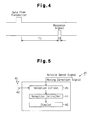
- the receiver 40 will now be described with reference to Fig. 5.
- the receiver 40 includes a reception controller 44, a reception circuit 45, and a display 46.
- the reception controller 44 processes data received with the reception antenna 41.
- the reception controller 44 which is, for example, a microcomputer, includes a CPU, a ROM, and a RAM.
- the reception circuit 45 receives data wirelessly transmitted by the transmitters 30 and response signals wirelessly transmitted by the repeaters 51, 52 through the reception antenna 41.
- the reception circuit 45 demodulates and decodes the received data and response signals, and sends the data and signals to the reception controller 44.
- the reception controller 44 determines which one of the tires 20 has sent a signal.
- the reception controller 44 receives a signal representing the speed of the vehicle 10, or a vehicle speed signal, from, for example, a speedometer (not shown) provided at a predetermined position in the vehicle 10.
- the reception controller 44 also receives a signal representing the direction of movement of the vehicle 10, or a moving direction signal, from, for example, a transmission (not shown) provided at a predetermined position in the vehicle 10.
- the transmission outputs a signal representing the position of the shift lever as the moving direction signal to the reception controller 44.
- the reception controller 44 determines whether the vehicle 10 is moving forward or backward.
- the reception controller 44 determines that the vehicle 10 is moving backward only when the shift lever is at the reverse position. When the shift lever is at a position other than the reverse position, the reception controller 44 determines that the vehicle 10 is moving forward.
- the reception controller 44 is capable of determining the rotating direction of the tires 20. Therefore, based on the acceleration data from the acceleration sensor 34, the vehicle speed signal, and the moving direction signal, the receiver 40 is capable of determining whether data has been sent from the tire 20 of one of the front and rear left wheels FL, RL or from the tire 20 of one of the front and rear right wheels FR, RR.
- the reception controller 44 stores information regarding the position of the tire 20 associated with the transmitter 30 that has sent a signal, for example, in the RAM. Specifically, when storing the information of the position of the tire 20 corresponding to the transmitter 30 that has sent a signal with the ID code, the reception controller 44 associates the information with the ID code contained in the received data.
- the reception controller 44 Based on the received data and the response signal, the reception controller 44 obtains the pressure and the temperature of the tire 20 that is associated with the transmitter 30 that is the source of the received data.
- the reception controller 44 causes the display 46 to display data related to the pressure and the temperature of the tire 20 associated with the transmitter 30 that is the source of the received data.
- the reception controller 44 also causes the display 46 to display the position of the tire 20 corresponding to the data. Particularly, when there is an abnormality in the pressure of the tire 20, the reception controller 44 displays warning on the display 46.
- the display 46 functions as notifying means.
- This embodiment has the following advantages.
- the repeaters 51, 52 shown in Fig. 1 may be replaced with a single repeater 53 shown in Fig. 1.
- the repeater 53 is provided at a position in the vehicle body frame 11 that is substantially at the midpoint between the rear wheels RL, RR. In this configuration, when receiving data from the transmitters 30 of the tires 20 of the rear left wheel RL and the rear right wheel RR, the repeater 53 transmits the response signal T2 after the predetermined period T1 has elapsed.
- the same advantages as the previous embodiment are obtained with the single repeater 53.
- the repeaters 51, 52 may be provided in the wheel wells of the front wheels FL, FR. In this configuration, based on whether the receiver 40 has received the response signal T2 from the repeaters 51, 52, the receiver 40 is capable of determining the tire 20 associated with the transmitter 30 that is the source of the received data.
- a single repeater 53 may be provided at a position in the vehicle body frame 11 that is substantially at the midpoint between the front wheels FL, FR.
- the repeaters 51 to 53 may be provided at any positions in the vehicle body frame 11. Specifically, the repeaters 51 to 53 may be provided in positions close to the tires 20, for example, in a front spoiler, a rear spoiler, a bumper, or a fender.
- the predetermined period T1 may be changed. Also, the time at which the response signal T2 is transmitted may be changed. Alternatively, a specific code may be transmitted as the response signal T2.
- the speed of the vehicle 10 may be determined according to the degree of the acceleration data from the acceleration sensors 34 as shown in Fig. 3(b). Specifically, the output value of the acceleration data is converted into the speed by an integration circuit to determine the speed of the vehicle 10. In this configuration, the rotation direction of the tires 20 is determined based on the speed of the vehicle 10 and a signal representing the position of the shift lever.
- the receiver 40 is capable of determining whether received data has been sent from the tire 20 of one of the front and rear left wheels FL, RL or from the tire 20 of one of the front and rear right wheels FR, RR.
- the abnormality When there is an abnormality in the pressure or the temperature of the tire 20, the abnormality may be indicated by a sound.
- a speaker that is mounted on the vehicle 10 in advance may be used as an informing device.
- the temperature sensor 33 may be omitted. In this case, the transmitter 30 has the minimum functions. This reduces the cost.
- Air pressure data transmitted by the transmitter 30 may indicate the value of the air pressure or whether the air pressure is within a permissible range.
- the present invention may be applied to two-wheeled vehicles, such as bicycles and motor cycles, multi-wheeled busses, multi-wheeled towed vehicles and industrial vehicles, such as forklifts.
- the receiver 40 and the display 46 are provided in the tractor.
Landscapes
- Engineering & Computer Science (AREA)
- Mechanical Engineering (AREA)
- Computer Networks & Wireless Communication (AREA)
- Arrangements For Transmission Of Measured Signals (AREA)
- Measuring Fluid Pressure (AREA)
Applications Claiming Priority (2)
| Application Number | Priority Date | Filing Date | Title |
|---|---|---|---|
| JP2002320207 | 2002-11-01 | ||
| JP2002320207A JP2004155222A (ja) | 2002-11-01 | 2002-11-01 | タイヤ状態監視装置 |
Publications (2)
| Publication Number | Publication Date |
|---|---|
| EP1445125A2 true EP1445125A2 (de) | 2004-08-11 |
| EP1445125A3 EP1445125A3 (de) | 2009-09-02 |
Family
ID=32652542
Family Applications (1)
| Application Number | Title | Priority Date | Filing Date |
|---|---|---|---|
| EP03021753A Withdrawn EP1445125A3 (de) | 2002-11-01 | 2003-09-25 | Reifenzustands- Überwachungsgerät |
Country Status (3)
| Country | Link |
|---|---|
| US (1) | US6885292B2 (de) |
| EP (1) | EP1445125A3 (de) |
| JP (1) | JP2004155222A (de) |
Cited By (2)
| Publication number | Priority date | Publication date | Assignee | Title |
|---|---|---|---|---|
| FR3049499A1 (fr) * | 2016-03-31 | 2017-10-06 | Continental Automotive France | Procede de communication entre une pluralite de modules electroniques de mesure d'un vehicule automobile |
| CN113103830A (zh) * | 2020-01-10 | 2021-07-13 | 比亚迪股份有限公司 | 胎压监测数据传输方法、装置、中继器单元及车辆 |
Families Citing this family (20)
| Publication number | Priority date | Publication date | Assignee | Title |
|---|---|---|---|---|
| FR2847667B1 (fr) * | 2002-11-22 | 2005-01-07 | Siemens Vdo Automotive | Dispositif de detection de la position d'une roue de vehicule |
| US7518495B2 (en) * | 2003-11-18 | 2009-04-14 | Lear Corporation | Universal tire pressure monitor |
| JP4937759B2 (ja) * | 2004-01-20 | 2012-05-23 | シュレイダー ブリッジポート インターナショナル インコーポレイテッド | 遠隔タイヤモニタシステムにおいてショックセンサを用いた動作検出方法 |
| JP2005321958A (ja) * | 2004-05-07 | 2005-11-17 | Denso Corp | タイヤ空気圧検出装置 |
| JP2006142873A (ja) * | 2004-11-16 | 2006-06-08 | Yazaki Corp | タイヤ空気圧監視装置及びタイヤ空気圧監視方法 |
| KR100596458B1 (ko) | 2004-12-01 | 2006-07-04 | 현대모비스 주식회사 | 타이어 압력 모니터링 시스템의 타이어 위치 감지 방법 |
| DE102006012535A1 (de) * | 2005-04-01 | 2006-10-19 | Continental Teves Ag & Co. Ohg | Reifenluftdrucküberwachungssystem sowie Verfahren zur Zuordnung von Reifenmodulen in einem Reifenluftdrucküberwachungssystem |
| US7382239B2 (en) * | 2005-08-23 | 2008-06-03 | Gm Global Technology Operations, Inc. | System and method for improving received signal strength for an in-vehicle wireless communication system |
| DE102006028411A1 (de) * | 2006-06-21 | 2007-12-27 | Robert Bosch Gmbh | Verfahren zur Reifenzustandserkennung |
| US20090033478A1 (en) | 2007-07-03 | 2009-02-05 | Continental Automotive Systems Us, Inc. | Universal tire pressure monitoring sensor |
| US8751092B2 (en) | 2011-01-13 | 2014-06-10 | Continental Automotive Systems, Inc. | Protocol protection |
| JP5447442B2 (ja) * | 2011-06-15 | 2014-03-19 | 株式会社デンソー | 車輪位置検出装置およびそれを備えたタイヤ空気圧検出装置 |
| US8502655B2 (en) | 2011-08-09 | 2013-08-06 | Continental Automotive Systems, Inc. | Protocol misinterpretation avoidance apparatus and method for a tire pressure monitoring system |
| US9676238B2 (en) | 2011-08-09 | 2017-06-13 | Continental Automotive Systems, Inc. | Tire pressure monitor system apparatus and method |
| CN103826879B (zh) | 2011-08-09 | 2017-10-10 | 大陆汽车系统公司 | 用于传输轮胎压力信号的设备和方法 |
| CN103874592B (zh) | 2011-08-09 | 2018-01-30 | 大陆汽车系统公司 | 用于激活轮胎压力监控器的定位过程的设备和方法 |
| CN103717416B (zh) | 2011-08-09 | 2019-02-22 | 大陆汽车系统公司 | 轮胎压力监控设备和方法 |
| US9446636B2 (en) | 2014-02-26 | 2016-09-20 | Continental Automotive Systems, Inc. | Pressure check tool and method of operating the same |
| US9517664B2 (en) | 2015-02-20 | 2016-12-13 | Continental Automotive Systems, Inc. | RF transmission method and apparatus in a tire pressure monitoring system |
| DE102016213290A1 (de) | 2015-08-03 | 2017-02-09 | Continental Automotive Systems, Inc. | Vorrichtung, System und Verfahren zum Konfigurieren eines Reifeninformationssensors mit einem Übertragungsprotokoll auf der Basis von Fahrzeugtriggerkenngrößen |
Family Cites Families (6)
| Publication number | Priority date | Publication date | Assignee | Title |
|---|---|---|---|---|
| DE3835236A1 (de) * | 1988-10-15 | 1990-04-19 | Bosch Gmbh Robert | Schaltungsanordnung zur reifendruck- und temperatur-ueberwachung |
| US5473938A (en) * | 1993-08-03 | 1995-12-12 | Mclaughlin Electronics | Method and system for monitoring a parameter of a vehicle tire |
| JPH10104103A (ja) | 1996-09-18 | 1998-04-24 | Alpha Beta Electron Ag | タイヤ圧モニタリング装置 |
| US6204758B1 (en) * | 1999-07-23 | 2001-03-20 | Schrader-Bridgeport International, Inc. | System to automatically determine wheel position for automotive remote tire monitoring system |
| US6362731B1 (en) * | 2000-12-06 | 2002-03-26 | Eaton Corporation | Tire pressure monitor and location identification system and method |
| US6725712B1 (en) * | 2002-03-01 | 2004-04-27 | Lear Corporation | System and method for tire pressure monitoring with automatic tire location recognition |
-
2002
- 2002-11-01 JP JP2002320207A patent/JP2004155222A/ja active Pending
-
2003
- 2003-09-24 US US10/677,652 patent/US6885292B2/en not_active Expired - Fee Related
- 2003-09-25 EP EP03021753A patent/EP1445125A3/de not_active Withdrawn
Cited By (3)
| Publication number | Priority date | Publication date | Assignee | Title |
|---|---|---|---|---|
| FR3049499A1 (fr) * | 2016-03-31 | 2017-10-06 | Continental Automotive France | Procede de communication entre une pluralite de modules electroniques de mesure d'un vehicule automobile |
| US10226973B2 (en) | 2016-03-31 | 2019-03-12 | Continental Automotive France | Communication method between a plurality of electronic measurement modules of a motor vehicle |
| CN113103830A (zh) * | 2020-01-10 | 2021-07-13 | 比亚迪股份有限公司 | 胎压监测数据传输方法、装置、中继器单元及车辆 |
Also Published As
| Publication number | Publication date |
|---|---|
| US6885292B2 (en) | 2005-04-26 |
| US20040155761A1 (en) | 2004-08-12 |
| JP2004155222A (ja) | 2004-06-03 |
| EP1445125A3 (de) | 2009-09-02 |
Similar Documents
| Publication | Publication Date | Title |
|---|---|---|
| US6983649B2 (en) | Tire condition monitoring apparatus | |
| US6885292B2 (en) | Tire condition monitoring apparatus | |
| EP1524133B1 (de) | Sender für ein Reifenzustandsüberwachungsgerät | |
| US6963274B2 (en) | Transmitter of tire condition monitoring apparatus and tire condition monitoring apparatus | |
| EP1452349A2 (de) | Sender eines Reifenzustandsüberwachungsgerätes und Reifenzustandsüberwachungsgerät | |
| US7253726B2 (en) | Tire condition monitoring apparatus, transmitter, and receiver | |
| EP1419907B1 (de) | Reifenzustandsüberwachungsgerät | |
| US20030107481A1 (en) | Tire condition monitoring apparatus and method | |
| EP1468847B1 (de) | Reifenzustandsüberwachungsgerät | |
| EP1428693B1 (de) | Transponder für Reifenzustandsüberwachungsgerät | |
| EP1486357A1 (de) | Transmitter of tire condition monitoring apparatus and tire condition monitoring apparatus | |
| US7116217B2 (en) | Transmitter and receiver for tire condition monitoring apparatus | |
| EP1433626A2 (de) | Reifenzustandüberwachungsgerät | |
| US8296006B2 (en) | Tire pressure monitoring device | |
| JP2006327324A (ja) | タイヤ状態監視装置 |
Legal Events
| Date | Code | Title | Description |
|---|---|---|---|
| PUAI | Public reference made under article 153(3) epc to a published international application that has entered the european phase |
Free format text: ORIGINAL CODE: 0009012 |
|
| AK | Designated contracting states |
Kind code of ref document: A2 Designated state(s): AT BE BG CH CY CZ DE DK EE ES FI FR GB GR HU IE IT LI LU MC NL PT RO SE SI SK TR |
|
| AX | Request for extension of the european patent |
Extension state: AL LT LV MK |
|
| PUAL | Search report despatched |
Free format text: ORIGINAL CODE: 0009013 |
|
| AK | Designated contracting states |
Kind code of ref document: A3 Designated state(s): AT BE BG CH CY CZ DE DK EE ES FI FR GB GR HU IE IT LI LU MC NL PT RO SE SI SK TR |
|
| AX | Request for extension of the european patent |
Extension state: AL LT LV MK |
|
| AKX | Designation fees paid | ||
| STAA | Information on the status of an ep patent application or granted ep patent |
Free format text: STATUS: THE APPLICATION IS DEEMED TO BE WITHDRAWN |
|
| 18D | Application deemed to be withdrawn |
Effective date: 20100303 |
|
| REG | Reference to a national code |
Ref country code: DE Ref legal event code: 8566 |