EP1445138B1 - Support élastique, en particulier en forme de cale, et chassis - Google Patents
Support élastique, en particulier en forme de cale, et chassis Download PDFInfo
- Publication number
- EP1445138B1 EP1445138B1 EP04000719A EP04000719A EP1445138B1 EP 1445138 B1 EP1445138 B1 EP 1445138B1 EP 04000719 A EP04000719 A EP 04000719A EP 04000719 A EP04000719 A EP 04000719A EP 1445138 B1 EP1445138 B1 EP 1445138B1
- Authority
- EP
- European Patent Office
- Prior art keywords
- bearing
- inner part
- outer part
- partial region
- frame
- Prior art date
- Legal status (The legal status is an assumption and is not a legal conclusion. Google has not performed a legal analysis and makes no representation as to the accuracy of the status listed.)
- Revoked
Links
Images
Classifications
-
- B—PERFORMING OPERATIONS; TRANSPORTING
- B61—RAILWAYS
- B61C—LOCOMOTIVES; MOTOR RAILCARS
- B61C9/00—Locomotives or motor railcars characterised by the type of transmission system used; Transmission systems specially adapted for locomotives or motor railcars
- B61C9/38—Transmission systems in or for locomotives or motor railcars with electric motor propulsion
- B61C9/48—Transmission systems in or for locomotives or motor railcars with electric motor propulsion with motors supported on vehicle frames and driving axles, e.g. axle or nose suspension
-
- F—MECHANICAL ENGINEERING; LIGHTING; HEATING; WEAPONS; BLASTING
- F16—ENGINEERING ELEMENTS AND UNITS; GENERAL MEASURES FOR PRODUCING AND MAINTAINING EFFECTIVE FUNCTIONING OF MACHINES OR INSTALLATIONS; THERMAL INSULATION IN GENERAL
- F16F—SPRINGS; SHOCK-ABSORBERS; MEANS FOR DAMPING VIBRATION
- F16F1/00—Springs
- F16F1/36—Springs made of rubber or other material having high internal friction, e.g. thermoplastic elastomers
- F16F1/42—Springs made of rubber or other material having high internal friction, e.g. thermoplastic elastomers characterised by the mode of stressing
- F16F1/52—Springs made of rubber or other material having high internal friction, e.g. thermoplastic elastomers characterised by the mode of stressing loaded in combined stresses
- F16F1/54—Springs made of rubber or other material having high internal friction, e.g. thermoplastic elastomers characterised by the mode of stressing loaded in combined stresses loaded in compression and shear
Definitions
- the invention relates to a bearing, in particular a wedge bearing for the storage of a Frame on a stationary component in a vehicle; especially Rail vehicle, in detail with the features of the preamble of Claim 1; also a frame.
- a wedge bearing which is a so-called rubber-metal component in the form of an inner part comprises, between in the same direction, preferably parallel-sided metal parts in the form of an outer part is arranged and adherent connected, on push or push claimed rubber bodies.
- the connection is via Adhesive process, d. H. scorching is also possible. Own the outer part forming metal parts inclined to the vertical direction and preferably parallel adhesive surfaces for the introduction of the rubber body, wherein the Adhesive surfaces also curved in itself or at a certain angle to each other can be inclined.
- the outer part is made in several parts, which results in a required separate connection of each individual part.
- a wedge bearing in the form a vibration damper with progressive spring characteristic previously known, which an outer part for connection to the forces supporting components comprises and further an inner part which is enclosed by the outer part.
- the inner part is as Metal part executed and executed at the lower and upper edge crowned.
- Rubber segments provided between the inner part and the outer part are arranged. These are arranged distributed in the circumferential direction around the inner wedge and further in the state of the arrangement of the inner part in the outer part enclosed area vulcanized to the outer part and the inner part. A releasable connection is not given. Again, in case of failure or in case damage to the bearing requires replacement of the entire bearing.
- the invention is therefore based on the object, a warehouse for the storage of Frame on connection components, in particular car bodies of To develop rail vehicles, which is inexpensive by simple means dimensionable and yet easy to assemble and maintain. It is in particular to a simple interchangeability, even of individual elements, remedy.
- the inventively designed bearing in particular wedge bearing comprises at least two sub-elements - an inner part for receiving a bearing pin or other Element and an inner part at least partially based on the axis of the Arrangement of the bearing pin circumferentially enclosing outer part.
- the Bearing is free from a bearing housing.
- the outer part thus forms the system directly or stop and connection surfaces when coupled with a Ranbauelement when used in rail vehicles, for example at Storage of the frame of the car body.
- According to the invention are inner part and External part detachably connected to each other. This means that at any time also in the assembled state separation of both elements is possible from each other.
- the Outer part comprises at least two partial areas - a first partial area, which the Stop and contact surfaces when connecting the bearing with the Terminal component forms and a second portion which is connected to the first Opera Schl
- the inner part at least partially based on the axis of the Bearing in the circumferential direction encloses.
- the investment and contact surfaces for Connection with a terminal component are arranged on the outer part. This is doing from below to the terminal component, in particular the Longitudinal profiles of the car body when using for storage of a frame in mounted on a rail vehicle.
- the outer part is so direct and property typical without auxiliary housing with the connection component connectable.
- the term investment and contact surfaces are the surface areas understood in the realization of a detachable connection with the Connection component come to this concern and in the area of the Connecting elements or the required environment for the Connecting elements, for example through holes etc. are arranged.
- at least one elastic element with a rigidity in a range of 500 to 10,000 N / mm inclusive arranged, preferably a rubber package.
- the elastic element either forms with the inner part of an integral unit or exists as a separate element that as Intermediate element executed and as this between inner part and outer part is inserted or joined together with the inner part to form a structural unit is.
- a tapered curved sheet which is disposed between the inner part and the outer part and the inner part and the or the elastic elements at least partially related in the circumferential direction enclosing the bearing axis for receiving the bearing pin on the inner part.
- the conically curved sheet metal is designed in such a way that that this is adapted with its outer contour to the inner contour of the outer part and at least with the vertically oriented sheet metal areas Jamming between outer part and inner part or the unit made of sheet metal, Rubber package and inner part allows.
- the detachable connection between inner part and outer part is achieved either by force or positive connection or a combination of both realized.
- the connection can doing so, for example, by jamming or choosing the appropriate Connecting elements are made. In the first case, this will be a fit provided between the inner part and outer part, while in the second case for example, the coupling directly using fasteners, For example, screw is done.
- the connection of the inner part with the outer part via the tapered bent sheet, which between the inner part and outer part is arranged and by means of screw on the first part of the area opposite end face of the second portion is connected to the outer part.
- the conical sheet is formed to form a gap in vertical direction between the outer part in the second portion and the inner part to Recording a stop block between these two components arranged. About this extreme loads can be absorbed in the vertical direction become.
- the investment and contact surfaces are preferably surface areas on the facing away from the inner part end face of the first portion of the outer part directly educated.
- According to a particularly advantageous embodiment is on the outer part in first subsection centrally arranged an undercut for the realization of a provided positive connection with a connection component. It will It is also possible to transfer large loads in the longitudinal direction.
- the inner part is provided with a recess, preferably in the form of a Passage opening provided for receiving a bearing pin.
- a bearing pin Preferably be in this extremely large bearing pin with a diameter greater than 40 mm, preferably greater than 50 mm provided.
- the solution according to the invention enables dynamic forces in longitudinal, transverse and / or vertical direction within the bearing characteristic soft without stop take. To absorb extreme loads, according to the Use case additional stops are provided.
- the bearing according to the invention is particularly suitable for use for storage a frame on a connection component, in particular a car body in a rail vehicle.
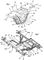
- FIG. 1 is a perspective view of an inventively designed bearing 1, in particular wedge bearing 2.
- This is at least two parts, comprises at least an inner part 3 for receiving a bearing pin and the inner part 3 enclosing the outer part 4 and is preferably in terms of geometry by a substantially symmetrical structure in both the longitudinal and transverse directions LR and QR characterized.
- the directional information longitudinal direction LR and transverse direction QR are illustrated by arrows and refer to the installation position usually required when using the bearing 1 in a rail vehicle for the storage of cross members.
- a recess 5 is provided on the inner part 3.
- This is preferably formed as a through hole 6, which is adapted to the geometry of the bearing pin with respect to the geometric shape or the cross section, which is designed in the illustrated case as a through hole with a circular cross section, which is characterized by an axis A 6 .
- the inner part 3 is reversibly connected to the outer part 4.
- the connection can be generated by force and / or positive connection, such as screw or clamp connections.
- the bearing 1 is free of a bearing housing.
- the function of the abutment and contact surfaces 8 for connecting the bearing 1 with another component, for example, when using the bearing 1 for mounting a frame in a rail vehicle to a car body, is taken over by the outer part 4. Ie. the outer part 4 is directly and property typical to mount without auxiliary housing to the longitudinal profiles of the car body.
- the outer part 4 comprises for this purpose at least two partial areas 7.1 and 7.2, which together form a structural unit, wherein the outer part 4 is preferably made in one piece.
- the first portion 7.1 forms the contact and contact surfaces 8 for conditioning of the bearing 1 on a component. These are preferably arranged in a plane which is arranged parallel to a plane arranged by the axis A6 and a perpendicular thereto in the horizontal plane plane. If supporting elements or bearing bolts running or oriented in the transverse direction are mounted in the inner part 3, the alignment of the first partial area 7.1 takes place in the longitudinal direction. This means that the first subregion 7.1 extends on both sides with respect to a vertical A S in the vertical direction to the axis A 6 .
- connection of the first and second sub-areas 7.1 and 7.2 is characterized by a cross-sectionally substantially wedge-shaped recess 10, in particular through opening 11, which serves to surround the inner part 3.
- the second portion 7.2 is preferably designed v-shaped, with the possibility also only the recess 10 to make such regardless of the outer periphery 18 characterizing geometry. Since the inner part 3 is enveloped or surrounded by the outer part 4, a Noten is achieved by positive locking even in case of failure of a component.
- an undercut 12 For transmitting larger loads, in particular in the longitudinal direction is on the outer part 4, In particular, in the partial area 7. 1 centrally provided an undercut 12, the one enables positive connection with the component on which the in the camp. 1 To articulate to be stored component is.
- the undercut 12 forms at least two Stop surfaces 13.1 and 13.2 for the realization of a positive connection, for example with the car body in the longitudinal direction.
- elastic elements 14.1, 14.2 which are preferably in the form of rubber packages are formed, provided.
- the reversible, d. H. releasable connection is made by Provision of a corresponding to the inner contour of the outer part 4 bent tapered metal sheet 17, which between inner part 3 and inner circumference is arranged and from below, d. H. in section 7.2 with this and the inner part 3 is screwed, for example. Another possibility is jamming, this is additionally secured by fastening means.
- the elastic Elements 14.1 and 14.2 are then between inner part 3 and conical plate 17th arranged. These can be present as separate elements or with the Connected inside part 3, for example, be vulcanized to this.
- the inventively designed bearing 1 it is possible dynamic forces both in the longitudinal and transverse directions and vertical direction within the Take stock characteristic smoothly without stop. Extreme loads can through a over the production dimension in the longitudinal direction adjustable stop 19 and a not shown insertable pressure plate in the vertical direction in the Interspace 20 between plate 17 and inner part 3, which in the vertical direction the front side facing away from the first portion 7.1 7.1 of the inner part limited is, and a set to measure and also not shown side bolted stop bracket in the transverse direction, the setting depends on en present boundary conditions, transferred in each load direction become.
- the stop 19 may further by material integration in the outer part 4 are formed.
- FIG. 2 illustrates in a schematically simplified illustration with reference to FIG Basic structure of a frame 21 the basic principle of a two-stage Storage concept of drive units using the Inventively designed bearing 1.
- the frame 21 comprises at least two Cross member 22 and 23 for articulation of the frame 21 when used in vehicles for example, to a car body, wherein the cross member 22 and 23 via at least one longitudinal member 44 are connected to each other.
- the cross member 22 is designed as a main cross member 25, while the cross member 23 has the function the secondary cross member 26 takes over.
- the main mass M to be stored becomes which is for example the prime mover or a unit Prime mover and transmission, d. H.
- the secondary Bearings D1 and D2 serve to support the main cross member 25, For example, on a car body when used in rail vehicles and thus indirectly the storage of the main mass M at this.
- the bearings D1 and D2 are preferably in the end regions E1 and E2 of the main cross member 25 this assigned or store this. This applies analogously also for the Secondary cross member 26.
- the two secondary side bearings D3 and D4 also the transversely to the direction of travel in a warehouse considered outer Assigned dimensions of the secondary cross member 26, that is, the end portions E3 and E4.
- the bearing pins B1 to B4 are positive and / or non-positive and / or cohesively with the corresponding cross member - main cross member 25th or secondary cross member 26 - connected or form a structural unit with this.
- the side member 24 includes at least two side rail members 27 and 28, the parallel in the longitudinal direction of the frame 21, when installed in the vehicle preferably extend parallel to the direction of travel axis and the connection serve between the main cross member 25 and the sub-cross member 26, wherein the Linkage of the side member members 27 and 28 to the individual cross member 22 and 23 takes place symmetrically.
- the main cross member 25 serves to accommodate and transfer of the main load in all directions during the secondary crossbeam 26 for receiving the supporting forces of the main mass M, in particular the motor-gear unit as well as the main part of the mass forces from auxiliary or Additional units is used.
- the longitudinal member 24, in particular the longitudinal support elements 27, 28 are formed in the longitudinal direction continuously over the extent thereof.
- the side rail members 27 and 28 are defined bent and form a mounting and assembly plane 29 for the Main mass M or for articulation of an auxiliary frame 30 for storage the main mass M.
- the bend is formed such that the connection 31 and 32 of the longitudinal member 24, in particular the longitudinal support elements 27 and 28 with the Main cross member 25 in the through the main cross member 25 and a vertical in Longitudinally formed to level 33 takes place.
- the compound 31 or 32 of Longitudinal support elements 27 and 28 with the main cross member 25 takes place preferably rigid.
- connection of the mounting and assembly plane 29 at the secondary cross member 26 takes place with the interposition of support beams 35 and 36, which are each associated with one of the side member members 27 and 28 and connect the side rail members 27 and 28 to the secondary cross member 26.
- the connection is elastic, so that here an adapted elastic connection between the longitudinal member 24 and secondary cross member 26 is possible.
- This can in the connection between the longitudinal support elements 27 and 28th and the support beams 35 and 36 at the same time rigid connection of Support beams 35 and 36 to the secondary cross member 26 or through rigid connection of the longitudinal support members 27 and 28 to the support beams 35 and 36 and elastic connection of the support beams 35 and 36 to the secondary cross member 26th respectively.
- compounds 37 and 38 are between Stauereben- and side rail members 27 and 28 executed elastic.
- This Solution be the individual secondary suspension points of the frame 21st forming support frame not directly connected, so quasi supported.
- Bending of the longitudinal member 24 may be a bending deformation on the entire free Length take place, therefore, the amount of at least on the span between Main and secondary cross member 25 and 26 acts.
- it will a decoupling of the load and the forces between the main and Subcarriers 25 and 26 scored, as necessary for the transmission of power Lagerweg taken by the flexible side rail members 27 and 28 partially and compensated.
- the main mass M which is formed for example by a motor-gear unit is defined according to the invention stored in three places. These are with A, B and C denotes and define so-called load introduction points. Define A and B while the load instructions in the main carrier. Because the focus of the stored Mass M is close to the connecting axis between the bearings A and B, is in accordance with the leverage ratios of the main part of the vertical load in introduced the main cross member 25.
- the loads arising at the depository C are on the longitudinal support members 27, 28, the near-side support 26 in the local same area viewed in the longitudinal direction via support beams 35, 36 connected are to be deduced.
Landscapes
- Engineering & Computer Science (AREA)
- General Engineering & Computer Science (AREA)
- Mechanical Engineering (AREA)
- Combustion & Propulsion (AREA)
- Child & Adolescent Psychology (AREA)
- Chemical & Material Sciences (AREA)
- Health & Medical Sciences (AREA)
- Transportation (AREA)
- Body Structure For Vehicles (AREA)
- Support Of The Bearing (AREA)
- Vibration Prevention Devices (AREA)
- Clamps And Clips (AREA)
- Installation Of Indoor Wiring (AREA)
- Spinning Or Twisting Of Yarns (AREA)
Claims (15)
- Palier (1), en particulier palier à coin (2),1.1 avec au moins deux parties : une partie intérieure (3) destinée à recevoir une broche de palier et une partie extérieure (4) entourant au moins partiellement la partie intérieure (3) ;1.2 la partie intérieure (3) et la partie extérieure (4) sont reliées l'une à l'autre de façon amovible ;1.3 le roulement (1) ne possède pas de boítier ;1.4 la partie extérieure (4) comprend au moins deux segments : un premier segment (7.1) qui forme les surfaces de butée et de contact (13.1, 13.2) lors de l'assemblage du roulement (1) avec un élément de raccordement, et un second segment (7.2) qui, avec le premier segment (7.1), entoure au moins partiellement la partie intérieure (3) dans le sens de la circonférence par rapport à l'axe de la broche de palier ;1.5 les surfaces d'appui et de contact (8) pour l'assemblage avec un élément de raccordement sont disposées sur la partie extérieure (4) ;1.6 avec au moins un élément élastique (14.1, 14.2) disposé entre la partie intérieure (3) et la partie extérieure (4) et ayant une rigidité comprise entre 500 N/mm et 10.000 N/mm inclus ;1.7 l'assemblage de la partie intérieure (3) avec la partie extérieure (4) est réalisé à l'aide d'un élément courbe conique, en particulier une tôle (17), qui est disposé entre la partie intérieure (3) et la partie extérieure (4).
- Palier (1) selon la revendication 1, caractérisé en ce que la partie extérieure (4) entoure complètement la partie intérieure (3) dans le sens de la circonférence.
- Palier (1) selon l'une quelconque des revendications 1 ou 2, caractérisé en ce que les surfaces d'appui et de contact (8) sont formées par des zones de surface sur la face du premier segment (7.1) de la partie extérieure (4) orientée à l'opposé de la partie intérieure (3).
- Palier (1) selon l'une quelconque des revendications 1 à 3, caractérisé en ce qu'il est prévu sur la partie extérieure (4) au milieu du premier segment (7.1) une dépouille (12) destinée à réaliser un assemblage par engagement de forme avec un premier élément de raccordement.
- Palier (1) selon l'une quelconque des revendications 1 à 4, caractérisé en ce que l'élément élastique (14.1, 14.2) est réalisé comme un paquet de caoutchouc.
- Palier (1) selon l'une quelconque des revendications 1 à 5, caractérisé en ce que l'élément élastique (14.1, 14.2) forme avec la partie intérieure (3) une unité de construction.
- Palier (1) selon la revendication 6, caractérisé en ce que l'élément élastique (14.1, 14.2) est fixé par vulcanisation sur la partie intérieure (3) ou l'élément (17), qui entoure au moins partiellement dans le sens de la circonférence la partie intérieure (3) et l'élément élastique (14.1, 14.2).
- Palier (1) selon l'une quelconque des revendications 1 à 7, caractérisé en ce que la partie intérieure (3) ou l'unité formée de la partie intérieure (3) et de l'élément en cône (17) est assemblée par emboítement avec la partie extérieure (4).
- Palier (1) selon l'une quelconque des revendications 1 à 8, caractérisé en ce que la partie intérieure (3) est reliée à la partie extérieure (4) par des moyens de fixation disposés au niveau de l'élément élastique (14.1, 14.2).
- Palier (1) selon l'une quelconque des revendications 1 à 9, caractérisé en ce que:10.1 la tôle conique (17) est fixée sur la partie extérieure (4) au moyen de vis sur la face du second segment (7.2) orientée à l'opposé du premier segment (7.1).
- Palier (1) selon l'une quelconque des revendications 1 à 10, caractérisé en ce que la tôle conique (17) forme avec la partie intérieure (3) une unité de construction.
- Palier (1) selon l'une quelconque des revendications 1 à 11, caractérisé en ce que la tôle conique (17) est disposée, en formant un espace intermédiaire (20), dans le sens vertical entre la partie extérieure (4) dans le second segment (7.2) et la partie intérieure (3) pour recevoir un sabot de butée entre ces deux éléments.
- Palier (1) selon l'une quelconque des revendications 1 à 12, caractérisé en ce que la partie extérieure (4) forme dans le sens longitudinal sur sa circonférence intérieure entourant la partie intérieure (3), grâce au choix de la tolérance de fabrication, une butée (19) dans le sens vertical et/ou longitudinal.
- Palier (1) selon l'une quelconque des revendications 1 à 13, caractérisé en ce qu'il est prévu une butée dans le sens transversal qui est formée par un étrier vissé sur la partie extérieure (4) ou formé solidaire de celle-ci.
- Châssis (21)15.1 avec au moins deux traverses (22, 23, 25, 26) reliées entre elles par un longeron (24) en formant un plan de montage et/ou de disposition (29) décalé verticalement par rapport aux traverses pour la masse principale (M) ;15.2 la masse principale (M) est principalement supportée dans le châssis (21) ;15.3 avec des paliers (D1, D2, D3, D4) associés aux traverses (22, 23, 25, 26) servant à la liaison du bâti avec un élément de raccordement, en particulier une caisse de véhicule, selon l'une quelconque des revendications 1 à 14.
Applications Claiming Priority (2)
| Application Number | Priority Date | Filing Date | Title |
|---|---|---|---|
| DE10301916 | 2003-01-17 | ||
| DE10301916A DE10301916A1 (de) | 2003-01-17 | 2003-01-17 | Lager, insbesondere Keillager und Rahmen |
Publications (4)
| Publication Number | Publication Date |
|---|---|
| EP1445138A2 EP1445138A2 (fr) | 2004-08-11 |
| EP1445138A3 EP1445138A3 (fr) | 2004-08-18 |
| EP1445138B1 true EP1445138B1 (fr) | 2005-11-23 |
| EP1445138B8 EP1445138B8 (fr) | 2006-04-26 |
Family
ID=32602751
Family Applications (1)
| Application Number | Title | Priority Date | Filing Date |
|---|---|---|---|
| EP04000719A Revoked EP1445138B8 (fr) | 2003-01-17 | 2004-01-15 | Support élastique, en particulier en forme de cale, et chassis |
Country Status (4)
| Country | Link |
|---|---|
| EP (1) | EP1445138B8 (fr) |
| AT (1) | ATE310652T1 (fr) |
| DE (2) | DE10301916A1 (fr) |
| ES (1) | ES2250926T3 (fr) |
Cited By (1)
| Publication number | Priority date | Publication date | Assignee | Title |
|---|---|---|---|---|
| WO2025061545A1 (fr) * | 2023-09-18 | 2025-03-27 | Siemens Mobility Austria Gmbh | Palier à coin |
Families Citing this family (1)
| Publication number | Priority date | Publication date | Assignee | Title |
|---|---|---|---|---|
| CN102371881B (zh) * | 2010-08-13 | 2015-06-17 | 上海汽车集团股份有限公司 | 动力总成支撑系统 |
Family Cites Families (10)
| Publication number | Priority date | Publication date | Assignee | Title |
|---|---|---|---|---|
| DE1813156B2 (de) * | 1968-12-06 | 1972-08-24 | Getefo Gesellschaft für technischen Fortschritt mbH, 5410 Höhr-Grenzhausen | Als keillager ausgebildetes gummimetallbauteil |
| DE8521933U1 (de) * | 1985-07-30 | 1986-10-30 | Adam Opel AG, 6090 Rüsselsheim | Triebwerksaufhängung |
| DE3610216A1 (de) * | 1986-03-26 | 1987-10-01 | Duewag Ag | Fahrzeug, insbesondere schienenfahrzeug |
| DE3630360A1 (de) * | 1986-09-05 | 1988-03-17 | Metzeler Kautschuk | Lager zur elastischen abstuetzung von maschinen |
| DE4009995C3 (de) * | 1990-03-02 | 1999-02-11 | Metzeler Gimetall Ag | Verfahren zur schwingungsisolierenden Lagerung einer Motor-Getriebeeinheit und Lagerung nach diesem Verfahren |
| DE4009828A1 (de) * | 1990-03-27 | 1991-10-02 | Metzeler Gimetall Ag | Elastisches motorlager in form eines keillagers |
| DE4322126C2 (de) * | 1993-07-02 | 1995-06-29 | Metzeler Gimetall Ag | Elastisches Lager |
| DE19536737A1 (de) * | 1995-09-23 | 1997-03-27 | Ivm Engineering Joint Venture | Schwingungsdämpfer mit progressiver Federkennlinie und geringer inneren Reibung in integrierter Bauweise |
| US6450474B1 (en) * | 2000-03-09 | 2002-09-17 | Lord Corporation | X-configuration engine mounting with locking end plates |
| DE10061127A1 (de) * | 2000-12-07 | 2002-06-27 | Voith Turbo Kg | Rahmenbaureihe |
-
2003
- 2003-01-17 DE DE10301916A patent/DE10301916A1/de not_active Withdrawn
-
2004
- 2004-01-15 AT AT04000719T patent/ATE310652T1/de not_active IP Right Cessation
- 2004-01-15 DE DE502004000138T patent/DE502004000138D1/de not_active Expired - Lifetime
- 2004-01-15 ES ES04000719T patent/ES2250926T3/es not_active Expired - Lifetime
- 2004-01-15 EP EP04000719A patent/EP1445138B8/fr not_active Revoked
Cited By (1)
| Publication number | Priority date | Publication date | Assignee | Title |
|---|---|---|---|---|
| WO2025061545A1 (fr) * | 2023-09-18 | 2025-03-27 | Siemens Mobility Austria Gmbh | Palier à coin |
Also Published As
| Publication number | Publication date |
|---|---|
| EP1445138A3 (fr) | 2004-08-18 |
| ES2250926T3 (es) | 2006-04-16 |
| EP1445138B8 (fr) | 2006-04-26 |
| ATE310652T1 (de) | 2005-12-15 |
| DE10301916A1 (de) | 2004-08-05 |
| EP1445138A2 (fr) | 2004-08-11 |
| DE502004000138D1 (de) | 2005-12-29 |
Similar Documents
| Publication | Publication Date | Title |
|---|---|---|
| EP3009323B1 (fr) | Châssis d'un véhicule ferroviaire | |
| DE19703951C2 (de) | Vorderteilkonstruktion einer Fahrzeugkarosserie | |
| DE112017005369B4 (de) | Fahrzeugrahmen-stützapparat | |
| WO2011085773A1 (fr) | Douille de serrage excentrique | |
| DE69704742T2 (de) | Achsenkonstruktion für Fahrzeuge und Achseneingriffsplatte und Spannplatte dafür | |
| DE69924942T2 (de) | Blattfedergelenklager und Anordnung mit verstellbarem Führungselement | |
| DE4128488A1 (de) | Doppelquerlenker-vorderachsfuehrung | |
| DE102018122577A1 (de) | Verbindungssystem, Kupplungssystem und Verfahren zur Verbindung eines Zugfahrzeugs mit einem Auflieger | |
| DE19528745A1 (de) | Fahrzeug-Antriebsachse | |
| DE102017218796B4 (de) | Achsaufhängung | |
| DE102020128606A1 (de) | Vorrichtung zum Lagern einer radführenden Querblattfeder eines Fahrzeuges | |
| EP3707401B1 (fr) | Dispositif de couplage | |
| EP1445138B1 (fr) | Support élastique, en particulier en forme de cale, et chassis | |
| WO2013034371A2 (fr) | Dispositif d'entraînement pour un véhicule électrique et procédé pour fixer un dispositif d'entraînement dans un véhicule électrique | |
| EP2882631B1 (fr) | Colonne de direction d'un véhicule | |
| DE102018200323B4 (de) | Blattfederanordnung für Kraftfahrzeuge | |
| DE102012017319B4 (de) | Befestigungsanordnung zwischen einem Radiallager und einem Stützarm | |
| AT502802B1 (de) | Querträgerverbund für ein luftgefedertes nutzfahrzeug | |
| EP1057716A1 (fr) | Construction d'essieu pour véhicules utilitaires, leurs remorques et semi-remorques | |
| EP1710149B2 (fr) | Traverse terminale pour véhicule utilitaire | |
| EP1670672A1 (fr) | Element de fixation d'un ensemble destine a un vehicule automobile | |
| DE10301910B3 (de) | Rahmen | |
| DE102006055128B4 (de) | Elastisches Lager, insbesondere Getriebelager | |
| DE10301913B4 (de) | Rahmen | |
| DE102008026705B4 (de) | Motorrad mit einer Hinterradlagerung und einer Dämpfungseinrichtung zur Dämpfung von Pendelschwingungen |
Legal Events
| Date | Code | Title | Description |
|---|---|---|---|
| PUAI | Public reference made under article 153(3) epc to a published international application that has entered the european phase |
Free format text: ORIGINAL CODE: 0009012 |
|
| PUAL | Search report despatched |
Free format text: ORIGINAL CODE: 0009013 |
|
| AK | Designated contracting states |
Kind code of ref document: A2 Designated state(s): AT BE BG CH CY CZ DE DK EE ES FI FR GB GR HU IE IT LI LU MC NL PT RO SE SI SK TR |
|
| AX | Request for extension of the european patent |
Extension state: AL LT LV MK |
|
| AK | Designated contracting states |
Kind code of ref document: A3 Designated state(s): AT BE BG CH CY CZ DE DK EE ES FI FR GB GR HU IE IT LI LU MC NL PT RO SE SI SK TR |
|
| AX | Request for extension of the european patent |
Extension state: AL LT LV MK |
|
| 17P | Request for examination filed |
Effective date: 20050203 |
|
| AKX | Designation fees paid |
Designated state(s): AT BE BG CH CY CZ DE DK EE ES FI FR GB GR HU IE IT LI LU MC NL PT RO SE SI SK TR |
|
| GRAP | Despatch of communication of intention to grant a patent |
Free format text: ORIGINAL CODE: EPIDOSNIGR1 |
|
| GRAS | Grant fee paid |
Free format text: ORIGINAL CODE: EPIDOSNIGR3 |
|
| GRAA | (expected) grant |
Free format text: ORIGINAL CODE: 0009210 |
|
| AK | Designated contracting states |
Kind code of ref document: B1 Designated state(s): AT BE BG CH CY CZ DE DK EE ES FI FR GB GR HU IE IT LI LU MC NL PT RO SE SI SK TR |
|
| PG25 | Lapsed in a contracting state [announced via postgrant information from national office to epo] |
Ref country code: SI Free format text: LAPSE BECAUSE OF FAILURE TO SUBMIT A TRANSLATION OF THE DESCRIPTION OR TO PAY THE FEE WITHIN THE PRESCRIBED TIME-LIMIT Effective date: 20051123 Ref country code: RO Free format text: LAPSE BECAUSE OF FAILURE TO SUBMIT A TRANSLATION OF THE DESCRIPTION OR TO PAY THE FEE WITHIN THE PRESCRIBED TIME-LIMIT Effective date: 20051123 Ref country code: IE Free format text: LAPSE BECAUSE OF FAILURE TO SUBMIT A TRANSLATION OF THE DESCRIPTION OR TO PAY THE FEE WITHIN THE PRESCRIBED TIME-LIMIT Effective date: 20051123 Ref country code: SK Free format text: LAPSE BECAUSE OF FAILURE TO SUBMIT A TRANSLATION OF THE DESCRIPTION OR TO PAY THE FEE WITHIN THE PRESCRIBED TIME-LIMIT Effective date: 20051123 Ref country code: NL Free format text: LAPSE BECAUSE OF FAILURE TO SUBMIT A TRANSLATION OF THE DESCRIPTION OR TO PAY THE FEE WITHIN THE PRESCRIBED TIME-LIMIT Effective date: 20051123 Ref country code: FI Free format text: LAPSE BECAUSE OF FAILURE TO SUBMIT A TRANSLATION OF THE DESCRIPTION OR TO PAY THE FEE WITHIN THE PRESCRIBED TIME-LIMIT Effective date: 20051123 |
|
| REG | Reference to a national code |
Ref country code: GB Ref legal event code: FG4D Free format text: NOT ENGLISH |
|
| REG | Reference to a national code |
Ref country code: CH Ref legal event code: EP |
|
| REF | Corresponds to: |
Ref document number: 502004000138 Country of ref document: DE Date of ref document: 20051229 Kind code of ref document: P |
|
| REG | Reference to a national code |
Ref country code: IE Ref legal event code: FG4D Free format text: LANGUAGE OF EP DOCUMENT: GERMAN |
|
| GBT | Gb: translation of ep patent filed (gb section 77(6)(a)/1977) |
Effective date: 20051221 |
|
| PG25 | Lapsed in a contracting state [announced via postgrant information from national office to epo] |
Ref country code: AT Free format text: LAPSE BECAUSE OF NON-PAYMENT OF DUE FEES Effective date: 20060115 |
|
| PG25 | Lapsed in a contracting state [announced via postgrant information from national office to epo] |
Ref country code: BE Free format text: LAPSE BECAUSE OF NON-PAYMENT OF DUE FEES Effective date: 20060131 Ref country code: MC Free format text: LAPSE BECAUSE OF NON-PAYMENT OF DUE FEES Effective date: 20060131 Ref country code: LU Free format text: LAPSE BECAUSE OF NON-PAYMENT OF DUE FEES Effective date: 20060131 |
|
| RAP2 | Party data changed (patent owner data changed or rights of a patent transferred) |
Owner name: VOITH TURBO GMBH & CO. KG |
|
| PG25 | Lapsed in a contracting state [announced via postgrant information from national office to epo] |
Ref country code: SE Free format text: LAPSE BECAUSE OF FAILURE TO SUBMIT A TRANSLATION OF THE DESCRIPTION OR TO PAY THE FEE WITHIN THE PRESCRIBED TIME-LIMIT Effective date: 20060223 Ref country code: GR Free format text: LAPSE BECAUSE OF FAILURE TO SUBMIT A TRANSLATION OF THE DESCRIPTION OR TO PAY THE FEE WITHIN THE PRESCRIBED TIME-LIMIT Effective date: 20060223 Ref country code: DK Free format text: LAPSE BECAUSE OF FAILURE TO SUBMIT A TRANSLATION OF THE DESCRIPTION OR TO PAY THE FEE WITHIN THE PRESCRIBED TIME-LIMIT Effective date: 20060223 Ref country code: BG Free format text: LAPSE BECAUSE OF FAILURE TO SUBMIT A TRANSLATION OF THE DESCRIPTION OR TO PAY THE FEE WITHIN THE PRESCRIBED TIME-LIMIT Effective date: 20060223 |
|
| REG | Reference to a national code |
Ref country code: GB Ref legal event code: ERR Free format text: NOTIFICATION HAS NOW BEEN RECEIVED FROM THE EUROPEAN PATENT OFFICE THAT THE CORRECT NAME IS: VOITH TURBO GMBH & CO.KG THIS CORRECTION WILL BE PUBLISHED IN THE EUROPEAN PATENT BULLETIN 06/08 DATED 20060222 |
|
| REG | Reference to a national code |
Ref country code: ES Ref legal event code: FG2A Ref document number: 2250926 Country of ref document: ES Kind code of ref document: T3 |
|
| PG25 | Lapsed in a contracting state [announced via postgrant information from national office to epo] |
Ref country code: PT Free format text: LAPSE BECAUSE OF FAILURE TO SUBMIT A TRANSLATION OF THE DESCRIPTION OR TO PAY THE FEE WITHIN THE PRESCRIBED TIME-LIMIT Effective date: 20060424 |
|
| NLT2 | Nl: modifications (of names), taken from the european patent patent bulletin |
Owner name: VOITH TURBO GMBH & CO. KG Effective date: 20060222 |
|
| NLV1 | Nl: lapsed or annulled due to failure to fulfill the requirements of art. 29p and 29m of the patents act | ||
| PG25 | Lapsed in a contracting state [announced via postgrant information from national office to epo] |
Ref country code: HU Free format text: LAPSE BECAUSE OF FAILURE TO SUBMIT A TRANSLATION OF THE DESCRIPTION OR TO PAY THE FEE WITHIN THE PRESCRIBED TIME-LIMIT Effective date: 20060524 |
|
| ET | Fr: translation filed | ||
| REG | Reference to a national code |
Ref country code: IE Ref legal event code: FD4D |
|
| PLBI | Opposition filed |
Free format text: ORIGINAL CODE: 0009260 |
|
| PLAX | Notice of opposition and request to file observation + time limit sent |
Free format text: ORIGINAL CODE: EPIDOSNOBS2 |
|
| 26 | Opposition filed |
Opponent name: JOERN GMBH Effective date: 20060821 |
|
| PLBB | Reply of patent proprietor to notice(s) of opposition received |
Free format text: ORIGINAL CODE: EPIDOSNOBS3 |
|
| BERE | Be: lapsed |
Owner name: VOITH TURBO G.M.B.H. & CO KG Effective date: 20060131 |
|
| PG25 | Lapsed in a contracting state [announced via postgrant information from national office to epo] |
Ref country code: EE Free format text: LAPSE BECAUSE OF FAILURE TO SUBMIT A TRANSLATION OF THE DESCRIPTION OR TO PAY THE FEE WITHIN THE PRESCRIBED TIME-LIMIT Effective date: 20051123 |
|
| PG25 | Lapsed in a contracting state [announced via postgrant information from national office to epo] |
Ref country code: TR Free format text: LAPSE BECAUSE OF FAILURE TO SUBMIT A TRANSLATION OF THE DESCRIPTION OR TO PAY THE FEE WITHIN THE PRESCRIBED TIME-LIMIT Effective date: 20051123 |
|
| PLCK | Communication despatched that opposition was rejected |
Free format text: ORIGINAL CODE: EPIDOSNREJ1 |
|
| REG | Reference to a national code |
Ref country code: CH Ref legal event code: PL |
|
| APBM | Appeal reference recorded |
Free format text: ORIGINAL CODE: EPIDOSNREFNO |
|
| APBP | Date of receipt of notice of appeal recorded |
Free format text: ORIGINAL CODE: EPIDOSNNOA2O |
|
| APAH | Appeal reference modified |
Free format text: ORIGINAL CODE: EPIDOSCREFNO |
|
| PG25 | Lapsed in a contracting state [announced via postgrant information from national office to epo] |
Ref country code: CH Free format text: LAPSE BECAUSE OF NON-PAYMENT OF DUE FEES Effective date: 20080131 Ref country code: LI Free format text: LAPSE BECAUSE OF NON-PAYMENT OF DUE FEES Effective date: 20080131 |
|
| APBQ | Date of receipt of statement of grounds of appeal recorded |
Free format text: ORIGINAL CODE: EPIDOSNNOA3O |
|
| PG25 | Lapsed in a contracting state [announced via postgrant information from national office to epo] |
Ref country code: CY Free format text: LAPSE BECAUSE OF FAILURE TO SUBMIT A TRANSLATION OF THE DESCRIPTION OR TO PAY THE FEE WITHIN THE PRESCRIBED TIME-LIMIT Effective date: 20051123 |
|
| PGFP | Annual fee paid to national office [announced via postgrant information from national office to epo] |
Ref country code: CZ Payment date: 20091228 Year of fee payment: 7 |
|
| PGFP | Annual fee paid to national office [announced via postgrant information from national office to epo] |
Ref country code: ES Payment date: 20100121 Year of fee payment: 7 |
|
| PGFP | Annual fee paid to national office [announced via postgrant information from national office to epo] |
Ref country code: FR Payment date: 20100210 Year of fee payment: 7 Ref country code: IT Payment date: 20100128 Year of fee payment: 7 |
|
| PGFP | Annual fee paid to national office [announced via postgrant information from national office to epo] |
Ref country code: DE Payment date: 20100212 Year of fee payment: 7 Ref country code: GB Payment date: 20100121 Year of fee payment: 7 |
|
| GBPC | Gb: european patent ceased through non-payment of renewal fee |
Effective date: 20110115 |
|
| REG | Reference to a national code |
Ref country code: FR Ref legal event code: ST Effective date: 20110930 |
|
| PG25 | Lapsed in a contracting state [announced via postgrant information from national office to epo] |
Ref country code: FR Free format text: LAPSE BECAUSE OF NON-PAYMENT OF DUE FEES Effective date: 20110131 |
|
| APBU | Appeal procedure closed |
Free format text: ORIGINAL CODE: EPIDOSNNOA9O |
|
| PG25 | Lapsed in a contracting state [announced via postgrant information from national office to epo] |
Ref country code: CZ Free format text: LAPSE BECAUSE OF NON-PAYMENT OF DUE FEES Effective date: 20110115 Ref country code: GB Free format text: LAPSE BECAUSE OF NON-PAYMENT OF DUE FEES Effective date: 20110115 |
|
| REG | Reference to a national code |
Ref country code: DE Ref legal event code: R119 Ref document number: 502004000138 Country of ref document: DE Effective date: 20110802 |
|
| PG25 | Lapsed in a contracting state [announced via postgrant information from national office to epo] |
Ref country code: IT Free format text: LAPSE BECAUSE OF NON-PAYMENT OF DUE FEES Effective date: 20110115 |
|
| REG | Reference to a national code |
Ref country code: ES Ref legal event code: FD2A Effective date: 20120220 |
|
| RDAF | Communication despatched that patent is revoked |
Free format text: ORIGINAL CODE: EPIDOSNREV1 |
|
| RDAG | Patent revoked |
Free format text: ORIGINAL CODE: 0009271 |
|
| STAA | Information on the status of an ep patent application or granted ep patent |
Free format text: STATUS: PATENT REVOKED |
|
| 27W | Patent revoked |
Effective date: 20111116 |
|
| PG25 | Lapsed in a contracting state [announced via postgrant information from national office to epo] |
Ref country code: ES Free format text: LAPSE BECAUSE OF NON-PAYMENT OF DUE FEES Effective date: 20110116 |
|
| REG | Reference to a national code |
Ref country code: AT Ref legal event code: MA03 Ref document number: 310652 Country of ref document: AT Kind code of ref document: T Effective date: 20111116 |
|
| PG25 | Lapsed in a contracting state [announced via postgrant information from national office to epo] |
Ref country code: DE Free format text: LAPSE BECAUSE OF NON-PAYMENT OF DUE FEES Effective date: 20110802 |