EP1445145A1 - Sytème de hayon élévateur avec au moins un actionneur pour pivotement et élévation - Google Patents
Sytème de hayon élévateur avec au moins un actionneur pour pivotement et élévation Download PDFInfo
- Publication number
- EP1445145A1 EP1445145A1 EP03002474A EP03002474A EP1445145A1 EP 1445145 A1 EP1445145 A1 EP 1445145A1 EP 03002474 A EP03002474 A EP 03002474A EP 03002474 A EP03002474 A EP 03002474A EP 1445145 A1 EP1445145 A1 EP 1445145A1
- Authority
- EP
- European Patent Office
- Prior art keywords
- lifting
- actuator device
- actuator
- tail lift
- electric motor
- Prior art date
- Legal status (The legal status is an assumption and is not a legal conclusion. Google has not performed a legal analysis and makes no representation as to the accuracy of the status listed.)
- Granted
Links
Images


Classifications
-
- F—MECHANICAL ENGINEERING; LIGHTING; HEATING; WEAPONS; BLASTING
- F15—FLUID-PRESSURE ACTUATORS; HYDRAULICS OR PNEUMATICS IN GENERAL
- F15B—SYSTEMS ACTING BY MEANS OF FLUIDS IN GENERAL; FLUID-PRESSURE ACTUATORS, e.g. SERVOMOTORS; DETAILS OF FLUID-PRESSURE SYSTEMS, NOT OTHERWISE PROVIDED FOR
- F15B11/00—Servomotor systems without provision for follow-up action; Circuits therefor
- F15B11/16—Servomotor systems without provision for follow-up action; Circuits therefor with two or more servomotors
- F15B11/20—Servomotor systems without provision for follow-up action; Circuits therefor with two or more servomotors controlling several interacting or sequentially-operating members
-
- B—PERFORMING OPERATIONS; TRANSPORTING
- B60—VEHICLES IN GENERAL
- B60P—VEHICLES ADAPTED FOR LOAD TRANSPORTATION OR TO TRANSPORT, TO CARRY, OR TO COMPRISE SPECIAL LOADS OR OBJECTS
- B60P1/00—Vehicles predominantly for transporting loads and modified to facilitate loading, consolidating the load, or unloading
- B60P1/44—Vehicles predominantly for transporting loads and modified to facilitate loading, consolidating the load, or unloading having a loading platform thereon raising the load to the level of the load-transporting element
- B60P1/4471—General means for controlling movements of the loading platform, e.g. hydraulic systems
Definitions
- the invention relates to a tail lift system for fastening on vehicles, especially trucks, each comprising an essentially parallelogram-shaped of two essentially parallel to each other spaced structures existing lifting and folding structure, an essentially plate-shaped tail lift for lifting and lowering a load and for Locking a storage space of the vehicle and one Actuator device for lifting and lowering the tail lift and an actuator device for pivoting the Tail lift from horizontal to vertical and vice versa, one actuator device one of these assigned electric motor.
- a tail lift system of this type is known (EP-A-1 010 575).
- Tail lifts of this or similar type such as they have also been described, for example, in EP-A-0 808 747 are used in particular for trucks, to be transported by truck Loads on site from the loading platform of the Truck on the road on which the Truck is able to lower, so that The load then moved to the destination elsewhere can be.
- the loading process a truck, i.e. the burden is on the loading platform located on the level of the carriageway applied, the tail lift is at the height of the Load platform of the truck raised and subsequently placed on the loading platform.
- the loading or tailgate is finished from the horizontal, in which they are used for loading and unloading Unloaded, pivoted into the vertical, so that the tail lift as the rear end of the Loading area or a suitcase-shaped Cargo space can serve.
- the multiple stroke actuator device is used for lifting and lowering the tail lift in essential horizontal alignment for loading and Unloading from the level of the bed Truck on the road and from the Lane to the level of the loading area becomes an actuator device.
- an actuator device is used for swiveling the Tail lift for opening and closing the actual one Loading space from the horizontal to the vertical and vice versa, the often as so-called folding actuator referred to as.
- Loading platform systems of the above Kind can thus, as above generic described, at least one actuator device each include, namely at least one for the execution of the Lifting process of the actuator device intended for this and an actuator device for the folding process of the Liftgate.
- the respective actuator devices for Execution of the lifting and folding operations act with the structure of the tail lift system, formed from the parallel-shaped lifting and Folding structure, together.
- the actuator device for the Lifting and lowering the tail lift (lift actuator device) works with the one structure of the parallelogram Lifting and folding structure together, whereas the actuator device for the Folding process of the tail lift (folding actuator device) is determined together.
- the actuator device for lifting the tail lift and the actuator device for the folding process the tail lift are relative to each Movements of the tail lift from a suitable one Place the control device attached to the vehicle controlled, with corresponding operating commands by an operator using suitable controls can be performed on the actuator.
- the conventional tail lift system described above according to EP-A-0 808 747 is for actuation of the actuator or actuators for lifting and Lowering the tail lift and for operating the Actuators or the actuators for the folding process of the A central hydraulic system is provided, that by means of an electric motor or several electric motors operated pump is operated.
- About suitable Valve means between the pump and the actuator for the Lifting and lowering the tail lift and the actuator for the lifting process of the loading platform can be done by the respective Actuator are operated.
- Actuator or two actuators for the execution of the Lifting and lowering the loading platform and an actuator or two actuators for performing the folding process the tail lift are present, all of these are Actuators via a hydraulic line network with the said respective valves or a valve block connected via the hydraulic control of the actuators for lifting and lowering and the actuator for the folding tailgate is actuated. Also are a tank is provided for the hydraulic medium, a pump or several pumps and one electric motor or several Electric motors, electromagnetic devices for Actuation of the valves, relay control and the like a central control unit, through which the actual Control of the tail lift system is carried out.
- hydraulic and electrical connections if there is the actuators are piston-cylinder systems is to perform to the tail lift system bring full functionality.
- tail lift system basically very costly.
- Activity related to installation and fastening connected what the tail lift system basically very costly.
- activity related to installation and fastening connected what the tail lift system basically very costly.
- the entire parts resulting in high storage costs and costly management of such inventory.
- Another important problem with tail lift systems the conventional way shown above trained tail lift systems is that due to the electrical and hydraulic lines Type and other control devices for this often required space even for small vehicles is not present, so the tail lift system is flat not used in these small vehicles can become, although basically a need for it consists.
- Tail lift systems Another important problem with the previous ones conventional type of tail lift systems is that if a hydraulically operated actuator, for example Failure of the hydraulic line, the whole Tail lift system becomes unusable, i.e. also his Minimal functions lose, which leads to a with the well-known conventional tail lift system equipped vehicle on the spot of the occurred Defect must be repaired, since neither lifting the tail lift another folding of the tail lift is possible, i.e. it is then regularly not possible drive the vehicle to a repair center.
- the Repair has to be done, which is very complex, at least on site to the extent that the vehicle is too can be brought to a repair center.
- each of the actuators has a separate electric motor assigned.
- each actuator is an electric motor assigned to one of these electric motors, for example defective the entire tail lift system is out of order set, because the vehicle can then neither with lowered tail lift can still drive, for example folded down state of the tail lift is safe for traffic be taken to a repair shop.
- the presence of an electric motor for the actuator for the execution of the lifting and lowering movement of the Loading platform and for the actuator for the execution the folding movement therefore has no advantages to increase the operational safety of the generic Loading platform.
- the provision is one Electric motor costly for one actuator each, without that there are advantages as described above on the operational safety of the tail lift system offers.
- the maintenance effort of the Loading platform system high, the generic Tail lift system due to an additional weight has two electric motors and is also costly.
- tail lift system of the type mentioned at the beginning, that with the same operational reliability as that generic tail lift system simpler in construction should be, should be cheaper to provide, should have a reduced need for maintenance and a should have less weight than before, whereby also the installation effort of the tail lift system can be significantly reduced.
- the task is solved according to the invention in that the electric motor at least both the folding action of the the folding mechanism causing the actuator device as also the lifting action of the actuator device causing the lifting process causes.
- the advantage of the solution according to the invention is essential in that, as desired, the one Electric motor both actuators either indirectly or can drive directly. It's just a Electric motor for both functions of the loading platform required, whereby the installation effort for Execution of the corresponding control or power connections could only be reduced once, whereby the tail lift system according to the invention considerably is less expensive to produce and provide reduced storage of the individual elements of the Tail lift system can be realized as well as overall a lower weight of the tail lift system is made possible.
- each actuator device is assigned to any constructive suitable location in the area of the respective actuator device be arranged. It has proven to be advantageous but exposed the electric motor right on the To provide actuator devices causing the folding process, so that minimal transmission paths from the electric motor drive, i.e. the drive shaft of the electric motor indirectly or directly to the actuator device, can be achieved, whereby gear means and / or Hydraulic elements for operating the actuators on Minimum be reduced.
- the direct Attachment of the electric motor to the actuator device if necessary also for maintenance and malfunction purposes the simple exchange the disassembly or assembly of the Actuator device together with the electric motor, i.e. it is simply a modular exchange possible.
- the electric motor itself included in the hydraulic unit or housed, with the hydraulic unit, either with Electric motor or without an electric motor, both variants are possible according to the invention, surrounded by a housing is.
- This housing that has all the essential components the drive and the control of the tail lift system according to the invention may contain, i.e. also the electric motor, is on an actuator device, preferably the one intended for the folding process Actuator device, attachable as a single part or detachable from this.
- This configuration is yet another drastic reduction in manufacturing and prime costs possible and it's a very simplified Repair and maintenance operations possible because only the said housing, which is all essential Drive and control elements of the tail lift system contains, removed from or attached to this are needed.
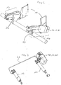
- FIG. 1 in which a conventional tail lift system is shown.
- Conventional tail lift systems are common known, so here the structure and function only be briefly explained.
- a typical tail lift system 10 is described, for example, in EP-A-0 808 747, to which in Reference is made to the general structure.
- the tail lift system 10 shown here acts it is one in which only one actuator device 16 provided for the lifting and lowering process is short, stroke actuator device 16 in the following called.
- the stroke actuator device 16 and the folding actuator device 17 through a variety of hydraulic lines 19 connected with each other, noting is that in Fig. 1 only one of the hydraulic lines 19 is shown symbolically and this with a valve block and with a hydraulic fluid tank are connected (not shown separately here).
- the hydraulic system is one pump or there are several Pumps integrated, which by means of an electric motor, if necessary also several electric motors, pump and electric motor are not shown here, are driven to the to generate the necessary operating pressure of the hydraulic fluid.
- the control device 18 attached to the vehicle is via electrical control lines with the hydraulic circuit via controls such as relays, switches and the like. connected in a manner known per se, so that the standard movements of the tail lift systems 15 like lifting and lowering vertically and folding from the vertical to the horizontal and back over the correspondingly loaded hydraulic and Folding actuators 16, 17 can be effected.
- the tail lift system according to the invention shown in FIG. 2 10 differs from the known tailgate system designed in a conventional manner 10 acc. Fig. 1 essentially in that the folding actuator device 17 a "single" of these assigned electric motor 160.
- the electric motor 160 is the one shown in FIG Loading tailgate system on the side of the folding actuator device 17 arranged. But it is also fundamental possible to use the electric motor 160 instead of directly on the Folding actuator device 17 on the stroke actuator device 16 to arrange.
- the electric motor 170 is over here a housing 21 integral with the folding actuator device 17 trained. In the housing 21 there is also a hydraulic device 20 arranged, such as in the form a hydraulic circuit acc. Fig. 4 is formed. On the function of the hydraulic circuit known per se gem. Fig. 4 is still below, so far for that Understanding of the invention required, still received become.
- At least the electric motor 160 is in the housing 16 arranged and the hydraulic unit 20, cf. Fig. 4. From the hydraulic unit 20, cf. especially also Fig. 3, the already mentioned hydraulic line 22 leads to Stroke actuator 16.
- the hydraulic unit 20 can Electric motor 170 also include integrally, as shown in Fig. 4 is shown.
- the hydraulic unit 20 arranged in the housing 21 4 dash-dotted border (large bordered Field) includes the electric motor 160, which is a pump 200 drives the hydraulic fluid 201 from a hydraulic tank 202 on a directional valve (two-way valve) 203 promotes. The hydraulic fluid 201 is then over the Directional control valve 203 to a directly the lifting cylinder 16, see. 3 left.
- the hydraulic medium 202 supplied from the directional control valve 203 is also supplied to the directional control valve 204, which is connected to the Folding actuator 17 is connected.
Landscapes
- Engineering & Computer Science (AREA)
- Mechanical Engineering (AREA)
- Transportation (AREA)
- Physics & Mathematics (AREA)
- Fluid Mechanics (AREA)
- General Engineering & Computer Science (AREA)
- Motorcycle And Bicycle Frame (AREA)
- Vehicle Body Suspensions (AREA)
- Forklifts And Lifting Vehicles (AREA)
- Fluid-Pressure Circuits (AREA)
- Body Structure For Vehicles (AREA)
- Loading Or Unloading Of Vehicles (AREA)
Priority Applications (3)
| Application Number | Priority Date | Filing Date | Title |
|---|---|---|---|
| AT03002474T ATE336399T1 (de) | 2003-02-05 | 2003-02-05 | Ladebordwandsystem mit wenigstens einem klappaktuator und einem hubaktuator |
| EP03002474A EP1445145B1 (fr) | 2003-02-05 | 2003-02-05 | Sytème de hayon élévateur avec au moins un actionneur pour pivotement et élévation |
| DE50304648T DE50304648D1 (de) | 2003-02-05 | 2003-02-05 | Ladebordwandsystem mit wenigstens einem Klappaktuator und einem Hubaktuator |
Applications Claiming Priority (1)
| Application Number | Priority Date | Filing Date | Title |
|---|---|---|---|
| EP03002474A EP1445145B1 (fr) | 2003-02-05 | 2003-02-05 | Sytème de hayon élévateur avec au moins un actionneur pour pivotement et élévation |
Publications (2)
| Publication Number | Publication Date |
|---|---|
| EP1445145A1 true EP1445145A1 (fr) | 2004-08-11 |
| EP1445145B1 EP1445145B1 (fr) | 2006-08-16 |
Family
ID=32605331
Family Applications (1)
| Application Number | Title | Priority Date | Filing Date |
|---|---|---|---|
| EP03002474A Expired - Lifetime EP1445145B1 (fr) | 2003-02-05 | 2003-02-05 | Sytème de hayon élévateur avec au moins un actionneur pour pivotement et élévation |
Country Status (3)
| Country | Link |
|---|---|
| EP (1) | EP1445145B1 (fr) |
| AT (1) | ATE336399T1 (fr) |
| DE (1) | DE50304648D1 (fr) |
Cited By (1)
| Publication number | Priority date | Publication date | Assignee | Title |
|---|---|---|---|---|
| WO2006133964A3 (fr) * | 2005-06-16 | 2007-04-19 | Maier Gmbh Peter | Paroi d'un bord de chargement |
Citations (4)
| Publication number | Priority date | Publication date | Assignee | Title |
|---|---|---|---|---|
| US5255517A (en) * | 1989-09-13 | 1993-10-26 | Weber Guenter | Control device for hydraulic operating cylinders of a combined lifting platform and a closing wall of a vehicle |
| EP0832783A1 (fr) * | 1996-09-25 | 1998-04-01 | Pabco, Co., Ltd. | Commande et procédé d'une installation de levage |
| DE19756310A1 (de) * | 1997-12-12 | 1999-06-17 | Soerensen Hydraulik Gmbh | Ladebordwandsystem mit Überlastschutz |
| EP1010575A1 (fr) * | 1998-12-17 | 2000-06-21 | Sörensen Hydraulik Zweigniederlassung, Ulfborg, Filial af Sörensen Hydraulik GmbH, Tyskland | Système de hayon élévateur avec au moins un actionneur |
-
2003
- 2003-02-05 DE DE50304648T patent/DE50304648D1/de not_active Expired - Lifetime
- 2003-02-05 EP EP03002474A patent/EP1445145B1/fr not_active Expired - Lifetime
- 2003-02-05 AT AT03002474T patent/ATE336399T1/de not_active IP Right Cessation
Patent Citations (4)
| Publication number | Priority date | Publication date | Assignee | Title |
|---|---|---|---|---|
| US5255517A (en) * | 1989-09-13 | 1993-10-26 | Weber Guenter | Control device for hydraulic operating cylinders of a combined lifting platform and a closing wall of a vehicle |
| EP0832783A1 (fr) * | 1996-09-25 | 1998-04-01 | Pabco, Co., Ltd. | Commande et procédé d'une installation de levage |
| DE19756310A1 (de) * | 1997-12-12 | 1999-06-17 | Soerensen Hydraulik Gmbh | Ladebordwandsystem mit Überlastschutz |
| EP1010575A1 (fr) * | 1998-12-17 | 2000-06-21 | Sörensen Hydraulik Zweigniederlassung, Ulfborg, Filial af Sörensen Hydraulik GmbH, Tyskland | Système de hayon élévateur avec au moins un actionneur |
Cited By (2)
| Publication number | Priority date | Publication date | Assignee | Title |
|---|---|---|---|---|
| WO2006133964A3 (fr) * | 2005-06-16 | 2007-04-19 | Maier Gmbh Peter | Paroi d'un bord de chargement |
| EP2196356A1 (fr) * | 2005-06-16 | 2010-06-16 | Peter Maier Leichtbau GmbH | Hayon élévateur |
Also Published As
| Publication number | Publication date |
|---|---|
| DE50304648D1 (de) | 2006-09-28 |
| ATE336399T1 (de) | 2006-09-15 |
| EP1445145B1 (fr) | 2006-08-16 |
Similar Documents
| Publication | Publication Date | Title |
|---|---|---|
| DE2840045C2 (fr) | ||
| EP0453752B1 (fr) | Autobus, en particulier à plate-forme surbaissée | |
| AT399130B (de) | Anordnung zur hydraulischen betätigung eines fahrzeugverdeckes | |
| EP1900676B1 (fr) | Elévateur de charges | |
| DE102007030107B4 (de) | Verfahren und System zum elektrohydraulischen Ausrichten von Tragkörpern | |
| DE2116842A1 (de) | Fahrbarer, zum Aufbau auf Kraftfahrzeuge bestimmter Kran mit drei hydraulisch gesteuerten Hebestufen | |
| EP1752587A1 (fr) | Agencement hydraulique | |
| EP2878571A1 (fr) | Dispositif de levage destiné à soulever de lourdes charges | |
| EP3027476B1 (fr) | Véhicule terrestre avec une pluralité d'unités de support de coin de véhicule | |
| DE102008049135A1 (de) | Hydrauliksystem zum Verstellen von Flügel-Aufbauteilen eines Lkws | |
| EP1445145B1 (fr) | Sytème de hayon élévateur avec au moins un actionneur pour pivotement et élévation | |
| EP1010575B1 (fr) | Système de hayon élévateur avec au moins un actionneur pour levage | |
| DE102021105025A1 (de) | Schwenkantrieb für Durchladezug | |
| EP4001027A1 (fr) | Système hydraulique pour un véhicule ou un conteneur, véhicule ou conteneur doté d'un tel système hydraulique | |
| DE19637907C2 (de) | Elektrohydraulische Dachliftanlage | |
| DE69302766T2 (de) | Zentrale Steuereinrichtung für betätigbare Aufstellstützen eines Brandschutzfahrzeuges mit Drehleiter oder dergleichen | |
| DE19938071B4 (de) | Schienenfahrzeug | |
| DE20309190U1 (de) | Elektrohydraulische Steuervorrichtung und Hebezeug | |
| EP1118500A1 (fr) | Système de hayon élévateur | |
| DE102020120562A1 (de) | Fahrzeuganhänger und Zuggespann mit einem solchen Fahrzeuganhänger | |
| DE102013222299B4 (de) | Verfahren zum Betreiben einer Hubladebühne | |
| EP1607366B1 (fr) | Véhicule élévateur avec un dispositif de levage de type mécanisme à ciseaux | |
| EP3623214B1 (fr) | Véhicule utilitaire pourvu de plancher de chargement pouvant être abaissé | |
| AT405752B (de) | Anordnung zur hydraulischen betätigung eines heckdeckels | |
| DE102007015820A1 (de) | Hydraulisch betätigte Ladebordwand |
Legal Events
| Date | Code | Title | Description |
|---|---|---|---|
| PUAI | Public reference made under article 153(3) epc to a published international application that has entered the european phase |
Free format text: ORIGINAL CODE: 0009012 |
|
| 17P | Request for examination filed |
Effective date: 20030305 |
|
| AK | Designated contracting states |
Kind code of ref document: A1 Designated state(s): AT BE BG CH CY CZ DE DK EE ES FI FR GB GR HU IE IT LI LU MC NL PT SE SI SK TR |
|
| AX | Request for extension of the european patent |
Extension state: AL LT LV MK RO |
|
| 17Q | First examination report despatched |
Effective date: 20050127 |
|
| AKX | Designation fees paid |
Designated state(s): AT BE BG CH CY CZ DE DK EE ES FI FR GB GR HU IE IT LI LU MC NL PT SE SI SK TR |
|
| AXX | Extension fees paid |
Extension state: LT Payment date: 20030305 Extension state: RO Payment date: 20030305 Extension state: MK Payment date: 20030305 Extension state: AL Payment date: 20030305 Extension state: LV Payment date: 20030305 |
|
| GRAP | Despatch of communication of intention to grant a patent |
Free format text: ORIGINAL CODE: EPIDOSNIGR1 |
|
| GRAS | Grant fee paid |
Free format text: ORIGINAL CODE: EPIDOSNIGR3 |
|
| GRAA | (expected) grant |
Free format text: ORIGINAL CODE: 0009210 |
|
| AK | Designated contracting states |
Kind code of ref document: B1 Designated state(s): AT BE BG CH CY CZ DE DK EE ES FI FR GB GR HU IE IT LI LU MC NL PT SE SI SK TR |
|
| AX | Request for extension of the european patent |
Extension state: AL LT LV MK RO |
|
| PG25 | Lapsed in a contracting state [announced via postgrant information from national office to epo] |
Ref country code: IT Free format text: LAPSE BECAUSE OF FAILURE TO SUBMIT A TRANSLATION OF THE DESCRIPTION OR TO PAY THE FEE WITHIN THE PRESCRIBED TIME-LIMIT;WARNING: LAPSES OF ITALIAN PATENTS WITH EFFECTIVE DATE BEFORE 2007 MAY HAVE OCCURRED AT ANY TIME BEFORE 2007. THE CORRECT EFFECTIVE DATE MAY BE DIFFERENT FROM THE ONE RECORDED. Effective date: 20060816 Ref country code: NL Free format text: LAPSE BECAUSE OF FAILURE TO SUBMIT A TRANSLATION OF THE DESCRIPTION OR TO PAY THE FEE WITHIN THE PRESCRIBED TIME-LIMIT Effective date: 20060816 Ref country code: IE Free format text: LAPSE BECAUSE OF FAILURE TO SUBMIT A TRANSLATION OF THE DESCRIPTION OR TO PAY THE FEE WITHIN THE PRESCRIBED TIME-LIMIT Effective date: 20060816 Ref country code: CZ Free format text: LAPSE BECAUSE OF FAILURE TO SUBMIT A TRANSLATION OF THE DESCRIPTION OR TO PAY THE FEE WITHIN THE PRESCRIBED TIME-LIMIT Effective date: 20060816 Ref country code: SI Free format text: LAPSE BECAUSE OF FAILURE TO SUBMIT A TRANSLATION OF THE DESCRIPTION OR TO PAY THE FEE WITHIN THE PRESCRIBED TIME-LIMIT Effective date: 20060816 Ref country code: SK Free format text: LAPSE BECAUSE OF FAILURE TO SUBMIT A TRANSLATION OF THE DESCRIPTION OR TO PAY THE FEE WITHIN THE PRESCRIBED TIME-LIMIT Effective date: 20060816 Ref country code: FI Free format text: LAPSE BECAUSE OF FAILURE TO SUBMIT A TRANSLATION OF THE DESCRIPTION OR TO PAY THE FEE WITHIN THE PRESCRIBED TIME-LIMIT Effective date: 20060816 |
|
| REG | Reference to a national code |
Ref country code: GB Ref legal event code: FG4D Free format text: NOT ENGLISH |
|
| GBT | Gb: translation of ep patent filed (gb section 77(6)(a)/1977) |
Effective date: 20060816 |
|
| REG | Reference to a national code |
Ref country code: CH Ref legal event code: EP |
|
| REG | Reference to a national code |
Ref country code: IE Ref legal event code: FG4D Free format text: LANGUAGE OF EP DOCUMENT: GERMAN |
|
| REF | Corresponds to: |
Ref document number: 50304648 Country of ref document: DE Date of ref document: 20060928 Kind code of ref document: P |
|
| PG25 | Lapsed in a contracting state [announced via postgrant information from national office to epo] |
Ref country code: BG Free format text: LAPSE BECAUSE OF FAILURE TO SUBMIT A TRANSLATION OF THE DESCRIPTION OR TO PAY THE FEE WITHIN THE PRESCRIBED TIME-LIMIT Effective date: 20061116 Ref country code: DK Free format text: LAPSE BECAUSE OF FAILURE TO SUBMIT A TRANSLATION OF THE DESCRIPTION OR TO PAY THE FEE WITHIN THE PRESCRIBED TIME-LIMIT Effective date: 20061116 Ref country code: SE Free format text: LAPSE BECAUSE OF FAILURE TO SUBMIT A TRANSLATION OF THE DESCRIPTION OR TO PAY THE FEE WITHIN THE PRESCRIBED TIME-LIMIT Effective date: 20061116 |
|
| PG25 | Lapsed in a contracting state [announced via postgrant information from national office to epo] |
Ref country code: ES Free format text: LAPSE BECAUSE OF FAILURE TO SUBMIT A TRANSLATION OF THE DESCRIPTION OR TO PAY THE FEE WITHIN THE PRESCRIBED TIME-LIMIT Effective date: 20061127 |
|
| PG25 | Lapsed in a contracting state [announced via postgrant information from national office to epo] |
Ref country code: PT Free format text: LAPSE BECAUSE OF FAILURE TO SUBMIT A TRANSLATION OF THE DESCRIPTION OR TO PAY THE FEE WITHIN THE PRESCRIBED TIME-LIMIT Effective date: 20070116 |
|
| LTIE | Lt: invalidation of european patent or patent extension |
Effective date: 20060816 |
|
| NLV1 | Nl: lapsed or annulled due to failure to fulfill the requirements of art. 29p and 29m of the patents act | ||
| PG25 | Lapsed in a contracting state [announced via postgrant information from national office to epo] |
Ref country code: CH Free format text: LAPSE BECAUSE OF NON-PAYMENT OF DUE FEES Effective date: 20070228 Ref country code: LI Free format text: LAPSE BECAUSE OF NON-PAYMENT OF DUE FEES Effective date: 20070228 Ref country code: MC Free format text: LAPSE BECAUSE OF NON-PAYMENT OF DUE FEES Effective date: 20070228 |
|
| REG | Reference to a national code |
Ref country code: IE Ref legal event code: FD4D |
|
| ET | Fr: translation filed | ||
| PLBE | No opposition filed within time limit |
Free format text: ORIGINAL CODE: 0009261 |
|
| STAA | Information on the status of an ep patent application or granted ep patent |
Free format text: STATUS: NO OPPOSITION FILED WITHIN TIME LIMIT |
|
| 26N | No opposition filed |
Effective date: 20070518 |
|
| REG | Reference to a national code |
Ref country code: CH Ref legal event code: PL |
|
| BERE | Be: lapsed |
Owner name: SORENSEN HYDRAULIK, ZWEIGNIEDERLASSUNG, ULFBORG, Effective date: 20070228 |
|
| PG25 | Lapsed in a contracting state [announced via postgrant information from national office to epo] |
Ref country code: BE Free format text: LAPSE BECAUSE OF NON-PAYMENT OF DUE FEES Effective date: 20070228 |
|
| PG25 | Lapsed in a contracting state [announced via postgrant information from national office to epo] |
Ref country code: GR Free format text: LAPSE BECAUSE OF FAILURE TO SUBMIT A TRANSLATION OF THE DESCRIPTION OR TO PAY THE FEE WITHIN THE PRESCRIBED TIME-LIMIT Effective date: 20061117 |
|
| PG25 | Lapsed in a contracting state [announced via postgrant information from national office to epo] |
Ref country code: AT Free format text: LAPSE BECAUSE OF NON-PAYMENT OF DUE FEES Effective date: 20070205 |
|
| PG25 | Lapsed in a contracting state [announced via postgrant information from national office to epo] |
Ref country code: EE Free format text: LAPSE BECAUSE OF FAILURE TO SUBMIT A TRANSLATION OF THE DESCRIPTION OR TO PAY THE FEE WITHIN THE PRESCRIBED TIME-LIMIT Effective date: 20060816 |
|
| PGFP | Annual fee paid to national office [announced via postgrant information from national office to epo] |
Ref country code: GB Payment date: 20090223 Year of fee payment: 7 |
|
| PG25 | Lapsed in a contracting state [announced via postgrant information from national office to epo] |
Ref country code: CY Free format text: LAPSE BECAUSE OF FAILURE TO SUBMIT A TRANSLATION OF THE DESCRIPTION OR TO PAY THE FEE WITHIN THE PRESCRIBED TIME-LIMIT Effective date: 20060816 Ref country code: LU Free format text: LAPSE BECAUSE OF NON-PAYMENT OF DUE FEES Effective date: 20070205 |
|
| PG25 | Lapsed in a contracting state [announced via postgrant information from national office to epo] |
Ref country code: HU Free format text: LAPSE BECAUSE OF FAILURE TO SUBMIT A TRANSLATION OF THE DESCRIPTION OR TO PAY THE FEE WITHIN THE PRESCRIBED TIME-LIMIT Effective date: 20070217 Ref country code: TR Free format text: LAPSE BECAUSE OF FAILURE TO SUBMIT A TRANSLATION OF THE DESCRIPTION OR TO PAY THE FEE WITHIN THE PRESCRIBED TIME-LIMIT Effective date: 20060816 |
|
| PGFP | Annual fee paid to national office [announced via postgrant information from national office to epo] |
Ref country code: FR Payment date: 20090220 Year of fee payment: 7 |
|
| PGFP | Annual fee paid to national office [announced via postgrant information from national office to epo] |
Ref country code: DE Payment date: 20100428 Year of fee payment: 8 |
|
| GBPC | Gb: european patent ceased through non-payment of renewal fee |
Effective date: 20100205 |
|
| REG | Reference to a national code |
Ref country code: FR Ref legal event code: ST Effective date: 20101029 |
|
| PG25 | Lapsed in a contracting state [announced via postgrant information from national office to epo] |
Ref country code: FR Free format text: LAPSE BECAUSE OF NON-PAYMENT OF DUE FEES Effective date: 20100301 |
|
| PG25 | Lapsed in a contracting state [announced via postgrant information from national office to epo] |
Ref country code: GB Free format text: LAPSE BECAUSE OF NON-PAYMENT OF DUE FEES Effective date: 20100205 |
|
| REG | Reference to a national code |
Ref country code: DE Ref legal event code: R119 Ref document number: 50304648 Country of ref document: DE Effective date: 20110901 |
|
| PG25 | Lapsed in a contracting state [announced via postgrant information from national office to epo] |
Ref country code: DE Free format text: LAPSE BECAUSE OF NON-PAYMENT OF DUE FEES Effective date: 20110901 |