EP1445153A2 - Fahrzeug mit einem einziehbaren Unterfahrschutzbalken - Google Patents
Fahrzeug mit einem einziehbaren Unterfahrschutzbalken Download PDFInfo
- Publication number
- EP1445153A2 EP1445153A2 EP04290281A EP04290281A EP1445153A2 EP 1445153 A2 EP1445153 A2 EP 1445153A2 EP 04290281 A EP04290281 A EP 04290281A EP 04290281 A EP04290281 A EP 04290281A EP 1445153 A2 EP1445153 A2 EP 1445153A2
- Authority
- EP
- European Patent Office
- Prior art keywords
- bar
- underrun
- sections
- underrun bar
- articulated
- Prior art date
- Legal status (The legal status is an assumption and is not a legal conclusion. Google has not performed a legal analysis and makes no representation as to the accuracy of the status listed.)
- Granted
Links
Images


Classifications
-
- B—PERFORMING OPERATIONS; TRANSPORTING
- B60—VEHICLES IN GENERAL
- B60R—VEHICLES, VEHICLE FITTINGS, OR VEHICLE PARTS, NOT OTHERWISE PROVIDED FOR
- B60R19/00—Wheel guards; Radiator guards, e.g. grilles; Obstruction removers; Fittings damping bouncing force in collisions
- B60R19/56—Fittings damping bouncing force in truck collisions, e.g. bumpers; Arrangements on high-riding vehicles, e.g. lorries, for preventing vehicles or objects from running thereunder
-
- B—PERFORMING OPERATIONS; TRANSPORTING
- B60—VEHICLES IN GENERAL
- B60R—VEHICLES, VEHICLE FITTINGS, OR VEHICLE PARTS, NOT OTHERWISE PROVIDED FOR
- B60R19/00—Wheel guards; Radiator guards, e.g. grilles; Obstruction removers; Fittings damping bouncing force in collisions
- B60R19/02—Bumpers, i.e. impact receiving or absorbing members for protecting vehicles or fending off blows from other vehicles or objects
- B60R19/24—Arrangements for mounting bumpers on vehicles
- B60R19/38—Arrangements for mounting bumpers on vehicles adjustably or movably mounted, e.g. horizontally displaceable for securing a space between parked vehicles
-
- B—PERFORMING OPERATIONS; TRANSPORTING
- B60—VEHICLES IN GENERAL
- B60R—VEHICLES, VEHICLE FITTINGS, OR VEHICLE PARTS, NOT OTHERWISE PROVIDED FOR
- B60R21/00—Arrangements or fittings on vehicles for protecting or preventing injuries to occupants or pedestrians in case of accidents or other traffic risks
- B60R2021/0002—Type of accident
- B60R2021/0011—Rear collision or recoiling bounce after frontal collision
Definitions
- the invention generally relates to vehicles automobiles fitted with underrun bars.
- the invention relates to a vehicle automobile comprising two substantially rear spars longitudinal, a transverse underrun bar linked to the two beams and movable relative to stringers between a lower position relatively more low and a relatively higher upper position, and connecting means between the underrun bar and the side members.
- Vehicles of this type are known in the art anterior, and typically include mounted bars swivel on the side members by means of arms rigid. The bar moves from its lower position to its upper position by rotating towards back and up around an axis of rotation transverse, as shown in Figure 1.
- the bar in its upper position, is then troublesome, for example to unload the vehicle by the rear, or, when the vehicle is a dump truck, to empty the skip.
- the object of the present invention is to remedy the above-mentioned defect.
- the device of the invention by elsewhere conforms to the generic definition given by it the preamble above, is essentially characterized in that the displacement of the underrun bar between its upper and lower positions corresponds to a translational movement in a reference plane.
- the underrun bar is close to stringers passing from the lower position to its upper position.
- the connecting means between the underrun bar and side rails include right and left arms, these arms each comprising mutually articulated front and rear sections, the front section also being articulated to a spar and the rear section also being articulated to the bar underride.
- the front and rear sections form an open angle to each other in the lower position of the underrun bar, and a closed angle to each other in the upper position of the underrun bar.
- the front sections are articulated on the side members by front axes perpendicular to the plane reference, the front and rear sections being mutually articulated by intermediate axes perpendicular to the reference plane, and the sections rear being articulated on the underrun bar by rear axes perpendicular to the plane of reference.
- the intermediate axes are move laterally out of the vehicle when the underrun bar moves from its position lower than its upper position.
- the means of connection between the bar underrun and the side members include means locking the front sections in the positions that these sections occupy in the lower positions and upper of the underrun bar.
- the means of connection between the bar underrun and side rails include members which stress the rear sections in rotation around the rear axes outwards.
- the bodies requesting the sections rear rotating are two gas cylinders each articulated by a first end to one of the axes intermediaries, and by a second end opposite the first to the underrun bar, the gas cylinders stressing the intermediate axis and the bar in the direction of a mutual spacing, the second end of the cylinder each arm being shifted towards the middle of the bar relative to the corresponding rear axle.
- the front sections are U-profiles with grooves open towards the median longitudinal plane of the vehicle and in which the rear sections are housed in position upper of the underrun bar.
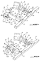
- the motor vehicle partially represented on Figure 2 includes two parallel rear spars 1 and longitudinal, an underrun bar 10 transverse linked to two spars 1 and mobile relative to the side members 1 between a position relatively lower lower and a position higher relatively higher, and means of connection between the underrun bar 10 and the stringers 1.
- the side members 1 are arranged on both sides opposite sides of the vehicle, symmetrically with respect to in the median longitudinal plane of this vehicle.
- This type of bar is generally installed on industrial vehicles fitted with large diameter wheels and whose body is located at a significant height by ground level relative to a passenger car.
- the underrun bar is a system of safety to prevent the front parts of the passenger cars, in the event of a rear impact industrial vehicles, come under the body, and that the upper part of the vehicle impacts then directly the case.
- the underrun bar 10 In its lower position, the underrun bar 10 is located at an intermediate level between the body and the ground and prohibited cars from tourism to fit under the body.
- the displacement of the underrun bar 10 between its upper positions and lower corresponds to a translational movement in a reference plane P.
- the underrun bar 10 is linked to parts of ends respective rear 2 of the side members 1. It is located, in its lower position, significantly lower and significantly more at the back than the parts rear ends 2. In its upper position, it is immediately below and immediately behind the rear end parts 2. The bar 10 therefore approaches the side members 1 passing from the position lower than its upper position.
- the reference plane P is a transverse plane slightly inclined with respect to the horizontal.
- the connecting means between the underrun bar 10 and the side members 1 include 20 right and left arms, these arms each comprising front 30 and rear 40 sections mutually articulated, the front section 30 being hinged to the rear end part 2 of a spar 1 and the rear section 40 being articulated to the bar underrun 10.
- These arms 20 are movable between a configuration deployed in which the front and rear sections 30 and 40 form an open angle with respect to each other, and a folded configuration in which they form a angle closed relative to each other.
- front and rear sections 30 and 40 in the deployed configuration, are aligned in the extension of each other and extend in a longitudinal vertical plane, and, in the configuration folded, the front and rear sections 30 and 40 are arranged along one another and extend in a transverse direction.
- the deployed configuration of the arms 20 corresponds to the lower position of the underrun bar 10, and the configuration folded to the upper position.
- the front 30 and rear 40 sections are U-shaped, including front and rear backs respective 35 and 45 and raised edges front and rear respectively 36 and 46 standing on the two opposite sides of the matching back.
- the back and the edges define front and rear grooves 31 and 41 open towards the plane median longitudinal of the vehicle in the deployed configuration arms 20.
- the front sections 30 each have a front articulation end 32 articulated on the spar 1 corresponding by a front axis 34 extending perpendicular to the reference plane P.
- Each front section 30 also has a front intermediate end 33 opposite the end front articulation 32 articulated by an axis intermediate 50 at a rear intermediate end 43 of the rear section 40.
- the intermediate axis 50 extends perpendicular to the reference plane P.
- each rear section 40 has a rear articulation end 42 opposite the end rear intermediate 43 and articulated on the underrun bar 10 by a rear axle 44 extending perpendicular to the reference plane.
- intermediate axes 50 of two arms 20 move laterally outward away from each other, when the underrun bar 10 moves from position lower than its upper position.
- the front sections 30 are linked to the side members 1 by by means of plates 70 rigidly fixed on external lateral faces 3 of the side members 1.
- These plates 70 are longitudinal vertical plates and are drilled with holes 71 through which they are screwed on the side members 1. They can also be fixed by other means such as welding.
- a reinforcing plate 72 extends from an edge front opposite the underrun bar 10 of each plates 70. These plates came from material or welded onto plates 70 and extend laterally towards the outside of the vehicle, perpendicular to the turntables 70.
- Two support plates 73 are each rigidly fixed by two edges mutually perpendicular to one of the plates 70 and the reinforcement plate 72 corresponding. These support plates 73 extend in the reference plane P and are fixed by means known to plate 70 and plate 72, for example by welding.
- This gusset has the shape of a right triangle and is rigidly fixed by its hypothenuse on the support plate 73 and by a small side on the reinforcement plate 72.
- the front articulation end 32 of the section before 30 rests on the support plate 73 by one of its erect edges 36.
- the two erect edges 36 of the front articulation end 32 are crossed by two respective front cylindrical drums 37 aligned with each other, and integral with the erect edges 36.
- a massive guide piece 75 is rigidly fixed to the plate 70 and engaged in the front groove 31 at the articulation end before 32.
- This part has a cylindrical orifice, and just fits between the two barrels cylindrical front 37, so that the orifice of the massive piece and the front barrels are perfectly aligned and form a continuous cylindrical conduit in which the front axle 34 is engaged.
- the barrels before 37 have ends projecting from the erect edges 36 above and below the front section 34, the end protruding below being engaged in an orifice of the support plate 73 corresponding and flush with a face of the support plate 73 opposite the front section 30.
- the front axle 34 consists of a screw having an enlarged front head 341 and a threaded end 342 opposite head 341.
- the head 341 is in support on the face of the support plate 73 opposite the front section 30, the front axis 34 crossing successively the support plate 73, a barrel before 37, the massive piece 75, the second barrel before 37, and the threaded end 342 protruding above this last barrel before 37.
- a 343 nut is screwed onto the threaded end 342 and comes to carry by via a 344 washer on the barrel.
- the front axle 34 is free to rotate relative to massive piece 75.
- the rear section 40 is formed of a profile of width less than the width of the front section 30, the width understood as the distance between the edges prepared.
- the rear intermediate end 43 is engaged in the front groove 31, at the intermediate end before 33.
- the two erect edges 36 of the end intermediate before 33 are crossed by two barrels cylindrical intermediate 38 respective aligned one with the other, and integral with the erect edges 36.
- the intermediate axis 50 is also made up a screw with an enlarged intermediate head 501 and an intermediate threaded end 502 opposite the head 501.
- the head 501 is supported on a lower face of the raised edge 36 opposite the rear section 40, the intermediate axis 50 successively crossing the two intermediate barrels 38, and the threaded end 502 projecting above of the latter was intermediate 38.
- a nut intermediate 503 is screwed onto the threaded end 502 and comes to carry via a washer intermediate 504 on the barrel.
- intermediate end rear 43 The erect edges of the intermediate end rear 43 are crossed by intermediate barrels 38 and free to rotate relative to these barrels.
- the two rear articulation ends 42 are each articulated on a yoke 11 rigidly fixed on the underrun bar 10 by known means, for example example by welding.
- Clevis 11 includes two plates 111 fixed on upper and lower faces opposite of the bar 10 and comprising parts making protrusion towards the rear section 40 relative to the closed off. These two parts extend opposite one of the other, and the rear hinge end 42 is engaged between them.
- the rear axle 44 is in practice composed of two screws 441 aligned, each one crossing a raised edge 46 of the rear hinge end and one of the plates 111.
- the raised edge and the plate are caught between a head 442 of the screw 441 and a nut 443 screwed on the end of the screw opposite the head.
- the means of connection between the underrun bar 10 and the side members 1 include members requesting the rear sections 40 in rotation around the rear axes 44 outwards.
- These organs are two gas cylinders 60, one on each arm 20, each being articulated by a first end 61 to one of the intermediate axes 50, and to a second end 62 opposite the first at the helm underrun 10.
- the first end 61 is shaped as a ring and is crossed by the intermediate axis 50. It is disposed between the two intermediate barrels 38 and is free to rotate both relative to the axis intermediate 50 and intermediate barrels 38.
- the second end 62 is articulated in a other yoke 63 secured to a front face 12 of the bar underrun 10 facing the rear section 40.
- This other yoke 63 includes an axis of articulation of the second end 62 extending perpendicular to the reference plane P, so that the cylinder can debate in plan P.
- each arm is slightly offset towards the middle of the bar 10 relative to the corresponding rear axle 44.
- the gas cylinders 60 extend parallel to the rear section 40 in the deployed configuration of the arms 20, the other yoke 63 then being located exactly in the arm extension.
- the cylinder is then in the state compressed and stresses the intermediate axis 50 and the bar 10 in the direction of mutual spacing. It thus creates a torque around the rear axis 44 which tends to move the intermediate axis 50 outwards.
- the means of connection between the underrun bar 10 and the side members 1 include means for locking the front sections 30 in the positions that these sections occupy in the positions lower and upper of the underrun bar 10.
- These locking means comprise for each arm 20 a pivoting plate 81 secured to the section before 30 and moving on the support plate 30 when the front section 30 pivots around the front axis 34, and a handle 80 mounted on the pivoting plate 81.
- the handle 80 can selectively adopt a locking position in which a rod 84, shown in figure 9, protrudes under the plate pivoting, and a release position in which the rod 84 is retracted inside the handle and does not does not protrude under the swivel plate 81.
- the support plate 73 is pierced with two holes of lock 82 at selected locations so that the rod 84 of the handle comes to engage in these holes when the handle 80 is in the locked position and when the front section 30 is respectively in positions corresponding to the lower positions and top of underrun bar 10.
- the front section 30 is thus locked in position. Note that the rear section 40 remains free relative to the front section 30.
- angle of inclination of the plane of reference P relative to the horizontal is chosen at case by case depending on the type and size of the vehicle.
Landscapes
- Engineering & Computer Science (AREA)
- Mechanical Engineering (AREA)
- Body Structure For Vehicles (AREA)
- Vehicle Body Suspensions (AREA)
- Automatic Cycles, And Cycles In General (AREA)
- Lighting Device Outwards From Vehicle And Optical Signal (AREA)
- Vehicle Step Arrangements And Article Storage (AREA)
- Steering Devices For Bicycles And Motorcycles (AREA)
Applications Claiming Priority (2)
| Application Number | Priority Date | Filing Date | Title |
|---|---|---|---|
| FR0301299 | 2003-02-04 | ||
| FR0301299A FR2850618B1 (fr) | 2003-02-04 | 2003-02-04 | Vehicule equipe d'une barre anti-encastrement retractable |
Publications (3)
| Publication Number | Publication Date |
|---|---|
| EP1445153A2 true EP1445153A2 (de) | 2004-08-11 |
| EP1445153A3 EP1445153A3 (de) | 2005-03-23 |
| EP1445153B1 EP1445153B1 (de) | 2006-04-26 |
Family
ID=32606000
Family Applications (1)
| Application Number | Title | Priority Date | Filing Date |
|---|---|---|---|
| EP04290281A Expired - Lifetime EP1445153B1 (de) | 2003-02-04 | 2004-02-03 | Fahrzeug mit einem einziehbaren Unterfahrschutzbalken |
Country Status (5)
| Country | Link |
|---|---|
| EP (1) | EP1445153B1 (de) |
| AT (1) | ATE324298T1 (de) |
| DE (1) | DE602004000697T2 (de) |
| ES (1) | ES2263115T3 (de) |
| FR (1) | FR2850618B1 (de) |
Cited By (2)
| Publication number | Priority date | Publication date | Assignee | Title |
|---|---|---|---|---|
| EP1741602A3 (de) * | 2005-07-04 | 2008-02-27 | Franz Xaver Meiller Fahrzeug- und Maschinenfabrik-GmbH & Co KG | Unterfahrschutzeinrichtung für ein Lastentransportfahrzeug |
| CN115583214A (zh) * | 2022-08-31 | 2023-01-10 | 三一汽车起重机械有限公司 | 一种车辆后防护装置及车辆 |
Families Citing this family (1)
| Publication number | Priority date | Publication date | Assignee | Title |
|---|---|---|---|---|
| FR3125768B1 (fr) * | 2021-07-28 | 2025-12-05 | Marrel Sa | Dispositif anti-encastrement et véhicule pourvu d’un tel dispositif anti-encastrement |
Family Cites Families (5)
| Publication number | Priority date | Publication date | Assignee | Title |
|---|---|---|---|---|
| DE7510537U (de) * | 1975-04-04 | 1975-08-21 | Blumhardt C | Unterfahrschutzanordnung an Lastkraftwagen mit abkippbarer Ladefläche |
| FR2035181A5 (de) * | 1969-04-04 | 1970-12-18 | Gallien Pierre | |
| US3608943A (en) * | 1969-06-02 | 1971-09-28 | Frank T Gostomski | Extensible automobile bumper |
| DE9307389U1 (de) * | 1993-05-14 | 1993-07-29 | F.X. Meiller Fahrzeug- und Maschinenfabrik GmbH & Co KG, 80997 München | Vorrichtung zur Verhinderung des Unterfahrens eines Fahrzeuges von hinten |
| DE9419691U1 (de) * | 1993-12-13 | 1995-04-06 | Anton Ellinghaus Maschinenfabrik Und Apparatebauanstalt Gmbh & Co Kg, 59269 Beckum | Aufprallschutz für Fahrzeuge |
-
2003
- 2003-02-04 FR FR0301299A patent/FR2850618B1/fr not_active Expired - Lifetime
-
2004
- 2004-02-03 AT AT04290281T patent/ATE324298T1/de not_active IP Right Cessation
- 2004-02-03 DE DE602004000697T patent/DE602004000697T2/de not_active Expired - Lifetime
- 2004-02-03 EP EP04290281A patent/EP1445153B1/de not_active Expired - Lifetime
- 2004-02-03 ES ES04290281T patent/ES2263115T3/es not_active Expired - Lifetime
Cited By (2)
| Publication number | Priority date | Publication date | Assignee | Title |
|---|---|---|---|---|
| EP1741602A3 (de) * | 2005-07-04 | 2008-02-27 | Franz Xaver Meiller Fahrzeug- und Maschinenfabrik-GmbH & Co KG | Unterfahrschutzeinrichtung für ein Lastentransportfahrzeug |
| CN115583214A (zh) * | 2022-08-31 | 2023-01-10 | 三一汽车起重机械有限公司 | 一种车辆后防护装置及车辆 |
Also Published As
| Publication number | Publication date |
|---|---|
| FR2850618A1 (fr) | 2004-08-06 |
| DE602004000697T2 (de) | 2007-04-26 |
| FR2850618B1 (fr) | 2006-09-15 |
| ES2263115T3 (es) | 2006-12-01 |
| ATE324298T1 (de) | 2006-05-15 |
| EP1445153A3 (de) | 2005-03-23 |
| EP1445153B1 (de) | 2006-04-26 |
| DE602004000697D1 (de) | 2006-06-01 |
Similar Documents
| Publication | Publication Date | Title |
|---|---|---|
| EP3691959B1 (de) | Koppelbares automotives strassenfahrzeug mit kompakter lenkung und aufhängung | |
| FR2735430A1 (fr) | Benne et vehicule la comportant | |
| FR2774350A1 (fr) | Structure de chassis pour un engin de travaux publics | |
| FR2655007A1 (fr) | Ensemble d'attelage d'un vehicule tracteur et d'une remorque. | |
| EP3650322B1 (de) | Karosserie eines strassenfahrzeugs für den warentransport, die rückspoiler umfasst | |
| EP1445153B1 (de) | Fahrzeug mit einem einziehbaren Unterfahrschutzbalken | |
| EP1243464A1 (de) | Ladevorrichtung und ein mit solch einer Ladevorrichtung ausgerüstetes Fahrzeug | |
| EP2505429B1 (de) | Verfahren zur Regulierung des Achsabstands einer rollenden Einheit, die mindestens zwei Fördervorrichtungen für Container umfasst | |
| FR2690883A1 (fr) | Mécanisme d'actionnement pour le bras arrière basculant de levage/tractage d'un véhicule de dépannage. | |
| EP2110277A1 (de) | Kraftfahrzeug mit vier Rädern | |
| FR3058374A1 (fr) | Dispositif anti-encastrement retractable pour vehicule routier. | |
| FR2927285A1 (fr) | Dispositif de manutention pour le chargement et le dechargement d'un conteneur. | |
| FR2860460A1 (fr) | Siege escamotable de vehicule automobile, notamment arriere | |
| EP2199149B1 (de) | Abnehmbarer Aufbau zum Transport von Lasten | |
| EP1120333B1 (de) | Aufliegeranhänger mit faltbarem Schwanenhals | |
| FR3125261A1 (fr) | Dispositif arriere de protection anti-encastrement a barre escamotable et vehicule equipe d’un tel dispositif | |
| FR3037309A1 (fr) | Remorque semi articulee destinee a etre attelee a un vehicule tracteur et ensemble attele comprenant une telle remorque | |
| FR3074132A1 (fr) | Dispositif de ridelle d'un conteneur d'un vehicule de transport de charge | |
| EP1428719A2 (de) | Kraftfahrzeug mit einem einen flachen Boden aufweisendem Klappsitz | |
| EP2990263B1 (de) | Strassentransportfahrzeug mit einer haltestruktur zum beladen mit automatischem ein- und ausklinksystem | |
| FR3037308A1 (fr) | Remorque destinee a etre attelee a un vehicule tracteur et ensemble attele comprenant une telle remorque | |
| FR2991927A1 (fr) | Siege escamotable | |
| EP3042804B1 (de) | Ausklappbare trittstufe | |
| FR2908092A1 (fr) | Dispositif de chargement et/ou dechargement d'un vehicule de transport, module de plancher d'un vehicule de transport et vehicule de transport | |
| FR3144801A1 (fr) | Véhicule comportant une plateforme de chargement réglable |
Legal Events
| Date | Code | Title | Description |
|---|---|---|---|
| PUAI | Public reference made under article 153(3) epc to a published international application that has entered the european phase |
Free format text: ORIGINAL CODE: 0009012 |
|
| AK | Designated contracting states |
Kind code of ref document: A2 Designated state(s): AT BE BG CH CY CZ DE DK EE ES FI FR GB GR HU IE IT LI LU MC NL PT RO SE SI SK TR |
|
| AX | Request for extension of the european patent |
Extension state: AL LT LV MK |
|
| PUAL | Search report despatched |
Free format text: ORIGINAL CODE: 0009013 |
|
| RIC1 | Information provided on ipc code assigned before grant |
Ipc: 7B 60R 19/56 A Ipc: 7B 60R 19/38 B |
|
| AK | Designated contracting states |
Kind code of ref document: A3 Designated state(s): AT BE BG CH CY CZ DE DK EE ES FI FR GB GR HU IE IT LI LU MC NL PT RO SE SI SK TR |
|
| AX | Request for extension of the european patent |
Extension state: AL LT LV MK |
|
| RAP1 | Party data changed (applicant data changed or rights of an application transferred) |
Owner name: POMMIER |
|
| GRAP | Despatch of communication of intention to grant a patent |
Free format text: ORIGINAL CODE: EPIDOSNIGR1 |
|
| 17P | Request for examination filed |
Effective date: 20050912 |
|
| AKX | Designation fees paid |
Designated state(s): AT BE BG CH CY CZ DE DK EE ES FI FR GB GR HU IE IT LI LU MC NL PT RO SE SI SK TR |
|
| GRAS | Grant fee paid |
Free format text: ORIGINAL CODE: EPIDOSNIGR3 |
|
| GRAA | (expected) grant |
Free format text: ORIGINAL CODE: 0009210 |
|
| REG | Reference to a national code |
Ref country code: DE Ref legal event code: R081 Ref document number: 602004000697 Country of ref document: DE Owner name: POMMIER, FR Free format text: FORMER OWNER: POMMIER S.A., SAINT OUEN L'AUMONE, FR |
|
| AK | Designated contracting states |
Kind code of ref document: B1 Designated state(s): AT BE BG CH CY CZ DE DK EE ES FI FR GB GR HU IE IT LI LU MC NL PT RO SE SI SK TR |
|
| PG25 | Lapsed in a contracting state [announced via postgrant information from national office to epo] |
Ref country code: IT Free format text: LAPSE BECAUSE OF FAILURE TO SUBMIT A TRANSLATION OF THE DESCRIPTION OR TO PAY THE FEE WITHIN THE PRESCRIBED TIME-LIMIT;WARNING: LAPSES OF ITALIAN PATENTS WITH EFFECTIVE DATE BEFORE 2007 MAY HAVE OCCURRED AT ANY TIME BEFORE 2007. THE CORRECT EFFECTIVE DATE MAY BE DIFFERENT FROM THE ONE RECORDED. Effective date: 20060426 Ref country code: IE Free format text: LAPSE BECAUSE OF FAILURE TO SUBMIT A TRANSLATION OF THE DESCRIPTION OR TO PAY THE FEE WITHIN THE PRESCRIBED TIME-LIMIT Effective date: 20060426 Ref country code: FI Free format text: LAPSE BECAUSE OF FAILURE TO SUBMIT A TRANSLATION OF THE DESCRIPTION OR TO PAY THE FEE WITHIN THE PRESCRIBED TIME-LIMIT Effective date: 20060426 Ref country code: SI Free format text: LAPSE BECAUSE OF FAILURE TO SUBMIT A TRANSLATION OF THE DESCRIPTION OR TO PAY THE FEE WITHIN THE PRESCRIBED TIME-LIMIT Effective date: 20060426 Ref country code: AT Free format text: LAPSE BECAUSE OF FAILURE TO SUBMIT A TRANSLATION OF THE DESCRIPTION OR TO PAY THE FEE WITHIN THE PRESCRIBED TIME-LIMIT Effective date: 20060426 Ref country code: RO Free format text: LAPSE BECAUSE OF FAILURE TO SUBMIT A TRANSLATION OF THE DESCRIPTION OR TO PAY THE FEE WITHIN THE PRESCRIBED TIME-LIMIT Effective date: 20060426 Ref country code: SK Free format text: LAPSE BECAUSE OF FAILURE TO SUBMIT A TRANSLATION OF THE DESCRIPTION OR TO PAY THE FEE WITHIN THE PRESCRIBED TIME-LIMIT Effective date: 20060426 Ref country code: CZ Free format text: LAPSE BECAUSE OF FAILURE TO SUBMIT A TRANSLATION OF THE DESCRIPTION OR TO PAY THE FEE WITHIN THE PRESCRIBED TIME-LIMIT Effective date: 20060426 |
|
| REG | Reference to a national code |
Ref country code: GB Ref legal event code: FG4D Free format text: NOT ENGLISH |
|
| REG | Reference to a national code |
Ref country code: IE Ref legal event code: FG4D Free format text: LANGUAGE OF EP DOCUMENT: FRENCH |
|
| REF | Corresponds to: |
Ref document number: 602004000697 Country of ref document: DE Date of ref document: 20060601 Kind code of ref document: P |
|
| REG | Reference to a national code |
Ref country code: DE Ref legal event code: R096 Ref document number: 602004000697 Country of ref document: DE Effective date: 20060601 |
|
| PG25 | Lapsed in a contracting state [announced via postgrant information from national office to epo] |
Ref country code: SE Free format text: LAPSE BECAUSE OF FAILURE TO SUBMIT A TRANSLATION OF THE DESCRIPTION OR TO PAY THE FEE WITHIN THE PRESCRIBED TIME-LIMIT Effective date: 20060726 Ref country code: DK Free format text: LAPSE BECAUSE OF FAILURE TO SUBMIT A TRANSLATION OF THE DESCRIPTION OR TO PAY THE FEE WITHIN THE PRESCRIBED TIME-LIMIT Effective date: 20060726 |
|
| GBT | Gb: translation of ep patent filed (gb section 77(6)(a)/1977) |
Effective date: 20060710 |
|
| PG25 | Lapsed in a contracting state [announced via postgrant information from national office to epo] |
Ref country code: PT Free format text: LAPSE BECAUSE OF FAILURE TO SUBMIT A TRANSLATION OF THE DESCRIPTION OR TO PAY THE FEE WITHIN THE PRESCRIBED TIME-LIMIT Effective date: 20060926 |
|
| REG | Reference to a national code |
Ref country code: IE Ref legal event code: FD4D |
|
| REG | Reference to a national code |
Ref country code: ES Ref legal event code: FG2A Ref document number: 2263115 Country of ref document: ES Kind code of ref document: T3 |
|
| REG | Reference to a national code |
Ref country code: DE Ref legal event code: R097 Ref document number: 602004000697 Country of ref document: DE |
|
| PG25 | Lapsed in a contracting state [announced via postgrant information from national office to epo] |
Ref country code: MC Free format text: LAPSE BECAUSE OF NON-PAYMENT OF DUE FEES Effective date: 20070228 |
|
| PLBE | No opposition filed within time limit |
Free format text: ORIGINAL CODE: 0009261 |
|
| STAA | Information on the status of an ep patent application or granted ep patent |
Free format text: STATUS: NO OPPOSITION FILED WITHIN TIME LIMIT |
|
| 26N | No opposition filed |
Effective date: 20070129 |
|
| PG25 | Lapsed in a contracting state [announced via postgrant information from national office to epo] |
Ref country code: GR Free format text: LAPSE BECAUSE OF FAILURE TO SUBMIT A TRANSLATION OF THE DESCRIPTION OR TO PAY THE FEE WITHIN THE PRESCRIBED TIME-LIMIT Effective date: 20060727 |
|
| PG25 | Lapsed in a contracting state [announced via postgrant information from national office to epo] |
Ref country code: BG Free format text: LAPSE BECAUSE OF FAILURE TO SUBMIT A TRANSLATION OF THE DESCRIPTION OR TO PAY THE FEE WITHIN THE PRESCRIBED TIME-LIMIT Effective date: 20060726 |
|
| PG25 | Lapsed in a contracting state [announced via postgrant information from national office to epo] |
Ref country code: EE Free format text: LAPSE BECAUSE OF FAILURE TO SUBMIT A TRANSLATION OF THE DESCRIPTION OR TO PAY THE FEE WITHIN THE PRESCRIBED TIME-LIMIT Effective date: 20060426 |
|
| REG | Reference to a national code |
Ref country code: CH Ref legal event code: PL |
|
| PG25 | Lapsed in a contracting state [announced via postgrant information from national office to epo] |
Ref country code: LI Free format text: LAPSE BECAUSE OF NON-PAYMENT OF DUE FEES Effective date: 20080229 Ref country code: CH Free format text: LAPSE BECAUSE OF NON-PAYMENT OF DUE FEES Effective date: 20080229 |
|
| PG25 | Lapsed in a contracting state [announced via postgrant information from national office to epo] |
Ref country code: LU Free format text: LAPSE BECAUSE OF NON-PAYMENT OF DUE FEES Effective date: 20070203 Ref country code: CY Free format text: LAPSE BECAUSE OF FAILURE TO SUBMIT A TRANSLATION OF THE DESCRIPTION OR TO PAY THE FEE WITHIN THE PRESCRIBED TIME-LIMIT Effective date: 20060426 |
|
| PG25 | Lapsed in a contracting state [announced via postgrant information from national office to epo] |
Ref country code: HU Free format text: LAPSE BECAUSE OF FAILURE TO SUBMIT A TRANSLATION OF THE DESCRIPTION OR TO PAY THE FEE WITHIN THE PRESCRIBED TIME-LIMIT Effective date: 20061027 Ref country code: TR Free format text: LAPSE BECAUSE OF FAILURE TO SUBMIT A TRANSLATION OF THE DESCRIPTION OR TO PAY THE FEE WITHIN THE PRESCRIBED TIME-LIMIT Effective date: 20060426 |
|
| REG | Reference to a national code |
Ref country code: FR Ref legal event code: PLFP Year of fee payment: 13 |
|
| REG | Reference to a national code |
Ref country code: FR Ref legal event code: PLFP Year of fee payment: 14 |
|
| REG | Reference to a national code |
Ref country code: FR Ref legal event code: PLFP Year of fee payment: 15 |
|
| PGFP | Annual fee paid to national office [announced via postgrant information from national office to epo] |
Ref country code: NL Payment date: 20230222 Year of fee payment: 20 |
|
| PGFP | Annual fee paid to national office [announced via postgrant information from national office to epo] |
Ref country code: FR Payment date: 20230221 Year of fee payment: 20 Ref country code: ES Payment date: 20230301 Year of fee payment: 20 |
|
| PGFP | Annual fee paid to national office [announced via postgrant information from national office to epo] |
Ref country code: IT Payment date: 20230228 Year of fee payment: 20 Ref country code: GB Payment date: 20230220 Year of fee payment: 20 Ref country code: DE Payment date: 20230223 Year of fee payment: 20 Ref country code: BE Payment date: 20230220 Year of fee payment: 20 |
|
| P01 | Opt-out of the competence of the unified patent court (upc) registered |
Effective date: 20230518 |
|
| REG | Reference to a national code |
Ref country code: DE Ref legal event code: R071 Ref document number: 602004000697 Country of ref document: DE |
|
| REG | Reference to a national code |
Ref country code: NL Ref legal event code: MK Effective date: 20240202 |
|
| REG | Reference to a national code |
Ref country code: BE Ref legal event code: MK Effective date: 20240203 Ref country code: ES Ref legal event code: FD2A Effective date: 20240226 |
|
| REG | Reference to a national code |
Ref country code: GB Ref legal event code: PE20 Expiry date: 20240202 |
|
| PG25 | Lapsed in a contracting state [announced via postgrant information from national office to epo] |
Ref country code: ES Free format text: LAPSE BECAUSE OF EXPIRATION OF PROTECTION Effective date: 20240204 |
|
| PG25 | Lapsed in a contracting state [announced via postgrant information from national office to epo] |
Ref country code: ES Free format text: LAPSE BECAUSE OF EXPIRATION OF PROTECTION Effective date: 20240204 Ref country code: GB Free format text: LAPSE BECAUSE OF EXPIRATION OF PROTECTION Effective date: 20240202 |