EP1445182A2 - Dämpfungseinrichtung mit Innen- und Aussenteilen zusammen mit Verfahren und Verwendung einer solchen Dämpfungseinrichtung - Google Patents
Dämpfungseinrichtung mit Innen- und Aussenteilen zusammen mit Verfahren und Verwendung einer solchen Dämpfungseinrichtung Download PDFInfo
- Publication number
- EP1445182A2 EP1445182A2 EP03445112A EP03445112A EP1445182A2 EP 1445182 A2 EP1445182 A2 EP 1445182A2 EP 03445112 A EP03445112 A EP 03445112A EP 03445112 A EP03445112 A EP 03445112A EP 1445182 A2 EP1445182 A2 EP 1445182A2
- Authority
- EP
- European Patent Office
- Prior art keywords
- parts
- damping device
- inner parts
- spaces
- section
- Prior art date
- Legal status (The legal status is an assumption and is not a legal conclusion. Google has not performed a legal analysis and makes no representation as to the accuracy of the status listed.)
- Withdrawn
Links
Images


Classifications
-
- F—MECHANICAL ENGINEERING; LIGHTING; HEATING; WEAPONS; BLASTING
- F16—ENGINEERING ELEMENTS AND UNITS; GENERAL MEASURES FOR PRODUCING AND MAINTAINING EFFECTIVE FUNCTIONING OF MACHINES OR INSTALLATIONS; THERMAL INSULATION IN GENERAL
- F16F—SPRINGS; SHOCK-ABSORBERS; MEANS FOR DAMPING VIBRATION
- F16F9/00—Springs, vibration-dampers, shock-absorbers, or similarly-constructed movement-dampers using a fluid or the equivalent as damping medium
- F16F9/10—Springs, vibration-dampers, shock-absorbers, or similarly-constructed movement-dampers using a fluid or the equivalent as damping medium using liquid only; using a fluid of which the nature is immaterial
- F16F9/14—Devices with one or more members, e.g. pistons, vanes, moving to and fro in chambers and using throttling effect
- F16F9/145—Devices with one or more members, e.g. pistons, vanes, moving to and fro in chambers and using throttling effect involving only rotary movement of the effective parts
-
- B—PERFORMING OPERATIONS; TRANSPORTING
- B62—LAND VEHICLES FOR TRAVELLING OTHERWISE THAN ON RAILS
- B62K—CYCLES; CYCLE FRAMES; CYCLE STEERING DEVICES; RIDER-OPERATED TERMINAL CONTROLS SPECIALLY ADAPTED FOR CYCLES; CYCLE AXLE SUSPENSIONS; CYCLE SIDECARS, FORECARS, OR THE LIKE
- B62K21/00—Steering devices
- B62K21/08—Steering dampers
Definitions
- the present invention relates to a damping device comprising first and second inner parts, which are designed to assume a united position in which the parts are rotatable in relation to one another in order to assume different reciprocal torsional positions, and an outer part designed to entirely or partially enclose the inner parts in their united position.
- the invention also relates to a process for the manufacture of such a damping device.
- the invention relates to an application of machined solid or tubular circular rod parts.
- the invention achieves these and other objects, and among other things proposes that rounded circular shapes be guidable in outer tubes. There is also a desire to simplify manufacture (thereby making it less expensive), and to minimise the relative number of parts that go into a moreover very efficiently functioning steering damper. The invention also achieves these objects.
- a damping device is essentially characterized, among other things, in that the inner parts comprise sections, the outer surfaces of which extend partially along a circular cross-section through the inner parts and that the inner parts are designed so that in the aforementioned united position they form, together with an inner surface of the outer part, first and second spaces of sizes that vary as a function of the torsional positions.
- the device is characterized in that the said spaces are or can be connected to one another by one or more connections and that the spaces are designed to enclose one or more media (hydraulic oil, gas, mixtures thereof, etc.), which are or can be transferred via the connection or connections as a function of variations in the sizes of the spaces.
- the sections have essentially sectoral shapes in the circular cross-section of the inner parts.
- the sections in the respective torsion limit positions may be capable of interacting with one another via radially extending parts of the sectoral shape, so that in a first torsion limit position the first space assumes maximum size and the second space assumes zero size and in the second torsion limit position the second space instead assumes maximum size and the first space assumes zero size.
- the inner parts may be formed with cylindrical sections, to which the sections with outer surfaces extending partially along the circular cross-section are connected or fixed. In a preferred embodiment the sections form part of a single machined piece.
- the sections of the inner parts may preferably be provided with stop surfaces that define the united position of the inner parts.
- connections Connected to the said spaces are one or more connections, which unite the spaces so that in the event of variations in the sizes of the spaces due to reciprocal torsion between the inner parts, a medium or media is/are able to pass from one space to the other, and vice-versa.
- the connections in question may take the form of one or more ducts in the inner and/or outer parts.
- one of the inner parts comprises a guide part extending centrally in the longitudinal direction of the said inner part and capable of interacting with one or more recesses in the second or the first inner part when the parts are brought together into the united position.
- the first or second inner part may also comprise a bearing part having a circular cross-section and extending centrally in the longitudinal direction of the said inner part, around which bearing part the second or the first inner part can rotate between the various torsional positions.
- a tubular or solid part having a circular cross-section may form both bearing part and guide part. The tubular or solid part can thereby interact with or be introduced into a recess in the second or first inner part extending centrally and in the longitudinal direction of the said inner part.
- the second or the first inner part may be capable, when performing the torsional function, of interacting with the tubular or solid part via a centrally arranged longitudinal recess.
- connection or connections and/or the said duct or ducts may comprise one or more passages with adjustable media through-flow area(s).
- the adjustment can thereby be performed manually by means of a wheel-shaped member, for example.
- the damping device is used in motor cycles, the damping device being applied to the steering tube of the motor cycle.
- the first inner part can in this case be connected to an upper steering head and the second inner part can be connected to a lower steering head.
- the first and/or second inner part can be connected to the upper or lower steering head respectively by way of the outer part.
- a process for the manufacture of a damping device comprising first and second inner parts, which in the united position are rotated in relation to one another in order to assume different reciprocal torsional positions, and an outer part entirely or partially enclosing the inner part in the united position may be regarded as being characterized by a number of different stages.
- a machined solid or tubular rod having a circular (round) cross-section is divided in its longitudinal direction into two rod parts.
- the rod parts are shaped with first sections, external surfaces of which extend partially along the circular or round cross section, and with solid or tubular second sections of circular or round external cross-section essentially corresponding to the round external cross-section of the rod, the rod parts subsequently being used as the aforementioned first and second outer parts.
- the first and second inner parts are assigned to the united position.
- the outer part is manufactured or designed with an internal recess of circular cross-section or rounded shape, which corresponds with substantial accuracy to the circular or round external dimensions of the inner parts.
- the united inner parts are fitted into the internal recess in the outer part, thereby forming the spaces which vary as a function of the reciprocal torsional positions of the inner parts between the first and second sections and the inner recess wall of the outer part.
- one or more media (hydraulic oil, gas, etc.) are introduced and confined in the spaces and transferred via one or more connections between the spaces as a function of the assigned reciprocal torsional positions of the inner parts.
- An application of machined solid or tubular rod parts of circular or round cross-section can essentially be characterized in that the rod parts are used for the production of rotatable first and second inner parts, forming part of a damping device, which are enclosed by an outer part in order to form media spaces, the sizes of which vary as a function of the reciprocal torsional positions of the inner parts.
- a ground, solid or tubular and round rod (at least in respect of the external dimension) may be used as basic material for the manufacture of the inner parts of the damping device.
- a tubular and likewise machined outer tube may form an integral part and be adapted by known, conventional processing methods to the inner parts with accuracy requirements which provide a bearing for the inner parts and allow them to rotate in the outer tube, whilst the spaces formed for medium can function as well-sealed spaces for the medium or media.
- the ducting system or connection system can easily be arranged in the part in question (the inner and/or outer parts) and conventional needle or adjusting members for adjustment of the various through-flow areas for the medium when this is moved from one space to the other can be used.
- Two or more chambers or spaces can be provided and the rotatability between the torsion limit positions facilitated.
- the rotational function can likewise be facilitated by bearing members, which can also serve as guide members when the inner parts are brought together.
- the new damping device will thus comprise relatively few parts, which simplifies the technical assembly and makes it less expensive to manufacture.
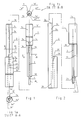
- a first inner part is denoted by 1 and a second inner part by 2.
- Each inner part has a first section 1a and 2a respectively and a second section 1b and 2b respectively.
- the first sections 1a and 2a form sectoral shapes in respective cross sections.
- Each sector has an external surface 1a' and 2a' respectively and parts 1a", 1a"' and 2a", 2a"' extending radially.
- the second section has a circular or round cross-section 1b' and 2b' respectively.
- the sector-shaped sections 1a and 2a thereby have external surfaces 1a' and 2a', which adjoin the circular shape 1b' and 2b' respectively of the second section.
- each inner part can be manufactured from a single rod material of circular or round cross-section and that the said sector-shaped parts 1a and 2a are manufactured by milling away or removing material from the basic material in the form of a rod.
- the first inner part 1 is provided with a combined steering and locking member 3, which extends in the longitudinal direction of the part 1.
- the member is located centrally and has the same central axis 4 as the first unit 1.
- the member 3 may be formed as a round tube which is supported in the unit 1 in a recess 1c in the unit.
- the member 3 is therefore provided with a bearing part 3a at its first end.
- the bearing member is arranged in a recess 1a'''' in the inner parts of the sector-shaped part.
- the member 3 is provided with a bearing part 3b, which projects outside the end surface 1d of the first part.
- the first inner part also has a shoulder surface 1e at the transition between the first and the second sections 1a and 1b.
- the second section 2a is provided with a depression, preferably a curved depression 2c, which adjoins the outer rounded tubular shape of the member 3. The depression therefore serves as a bearing notch for the member 3.
- the inner part 2 is also provided with a recess 2d in the section 2b.
- the recess 2d functions as guide recess for the member 3 on the first inner part 1, the free end 3b of which can be introduced into the recess 2d when the first and second inner parts are brought together.
- the section 2a is provided with an end surface 2e and the section 2b is provided with a shoulder 2f.
- FIG 2 in which the inner parts 1a, 1b and 2a, 2b have been rotated through 90° in relation to the positions according to figure 1.
- the depression 2c in the section 2a can be seen, as can the recess 2d and the end surface 2f. Also visible are the member 3 with its free end 3b and the stop surface 1b.
- the parts 1 and 2 can be brought together in the direction indicated by 5.
- the part 1 is thus applied with the end 3b against the recess 2c with simultaneous telescoping or bringing together of the parts.
- the member 3 and the recess 2c thereby serve as guides for the telescoping movement and the part 3b can mount the recess 2d during the final telescoping sequence.
- This mounting produces a fundamentally rigid connection between the parts in the longitudinal direction.
- a rotatable connection exists.
- the member 3 serves as pivot bearing and the inner parts can be rotated to different torsional positions by means of the pivot bearing 3 and the recess 2c.
- the end surfaces 1e and 2f form limit stops for the telescoping movement between the inner parts 1 and 2.
- the parts 1a", 1a"' and 2a", 2a''' extending radially form torsion limit stops for the reciprocal torsional movements of the parts.
- the parts of the sector-shaped sections extending radially interact in pairs.
- the inner parts are shown in the combined position, which according to the above is defined, among other things, by the end surface 1d on the first section 1a and 2f on the second section 2b.
- the united parts are arranged in an outer tube 6, which encloses the inner parts in a recess 6a. With their external dimensions the sector-shaped sections 1a (and 2a according to the above) connect very accurately with the said recess 6a.
- the damping device formed by the inner and outer parts is arranged in a steering tube 7 of a motor cycle (not shown).
- the parts are connected to upper and lower steering heads 8, 9 in a manner known in the art.
- the steering tube and steering heads on the familiar Yamaha R1 motor cycle may be cited as an example.
- the sections 1b and 2b are provided with sealing rings 10 and 11, which form a seal against the wall of the recess 6a.
- spaces 12 and 13 which in the aforementioned exemplary embodiment may be regarded as having varying sectoral shapes, cf. also below, are obtained between the outsides of the inner parts and the inner wall of the outer part.
- the rotatability of the inner parts in the outer part therefore means that the spaces 12 and 13 vary in size as a function of the reciprocal torsional positions between the first and second inner parts (cf. 1 and 2 above).
- the spaces are to be filled with medium used in the context of damping, for example hydraulic oil with conventional additives, gas, etc. Due to the variations in the sizes of the spaces 12, 13, according to the invention the said medium is transferred between the spaces as a function of the reciprocal torsional positions of the inner parts.
- the medium is transferred between the spaces 12 and 13 via ducts 15, 16, which in this case are arranged in the section 1b and in the outer tube 6 or in part connected to the said outer tube.
- a regulating member 17 Connected to the ducts or to the connection 15, 16 formed by the ducts is a regulating member 17, by means of which the area of the through-flow passage 17a can be adjusted with the aid of a manual regulating member 18.
- the regulating member 17, and the manual member 18 may be of conventional type and will therefore not be described in more detail here. According to the above, a substantial mating accuracy exists between the inner and outer parts, ensuring that the medium does not leak out.
- the said sealing rings 10 and 11 which may be of a type known in the art.
- Figure 5 shows a basic view of the sector-shaped parts 1a and 2a where these assume a middle position in respect of the torsional movement.
- medium 14 in the reduced space 12 is displaced over to the increasing space 13 via the ducts 15', 16' and the regulating member 17', 18'.
- the damping can therefore vary through adjustment of the member 18'.
- the direction of the medium in figure 5 is shown by 20 and 21. If the section 1a is acted upon in the opposite direction to the direction 19, medium is transferred from the thereby diminishing space 13 to the increasing space 12 in opposite directions to the directions 20, 21. It will be appreciated that the damping can be modified by influencing of the through-flow area in the regulating device 17'.
- Figure 6 is intended to show the stage at which the space 12 has been reduced in relation to the situation in the stage according to figure 5, and the space 13 correspondingly increased.
- Figures 7 and 8 show the torsional limit positions in which the space 13 assumes zero size and the space 12 assumes its maximum size or the space 13 assumes its maximum size and the space 12 assumes zero size.
- the radial parts 1a" and 2a" of the shapes interact with one another.
- the straight parts 2a" and 1a"" of the sectoral shapes interact with one another.
- Figure 9 shows a basic view of the steering tube 7 with associated steering heads 8 and 9 fitted to a frame 22 and a front-wheel fork 23 on a motor cycle, not shown further, such as a motor cycle of the said type.
- Figure 10 shows a basic material in the form of machined (ground) round rods 24, 25 having circular or round external dimensions.
- the rod parts may take the form of solid material or take a tubular form. From this material the inner parts in question are manufactured by milling out the aforementioned sector-shaped parts. The external dimensions of the sector-shaped parts or sections are connected to the aforementioned second sections with great accuracy. Boring in the material for the aforementioned bearing recesses can be performed with relative ease.
- the tubular guide and bearing part can be applied to the first part and the second part can be provided with the longitudinal, curved guide slot (cf. 2c in figure 1).
- an outer part 26 which may take the form of a conventional tube, the inside wall 26a of which is machined with the same accuracy as the external surfaces 24a, 25a on the rod parts or inner parts.
- the mating accuracy between external surfaces 24a, 25a and the inner surface 26a may be selected between 2/100 mm and 6/100 mm.
- the ducting system and needle or regulating member arrangement can be conventionally arranged in the inner and/or outer parts by means known in the art.
- Figures 1 and 2 also discloses a chamber x1, in which oil is applied.
- the oil in said chamber is connected with the oil included in the device.
- a movable (floating) piston is shown by x2.
- the piston attain a pressure on the oil in said chamber by means of pressure obtaining devices not disclosed in Figures 1 and 2, but, for example, can comprise a spring(s), pressure generating devices, etc.
- a gas or medium pressure can be arranged beneath the piston.
- the damper will in such a way work preferable pressure function or a pressure generating function which keeps the medium pressure of the medium (the oil), which is conducted or transferred between the parts via the regulating member, on the adjusted value independent of factors which otherwise could change the pressure and in a negative way affect the damping function of the damper.
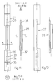
- Figures 11, 11a, 11b and 12 show separation of parts 27, 28, which can be put together, compare above.
- the parts may be made by individually produced parts which are assembled.
- the part 27 has bearings 29, 30 to pins 31, 32 applied on the part 28.
- the chamber is here shown with 33 and the piston with 34.
- Pressure causing device in the shape of a spring is symbolized with 35.
Landscapes
- Engineering & Computer Science (AREA)
- Mechanical Engineering (AREA)
- General Engineering & Computer Science (AREA)
- Fluid-Damping Devices (AREA)
Applications Claiming Priority (2)
| Application Number | Priority Date | Filing Date | Title |
|---|---|---|---|
| SE0300300A SE525868C2 (sv) | 2003-02-06 | 2003-02-06 | Dämpanordning innefattande inner- och ytterdelar samt förfarande vid sådan anordning |
| SE0300300 | 2003-02-06 |
Publications (2)
| Publication Number | Publication Date |
|---|---|
| EP1445182A2 true EP1445182A2 (de) | 2004-08-11 |
| EP1445182A3 EP1445182A3 (de) | 2007-05-02 |
Family
ID=20290314
Family Applications (1)
| Application Number | Title | Priority Date | Filing Date |
|---|---|---|---|
| EP03445112A Withdrawn EP1445182A3 (de) | 2003-02-06 | 2003-10-14 | Dämpfungseinrichtung mit Innen- und Aussenteilen zusammen mit Verfahren und Verwendung einer solchen Dämpfungseinrichtung |
Country Status (4)
| Country | Link |
|---|---|
| US (1) | US20040149528A1 (de) |
| EP (1) | EP1445182A3 (de) |
| JP (1) | JP2004239440A (de) |
| SE (1) | SE525868C2 (de) |
Cited By (3)
| Publication number | Priority date | Publication date | Assignee | Title |
|---|---|---|---|---|
| WO2006095032A1 (es) * | 2005-03-04 | 2006-09-14 | Juan Lorenzo Real Rebollo | Sistema de suspensión para horquillas delanteras de motocicletas |
| EP1705397A3 (de) * | 2005-02-17 | 2008-01-02 | Ralph S. Norman | Flüssigkeitsdämpfer |
| DE102016216488A1 (de) * | 2016-09-01 | 2018-03-01 | Bayerische Motoren Werke Aktiengesellschaft | Lenkrohr für ein Fahrzeug sowie Lenkung für ein Fahrzeug |
Family Cites Families (6)
| Publication number | Priority date | Publication date | Assignee | Title |
|---|---|---|---|---|
| DE2635906A1 (de) * | 1976-08-10 | 1978-02-16 | Wilhelm Hense & Co Gmbh | Hydraulische daempfungsvorrichtung |
| EP0524607A1 (de) * | 1991-07-22 | 1993-01-27 | Toyoda Koki Kabushiki Kaisha | Dreh-Stossdämpfer |
| US5516133A (en) * | 1994-08-04 | 1996-05-14 | Stabletec, Inc. | Steering stabilizer for bicycles |
| US6145637A (en) * | 1995-02-23 | 2000-11-14 | Hopey; Timothy C. | Steering damper in and for vehicles |
| US5927740A (en) * | 1996-08-14 | 1999-07-27 | Hopey; Timothy C. | Steering damper in and for vehicles |
| EP1300328A1 (de) * | 2001-10-02 | 2003-04-09 | Ducati Motor Holding S.p.A. | Hydraulischer Lenkungsdämpfer für ein Kraftfahrzeug |
-
2003
- 2003-02-06 SE SE0300300A patent/SE525868C2/sv not_active IP Right Cessation
- 2003-10-14 EP EP03445112A patent/EP1445182A3/de not_active Withdrawn
- 2003-11-03 US US10/698,941 patent/US20040149528A1/en not_active Abandoned
-
2004
- 2004-02-06 JP JP2004030428A patent/JP2004239440A/ja active Pending
Cited By (5)
| Publication number | Priority date | Publication date | Assignee | Title |
|---|---|---|---|---|
| EP1705397A3 (de) * | 2005-02-17 | 2008-01-02 | Ralph S. Norman | Flüssigkeitsdämpfer |
| WO2006095032A1 (es) * | 2005-03-04 | 2006-09-14 | Juan Lorenzo Real Rebollo | Sistema de suspensión para horquillas delanteras de motocicletas |
| ES2259912A1 (es) * | 2005-03-04 | 2006-10-16 | Juan Lorenzo Real Rebollo | Sistema de suspension para horquillas delanteras de motocicletas. |
| ES2259912B1 (es) * | 2005-03-04 | 2007-12-01 | Juan Lorenzo Real Rebollo | Sistema de suspension para horquillas delanteras de motocicletas. |
| DE102016216488A1 (de) * | 2016-09-01 | 2018-03-01 | Bayerische Motoren Werke Aktiengesellschaft | Lenkrohr für ein Fahrzeug sowie Lenkung für ein Fahrzeug |
Also Published As
| Publication number | Publication date |
|---|---|
| SE0300300D0 (sv) | 2003-02-06 |
| US20040149528A1 (en) | 2004-08-05 |
| EP1445182A3 (de) | 2007-05-02 |
| SE525868C2 (sv) | 2005-05-17 |
| JP2004239440A (ja) | 2004-08-26 |
| SE0300300L (sv) | 2004-08-07 |
Similar Documents
| Publication | Publication Date | Title |
|---|---|---|
| AU615564B2 (en) | Shock absorber with damping valve structure having wide range variable damping characteristics | |
| KR920008873Y1 (ko) | 유압 완충기 | |
| KR102294332B1 (ko) | 완충기 | |
| JPH0438114Y2 (de) | ||
| JPH0218359Y2 (de) | ||
| JPH07233840A (ja) | 減衰力可変型ショックアブソーバ | |
| IT8312534A1 (it) | Ammortizzatore a fluido particolarmente adatto per automobili, aeromobili e simili | |
| JP2001208123A (ja) | 油圧緩衝器 | |
| US20200256417A1 (en) | Valve and shock absorber | |
| EP1445182A2 (de) | Dämpfungseinrichtung mit Innen- und Aussenteilen zusammen mit Verfahren und Verwendung einer solchen Dämpfungseinrichtung | |
| JPH05332388A (ja) | 減衰力調整式油圧緩衝器 | |
| US20060179654A1 (en) | Method and adjusting the throttling action of a valve | |
| JP4417823B2 (ja) | 緩衝器 | |
| JP7054063B2 (ja) | スプール弁型ショックアブソーバ | |
| JP3383865B2 (ja) | 油圧緩衝器 | |
| JPH07269628A (ja) | ダンパ | |
| JPS6227726Y2 (de) | ||
| US7052004B2 (en) | Hydraulically damping rubber bearing | |
| JP2857403B2 (ja) | 減衰力可変型液圧緩衝器 | |
| JP2002521630A (ja) | 油圧ダンパの抵抗力を調節する方法とそれを実現する装置(変形) | |
| JP2918250B2 (ja) | 減衰力可変型液圧緩衝器 | |
| DE2604467A1 (de) | Schwingungsdaempfer, insbesondere fuer motorfahrzeuge | |
| JPH0727166A (ja) | ショックアブソーバの減衰力調整装置 | |
| JP2524793Y2 (ja) | 減衰力可変型液圧緩衝器 | |
| JPH11344069A (ja) | 油圧緩衝器の減衰力発生構造 |
Legal Events
| Date | Code | Title | Description |
|---|---|---|---|
| PUAI | Public reference made under article 153(3) epc to a published international application that has entered the european phase |
Free format text: ORIGINAL CODE: 0009012 |
|
| AK | Designated contracting states |
Kind code of ref document: A2 Designated state(s): AT BE BG CH CY CZ DE DK EE ES FI FR GB GR HU IE IT LI LU MC NL PT RO SE SI SK TR |
|
| AX | Request for extension of the european patent |
Extension state: AL LT LV MK |
|
| PUAL | Search report despatched |
Free format text: ORIGINAL CODE: 0009013 |
|
| AK | Designated contracting states |
Kind code of ref document: A3 Designated state(s): AT BE BG CH CY CZ DE DK EE ES FI FR GB GR HU IE IT LI LU MC NL PT RO SE SI SK TR |
|
| AX | Request for extension of the european patent |
Extension state: AL LT LV MK |
|
| 17P | Request for examination filed |
Effective date: 20071025 |
|
| AKX | Designation fees paid |
Designated state(s): AT BE BG CH CY CZ DE DK EE ES FI FR GB GR HU IE IT LI LU MC NL PT RO SE SI SK TR |
|
| 17Q | First examination report despatched |
Effective date: 20090702 |
|
| STAA | Information on the status of an ep patent application or granted ep patent |
Free format text: STATUS: THE APPLICATION IS DEEMED TO BE WITHDRAWN |
|
| 18D | Application deemed to be withdrawn |
Effective date: 20091113 |