EP1445206A2 - Verpackung für Zweikomponentenprodukte - Google Patents
Verpackung für Zweikomponentenprodukte Download PDFInfo
- Publication number
- EP1445206A2 EP1445206A2 EP04001278A EP04001278A EP1445206A2 EP 1445206 A2 EP1445206 A2 EP 1445206A2 EP 04001278 A EP04001278 A EP 04001278A EP 04001278 A EP04001278 A EP 04001278A EP 1445206 A2 EP1445206 A2 EP 1445206A2
- Authority
- EP
- European Patent Office
- Prior art keywords
- container
- lid
- edge
- containers
- bead
- Prior art date
- Legal status (The legal status is an assumption and is not a legal conclusion. Google has not performed a legal analysis and makes no representation as to the accuracy of the status listed.)
- Granted
Links
Images
Classifications
-
- B—PERFORMING OPERATIONS; TRANSPORTING
- B65—CONVEYING; PACKING; STORING; HANDLING THIN OR FILAMENTARY MATERIAL
- B65D—CONTAINERS FOR STORAGE OR TRANSPORT OF ARTICLES OR MATERIALS, e.g. BAGS, BARRELS, BOTTLES, BOXES, CANS, CARTONS, CRATES, DRUMS, JARS, TANKS, HOPPERS, FORWARDING CONTAINERS; ACCESSORIES, CLOSURES, OR FITTINGS THEREFOR; PACKAGING ELEMENTS; PACKAGES
- B65D21/00—Nestable, stackable or joinable containers; Containers of variable capacity
- B65D21/02—Containers specially shaped, or provided with fittings or attachments, to facilitate nesting, stacking, or joining together
- B65D21/0209—Containers specially shaped, or provided with fittings or attachments, to facilitate nesting, stacking, or joining together stackable or joined together one-upon-the-other in the upright or upside-down position
- B65D21/0224—Auxiliary removable stacking elements other than covers
-
- B—PERFORMING OPERATIONS; TRANSPORTING
- B65—CONVEYING; PACKING; STORING; HANDLING THIN OR FILAMENTARY MATERIAL
- B65D—CONTAINERS FOR STORAGE OR TRANSPORT OF ARTICLES OR MATERIALS, e.g. BAGS, BARRELS, BOTTLES, BOXES, CANS, CARTONS, CRATES, DRUMS, JARS, TANKS, HOPPERS, FORWARDING CONTAINERS; ACCESSORIES, CLOSURES, OR FITTINGS THEREFOR; PACKAGING ELEMENTS; PACKAGES
- B65D43/00—Lids or covers for rigid or semi-rigid containers
- B65D43/02—Removable lids or covers
- B65D43/0202—Removable lids or covers without integral tamper element
- B65D43/0214—Removable lids or covers without integral tamper element secured only by friction or gravity
- B65D43/0218—Removable lids or covers without integral tamper element secured only by friction or gravity on both the inside and the outside of the mouth of the container
-
- B—PERFORMING OPERATIONS; TRANSPORTING
- B65—CONVEYING; PACKING; STORING; HANDLING THIN OR FILAMENTARY MATERIAL
- B65D—CONTAINERS FOR STORAGE OR TRANSPORT OF ARTICLES OR MATERIALS, e.g. BAGS, BARRELS, BOTTLES, BOXES, CANS, CARTONS, CRATES, DRUMS, JARS, TANKS, HOPPERS, FORWARDING CONTAINERS; ACCESSORIES, CLOSURES, OR FITTINGS THEREFOR; PACKAGING ELEMENTS; PACKAGES
- B65D45/00—Clamping or other pressure-applying devices for securing or retaining closure members
- B65D45/32—Clamping or other pressure-applying devices for securing or retaining closure members for applying radial or radial and axial pressure, e.g. contractible bands encircling closure member
- B65D45/34—Clamping or other pressure-applying devices for securing or retaining closure members for applying radial or radial and axial pressure, e.g. contractible bands encircling closure member lever-operated
-
- B—PERFORMING OPERATIONS; TRANSPORTING
- B65—CONVEYING; PACKING; STORING; HANDLING THIN OR FILAMENTARY MATERIAL
- B65D—CONTAINERS FOR STORAGE OR TRANSPORT OF ARTICLES OR MATERIALS, e.g. BAGS, BARRELS, BOTTLES, BOXES, CANS, CARTONS, CRATES, DRUMS, JARS, TANKS, HOPPERS, FORWARDING CONTAINERS; ACCESSORIES, CLOSURES, OR FITTINGS THEREFOR; PACKAGING ELEMENTS; PACKAGES
- B65D81/00—Containers, packaging elements, or packages, for contents presenting particular transport or storage problems, or adapted to be used for non-packaging purposes after removal of contents
- B65D81/32—Containers, packaging elements, or packages, for contents presenting particular transport or storage problems, or adapted to be used for non-packaging purposes after removal of contents for packaging two or more different materials which must be maintained separate prior to use in admixture
- B65D81/3205—Separate rigid or semi-rigid containers joined to each other at their external surfaces
-
- B—PERFORMING OPERATIONS; TRANSPORTING
- B65—CONVEYING; PACKING; STORING; HANDLING THIN OR FILAMENTARY MATERIAL
- B65D—CONTAINERS FOR STORAGE OR TRANSPORT OF ARTICLES OR MATERIALS, e.g. BAGS, BARRELS, BOTTLES, BOXES, CANS, CARTONS, CRATES, DRUMS, JARS, TANKS, HOPPERS, FORWARDING CONTAINERS; ACCESSORIES, CLOSURES, OR FITTINGS THEREFOR; PACKAGING ELEMENTS; PACKAGES
- B65D2543/00—Lids or covers essentially for box-like containers
- B65D2543/00009—Details of lids or covers for rigid or semi-rigid containers
- B65D2543/00018—Overall construction of the lid
- B65D2543/00064—Shape of the outer periphery
- B65D2543/00074—Shape of the outer periphery curved
- B65D2543/00092—Shape of the outer periphery curved circular
-
- B—PERFORMING OPERATIONS; TRANSPORTING
- B65—CONVEYING; PACKING; STORING; HANDLING THIN OR FILAMENTARY MATERIAL
- B65D—CONTAINERS FOR STORAGE OR TRANSPORT OF ARTICLES OR MATERIALS, e.g. BAGS, BARRELS, BOTTLES, BOXES, CANS, CARTONS, CRATES, DRUMS, JARS, TANKS, HOPPERS, FORWARDING CONTAINERS; ACCESSORIES, CLOSURES, OR FITTINGS THEREFOR; PACKAGING ELEMENTS; PACKAGES
- B65D2543/00—Lids or covers essentially for box-like containers
- B65D2543/00009—Details of lids or covers for rigid or semi-rigid containers
- B65D2543/00435—Lids secured to an intermediate ring or like annular member fixed to the container mouth
-
- B—PERFORMING OPERATIONS; TRANSPORTING
- B65—CONVEYING; PACKING; STORING; HANDLING THIN OR FILAMENTARY MATERIAL
- B65D—CONTAINERS FOR STORAGE OR TRANSPORT OF ARTICLES OR MATERIALS, e.g. BAGS, BARRELS, BOTTLES, BOXES, CANS, CARTONS, CRATES, DRUMS, JARS, TANKS, HOPPERS, FORWARDING CONTAINERS; ACCESSORIES, CLOSURES, OR FITTINGS THEREFOR; PACKAGING ELEMENTS; PACKAGES
- B65D2543/00—Lids or covers essentially for box-like containers
- B65D2543/00009—Details of lids or covers for rigid or semi-rigid containers
- B65D2543/00444—Contact between the container and the lid
- B65D2543/00481—Contact between the container and the lid on the inside or the outside of the container
- B65D2543/0049—Contact between the container and the lid on the inside or the outside of the container on the inside, or a part turned to the inside of the mouth of the container
- B65D2543/00509—Cup
-
- B—PERFORMING OPERATIONS; TRANSPORTING
- B65—CONVEYING; PACKING; STORING; HANDLING THIN OR FILAMENTARY MATERIAL
- B65D—CONTAINERS FOR STORAGE OR TRANSPORT OF ARTICLES OR MATERIALS, e.g. BAGS, BARRELS, BOTTLES, BOXES, CANS, CARTONS, CRATES, DRUMS, JARS, TANKS, HOPPERS, FORWARDING CONTAINERS; ACCESSORIES, CLOSURES, OR FITTINGS THEREFOR; PACKAGING ELEMENTS; PACKAGES
- B65D2543/00—Lids or covers essentially for box-like containers
- B65D2543/00009—Details of lids or covers for rigid or semi-rigid containers
- B65D2543/00444—Contact between the container and the lid
- B65D2543/00481—Contact between the container and the lid on the inside or the outside of the container
- B65D2543/00537—Contact between the container and the lid on the inside or the outside of the container on the outside, or a part turned to the outside of the mouth of the container
-
- B—PERFORMING OPERATIONS; TRANSPORTING
- B65—CONVEYING; PACKING; STORING; HANDLING THIN OR FILAMENTARY MATERIAL
- B65D—CONTAINERS FOR STORAGE OR TRANSPORT OF ARTICLES OR MATERIALS, e.g. BAGS, BARRELS, BOTTLES, BOXES, CANS, CARTONS, CRATES, DRUMS, JARS, TANKS, HOPPERS, FORWARDING CONTAINERS; ACCESSORIES, CLOSURES, OR FITTINGS THEREFOR; PACKAGING ELEMENTS; PACKAGES
- B65D2543/00—Lids or covers essentially for box-like containers
- B65D2543/00009—Details of lids or covers for rigid or semi-rigid containers
- B65D2543/00444—Contact between the container and the lid
- B65D2543/00481—Contact between the container and the lid on the inside or the outside of the container
- B65D2543/00555—Contact between the container and the lid on the inside or the outside of the container on both the inside and the outside
Definitions
- the present invention relates to a packaging for Two-component products with a first upper container and a second lower container, each with a lid have, the first upper container for formation a storage and transport unit on the lid of the second lower container arranged and detachable on this is fixed.
- Such packaging for two-component products are known.
- the first larger one is used for this type of packaging Containers, for example, to hold one component of a paint, while in the second lower smaller container an additional component, for example a low viscosity hardener that fill in the larger container is housed.
- a packaging for two-component products with the features the preamble of claim 1 is on the market. This is the first in this known packaging large containers in the lid of the smaller second container locked without further securing element. With a such packaging has had good results however, the attachment between the two containers, the heavy loads during the storage and transport phase is still in need of improvement.
- the present invention has for its object a To create packaging of the specified type, which can be found at a particularly good handling by a special good and secure fixation between the containers.
- the lid of the second lower container at a distance from its edge that overlaps a curl of the second lower container, has a bead that is higher than the edge and concentric to it, on which the bottom of the first upper container is supported, the lower edge area of the first upper container has a radially recessed area and an adjoining lower, radially projecting edge with an approximately horizontal top, the lower edge of the first upper container engages at least partially in the annular groove formed between the edge and the bead of the lid of the second lower container, such that the upper sides of both edges are arranged at approximately the same height, for fastening both containers to one another a clamping ring with its wider upper flange comes into contact with the upper sides of both edges and the lid of the second lower container has a central opening with a closure, the maximum height of which in the state closing the opening is less than the height of the lid bead.
- the first upper are larger Container containing, for example, a paint
- the second lower smaller container for example has a hardener for this paint, connected to each other via a tension ring according to the invention with its wider upper flange on the Tops of the edge of the lid of the lower container and of the lower edge of the upper container.
- the clamping ring acts directly in the tensioned state Opposing axial forces trying to separate both containers to separate.
- the tension ring therefore bumps with his upper flange not only perpendicular to the wall of the upper container, but also lies, as mentioned, on the both edges so that a separation of the upper container is counteracted immediately by the lower container while in the prior art mentioned at the beginning of the clamping ring only applies a radially directed force so that the Relative danger of possible axial movements of the containers to each other when appropriate forces occur. According to the invention, this makes it particularly safe Fixation of both containers to each other reached.
- the lid of the second lower container is on the lid of the second lower container at a distance from the edge of the lid and concentric a bead higher than the edge provided the top of which is the bearing for receiving the upper Container forms.
- the upper container is thus supported starting on the top of the bead that is so tall is that a central in the lid of the second lower container Opening with associated closure may be provided can, the maximum height of the closure in the opening closing condition is less than the height of the cover bead.
- the lower smaller container is therefore despite the Placement of the upper larger container on its lid provided with an opening with a closure so that the smaller Container into the larger container in a convenient way can be emptied. For this, the attachment between the two containers, i.e.
- the tension ring relaxes, the upper container removed from the lower container and the Closure from that provided in the lid of the lower container Opening opened, after which the smaller container in the larger container emptied after opening its lid can be.
- the invention can thus trained packaging for two-component products in addition to a particularly good fixation of the container, a more convenient one and easier handling than in the prior art achieve.
- a clamping ring is used Attach the two containers to each other.
- This The clamping ring has two functions: on the one hand, it serves the the aforementioned fastening of the containers to one another, on the other hand, it is used to attach the cover to the second lower container, so that in the transport and storage phase the packaging according to the invention in addition to a prevention the separation of the two containers from each other also ensured is that the lid is not from the lower container can solve.
- the clamping ring engages with its lower one Flange the top edge (the curl) of the bottom Container, so that a safe system in this area the clamping ring is guaranteed, especially a Bearing the flange of the clamping ring against a radial surface of the lower container is reached.
- the upper container can also be used to secure its lid be provided with a clamping ring on the container.
- the lid of the second lower container preferably has an approximately ⁇ -shaped edge.
- an edge closes the also preferably ⁇ -shaped Bead radially inwards, then in the radial direction further inward is an essentially flat lid base to the central opening with a lock follows.
- a sealing ring which for a tight seal between the top edge (the curling) of the second lower container and the lid provides.
- the clamping ring used according to the invention can be of a conventional type Be of a construction type and must be detailed at this point not be described.
- Such clamping rings are known to the person skilled in the art known and are generally C-shaped with a upper flange, a lower flange and a web formed, with the used according to the invention Clamping ring the upper flange is longer than that lower flange, as it recesses into the radially recessed Area of the lower wall area of the first upper Container extends and with the top of the radially protruding bottom of the upper container in plant occurs.
- the first upper container can also be a suitable handle own, at opposite points of the container wall is attached. In this way, the Transport the upper container easily.
- Both containers are made of tinplate, namely both actual container as well as the container lid.
- the upper container preferably has one on its hull or several beads. It can be, for example around an upper stacking bead and / or one or more reinforcing beads act. Instead of reinforcing beads Corresponding ring grooves (grooves) can also be arranged in the fuselage his.
- the two containers shown in Figures 1 and 2 form a packaging for Two-component products, for example in the upper A paint container and the corresponding one in the lower container Hardener for the paint is included.
- the Both containers are connected using a clamping ring, this clamping ring at the same time the lid on lower container fixed.
- Another clamping ring is used for Fix the lid of the upper container.
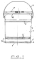
- FIG. 1 shows a first upper container 1 with a slightly conical hull 3 and inserted into the container Lid 10.
- a Carrying handle 2 is provided, which is attached to the fuselage in two places is.
- the fuselage also has a stacking bead 7 and two reinforcement grooves 8.
- the lower wall area of the container body 3 has one radially recessed area 5 and an attached to it subsequent lower radially projecting edge 6 with approximately horizontal top.
- the container bottom 4 is opposite the bottom of the edge 6 is arranged offset upwards.
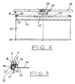
- the associated second lower container 11 is the packaging shown in the side view in Figure 2. It is smaller than the first upper container and is approximately cylindrical Shape. At the top of the container 11 is a curl 13 provided. There is a similar one at the bottom Rolling 12.
- the associated container lid 14 is in the Container 11 shown separate state and has a central opening 15, which can be closed via a clamping cover 20 is. Otherwise, the cover 14 of the second lower container 11 at a distance from its curling 13 of the second lower container overlapping edge 16 a higher than the edge 16 and formed concentrically to this Beading 17 on which is in the stacked state both containers the bottom 4 of the upper container 1 supported. Both the lid edge 16 and the bead 17 are approximately ⁇ -shaped, being within the edge 16 a suitable sealing ring 21 is arranged.
- a clamping ring 18 is shown in Figure 2, the both the lid 14 on the container 11 and both containers fixed to each other.
- the clamping ring 18 has, as in FIG. 3 shown a short lower flange 22 and a longer one upper flange 23, which are connected to one another via a web are. Otherwise, the clamping ring 18 is more conventional Design and via a suitable clamping device 19 braced.
- Figure 3 shows a connection detail of the two containers in the superimposed Condition with tension ring attached Vertical section.
- the lower container 11 with its Rolling 13 shown at the top. This rolling 13 is overlapped by the edge 16 of the container lid 14, wherein the sealing ring 21 arranged between them is compressed becomes.
- an annular groove 24 is disposed inward therefrom an annular groove 24, in which in the attached state of the upper Container 1 engages the lower edge 6, and so wide that the tops of the lid rim 16 and the bottom Edge 6 of the upper container 1 is arranged approximately the same height are.
- the bead 17 of the lid 14 is so high that the clamp closure 20 inserted into the lid opening 15 placing the upper container 1 on the lid 14 not disabled.
- the upper container When the upper container is in place lies its bottom 4 on the top of the bead 17th on.
- After loosening the clamping ring 18 and separating the two Containers from each other can therefore be the content of the bottom Container in a convenient way by removing the clamp 20 to be emptied into the upper container after whose cover has been removed. Piercing the Lid 14 is no longer required.
Landscapes
- Engineering & Computer Science (AREA)
- Mechanical Engineering (AREA)
- Closures For Containers (AREA)
- Stackable Containers (AREA)
- Details Of Rigid Or Semi-Rigid Containers (AREA)
- Packaging Of Annular Or Rod-Shaped Articles, Wearing Apparel, Cassettes, Or The Like (AREA)
- Packages (AREA)
Abstract
Description
der Deckel des zweiten unteren Behälters mit Abstand von seinem eine Rollierung des zweiten unteren Behälters übergreifenden Rand eine höher als der Rand und konzentrisch zu diesem ausgebildete Sicke aufweist, auf der sich der Boden des ersten oberen Behälters abstützt,
der untere Randbereich des ersten oberen Behälters einen radial zurückspringenden Bereich und einen sich hieran anschließenden unteren radial vorstehenden Rand mit etwa horizontaler Oberseite aufweist,
der untere Rand des ersten oberen Behälters mindestens teilweise in die zwischen dem Rand und der Sicke des Dekkels des zweiten unteren Behälters ausgebildete Ringnut eingreift, derart, daß die Oberseiten beider Ränder etwa gleich hoch angeordnet sind,
zur Befestigung beider Behälter aneinander ein Spannring mit seinem breiteren oberen Flansch mit den Oberseiten beider Ränder in Anlage tritt und
der Deckel des zweiten unteren Behälters eine zentrale Öffnung mit Verschluß besitzt, dessen Maximalhöhe im die Öffnung verschließenden Zustand geringer ist als die Höhe der Deckelsicke.
- Figur 1
- den oberen Behälter einer Verpackung für Zweikomponenten-Produkte in der Seitenansicht mit getrennt gezeigtem Spannring;
- Figur 2
- den unteren Behälter der gleichen Verpackung in der Seitenansicht mit separat dargestelltem Dekkel und Spannring; und
- Figur 3
- einen Vertikalschnitt durch den Verbindungsbereich zwischen oberem und unterem Behälter mit aufgebrachtem Spannring.
Claims (6)
- Verpackung für Zweikomponenten-Produkte mit einem ersten oberen Behälter und einem zweiten unteren Behälter, die jeweils einen Deckel aufweisen, wobei der erste obere Behälter zur Ausbildung einer Lager- und Transporteinheit auf dem Deckel des zweiten unteren Behälters angeordnet und an diesem lösbar fixiert ist,
dadurch gekennzeichnet, daß der Deckel (14) des zweiten unteren Behälters (11) mit Abstand von seinem eine Rollierung (13) des zweiten unteren Behälters (11) übergreifenden Rand (16) eine höher als der Rand (16) und konzentrisch zu diesem ausgebildete Sicke (17) aufweist, auf der sich der Boden (4) des ersten oberen Behälters (1) abstützt,
daß der untere Wandbereich des ersten oberen Behälters (1) einen radial zurückspringenden Bereich (5) und einen sich hieran anschließenden unteren radial vorstehenden Rand (6) mit etwa horizontaler Oberseite aufweist,
daß der untere Rand (6) des ersten oberen Behälters (1) mindestens teilweise in die zwischen dem Rand (16) und der Sicke (17) des Deckels (14) des zweiten unteren Behälters (11) ausgebildete Ringnut (24) eingreift, derart, daß die Oberseiten beider Ränder (16, 6) etwa gleich hoch angeordnet sind,
daß zur Befestigung beider Behälter (1, 11) aneinander ein Spannring (18) mit seinem breiteren oberen Flansch (23) mit den Oberseiten beider Ränder (16, 6) in Anlage tritt und
daß der Deckel (14) des zweiten unteren Behälters (11) eine zentrale Öffnung (15) mit Verschluß (20) besitzt, dessen Maximalhöhe im die Öffnung (15) verschließenden Zustand geringer ist als die Höhe der Deckelsicke (17). - Verpackung nach Anspruch 1, dadurch gekennzeichnet, daß der erste obere Behälter (1) zur Sicherung seines Deckels (10) am Behälter (1) einen Spannring (9) aufweist.
- Verpackung nach Anspruch 1 oder 2, dadurch gekennzeichnet, daß der Deckel (14) des zweiten unteren Behälters (11) einen im Schnitt etwa Ω-förmig ausgebildeten Rand (16) besitzt.
- Verpackung nach einem der vorangehenden Ansprüche, dadurch gekennzeichnet, daß innerhalb des Deckelrandes (16) des zweiten unteren Behälters (11) ein Dichtungsring (21) angeordnet ist.
- Verpackung nach einem der vorangehenden Ansprüche, dadurch gekennzeichnet, daß der erste obere Behälter (1) an seinem Rumpf (3) eine oder mehrere Sicken (7) und/oder Riefen (8) aufweist.
- Verpackung nach einem der vorangehenden Ansprüche, dadurch gekennzeichnet, daß der erste obere Behälter (1) einen gegenüber seinem unteren Rand (6) zurückspringenden Boden (4) besitzt, der sich im aufeinandergesetzten Zustand der Behälter auf der Oberseite der Deckelsicke (17) abstützt.
Applications Claiming Priority (2)
| Application Number | Priority Date | Filing Date | Title |
|---|---|---|---|
| DE10304302A DE10304302A1 (de) | 2003-02-04 | 2003-02-04 | Verpackung für Zweikomponenten Produkte |
| DE10304302 | 2003-02-04 |
Publications (3)
| Publication Number | Publication Date |
|---|---|
| EP1445206A2 true EP1445206A2 (de) | 2004-08-11 |
| EP1445206A3 EP1445206A3 (de) | 2004-08-18 |
| EP1445206B1 EP1445206B1 (de) | 2006-08-02 |
Family
ID=32603122
Family Applications (1)
| Application Number | Title | Priority Date | Filing Date |
|---|---|---|---|
| EP04001278A Expired - Lifetime EP1445206B1 (de) | 2003-02-04 | 2004-01-22 | Verpackung für Zweikomponentenprodukte |
Country Status (4)
| Country | Link |
|---|---|
| EP (1) | EP1445206B1 (de) |
| AT (1) | ATE334891T1 (de) |
| DE (2) | DE10304302A1 (de) |
| ES (1) | ES2270185T3 (de) |
Families Citing this family (1)
| Publication number | Priority date | Publication date | Assignee | Title |
|---|---|---|---|---|
| DE102007045299A1 (de) | 2007-09-21 | 2009-04-02 | Construction Research & Technology Gmbh | Verpackung für 2-Komponenten-Produkte |
Family Cites Families (4)
| Publication number | Priority date | Publication date | Assignee | Title |
|---|---|---|---|---|
| US1984570A (en) * | 1933-09-09 | 1934-12-18 | Continental Can Co | Double compartment metal package |
| DE9304892U1 (de) * | 1993-03-31 | 1993-05-27 | Züchner Verpackungen GmbH & Co, 3370 Seesen | Gebinde für Zweikomponentensysteme |
| DE9320615U1 (de) * | 1993-05-26 | 1994-10-06 | Niederrheinische Blechwarenfabrik GmbH, 47239 Duisburg | Verpackung für Zweikomponenten-Produkte |
| DE9317529U1 (de) * | 1993-11-04 | 1994-03-03 | Muhr & Söhne GmbH + Co. KG, 57439 Attendorn | Doppelbehälter für Mehrkomponentenprodukte |
-
2003
- 2003-02-04 DE DE10304302A patent/DE10304302A1/de not_active Withdrawn
-
2004
- 2004-01-22 EP EP04001278A patent/EP1445206B1/de not_active Expired - Lifetime
- 2004-01-22 AT AT04001278T patent/ATE334891T1/de active
- 2004-01-22 DE DE502004001057T patent/DE502004001057D1/de not_active Expired - Lifetime
- 2004-01-22 ES ES04001278T patent/ES2270185T3/es not_active Expired - Lifetime
Also Published As
| Publication number | Publication date |
|---|---|
| EP1445206B1 (de) | 2006-08-02 |
| DE10304302A1 (de) | 2004-08-12 |
| EP1445206A3 (de) | 2004-08-18 |
| DE502004001057D1 (de) | 2006-09-14 |
| ATE334891T1 (de) | 2006-08-15 |
| ES2270185T3 (es) | 2007-04-01 |
Similar Documents
| Publication | Publication Date | Title |
|---|---|---|
| DE69005109T2 (de) | Wiederverschliessbarer deckel mit originalitätssicherung. | |
| DE2432444A1 (de) | Faelschungssicherer verschluss | |
| DE2215778A1 (de) | Behälterverschluß | |
| DE2921627A1 (de) | Verschluss fuer einen behaelter | |
| DE7816353U1 (de) | Einteiliger Originalitaetsbehaelter | |
| DE2924908A1 (de) | Kunststoff-verschluss fuer einen behaelter | |
| DE10260225B4 (de) | Behälter aus Kunststoff, insbesondere Eimer | |
| DE3442152C2 (de) | ||
| DE8208599U1 (de) | Mit einem Eindrueckdeckel verschlossener Verpackungsbehaelter aus Blech | |
| DE2753951A1 (de) | Behaelterdeckel | |
| EP0410141B1 (de) | Spannringverschluss für Behälter aus Blech, wie Eimer, Hobbock oder dgl., mit einem Eindrückdeckel | |
| EP1445206B1 (de) | Verpackung für Zweikomponentenprodukte | |
| EP1608564A1 (de) | Dose mit einem folienverschluss | |
| EP0294781B1 (de) | Vorrichtung zum Sichern des Deckels einer Dose, insbesondere Lackdose | |
| EP0630827B1 (de) | Verpackung für Zweikomponenten-Produkte | |
| EP0535383A2 (de) | Behälter aus Metall oder einer Metall-Verbundfolie | |
| DE4204427C1 (en) | Bottle closure with bottle neck closed by elastomer sealing element - involves holder cap with through hole in its face wall and tear-off element on upper side of face wall | |
| EP0098576A2 (de) | Deckel für Einwegbehälter | |
| EP0373242B1 (de) | Verpackung für Zweikomponenten-Produkte | |
| DE69500480T2 (de) | Verschlussvorrichtung für Flaschen | |
| DE69202818T2 (de) | Verschlussring für Metalldose mit Deckel. | |
| EP0921985B1 (de) | Verfahren zur herstellung eines befüllten behälters | |
| DE8426661U1 (de) | Drehverschluss fuer Behaelter | |
| EP1186547B1 (de) | Behälter mit Deckelsicherung | |
| DE3442344A1 (de) | Behaelterverschluss mit metallabdeckung |
Legal Events
| Date | Code | Title | Description |
|---|---|---|---|
| PUAI | Public reference made under article 153(3) epc to a published international application that has entered the european phase |
Free format text: ORIGINAL CODE: 0009012 |
|
| PUAL | Search report despatched |
Free format text: ORIGINAL CODE: 0009013 |
|
| AK | Designated contracting states |
Kind code of ref document: A2 Designated state(s): AT BE BG CH CY CZ DE DK EE ES FI FR GB GR HU IE IT LI LU MC NL PT RO SE SI SK TR |
|
| AX | Request for extension of the european patent |
Extension state: AL LT LV MK |
|
| AK | Designated contracting states |
Kind code of ref document: A3 Designated state(s): AT BE BG CH CY CZ DE DK EE ES FI FR GB GR HU IE IT LI LU MC NL PT RO SE SI SK TR |
|
| AX | Request for extension of the european patent |
Extension state: AL LT LV MK |
|
| 17P | Request for examination filed |
Effective date: 20050215 |
|
| AKX | Designation fees paid |
Designated state(s): AT BE BG CH CY CZ DE DK EE ES FI FR GB GR HU IE IT LI LU MC NL PT RO SE SI SK TR |
|
| GRAP | Despatch of communication of intention to grant a patent |
Free format text: ORIGINAL CODE: EPIDOSNIGR1 |
|
| GRAS | Grant fee paid |
Free format text: ORIGINAL CODE: EPIDOSNIGR3 |
|
| GRAA | (expected) grant |
Free format text: ORIGINAL CODE: 0009210 |
|
| AK | Designated contracting states |
Kind code of ref document: B1 Designated state(s): AT BE BG CH CY CZ DE DK EE ES FI FR GB GR HU IE IT LI LU MC NL PT RO SE SI SK TR |
|
| PG25 | Lapsed in a contracting state [announced via postgrant information from national office to epo] |
Ref country code: IT Free format text: LAPSE BECAUSE OF FAILURE TO SUBMIT A TRANSLATION OF THE DESCRIPTION OR TO PAY THE FEE WITHIN THE PRESCRIBED TIME-LIMIT;WARNING: LAPSES OF ITALIAN PATENTS WITH EFFECTIVE DATE BEFORE 2007 MAY HAVE OCCURRED AT ANY TIME BEFORE 2007. THE CORRECT EFFECTIVE DATE MAY BE DIFFERENT FROM THE ONE RECORDED. Effective date: 20060802 Ref country code: FI Free format text: LAPSE BECAUSE OF FAILURE TO SUBMIT A TRANSLATION OF THE DESCRIPTION OR TO PAY THE FEE WITHIN THE PRESCRIBED TIME-LIMIT Effective date: 20060802 Ref country code: CZ Free format text: LAPSE BECAUSE OF FAILURE TO SUBMIT A TRANSLATION OF THE DESCRIPTION OR TO PAY THE FEE WITHIN THE PRESCRIBED TIME-LIMIT Effective date: 20060802 Ref country code: SI Free format text: LAPSE BECAUSE OF FAILURE TO SUBMIT A TRANSLATION OF THE DESCRIPTION OR TO PAY THE FEE WITHIN THE PRESCRIBED TIME-LIMIT Effective date: 20060802 Ref country code: SK Free format text: LAPSE BECAUSE OF FAILURE TO SUBMIT A TRANSLATION OF THE DESCRIPTION OR TO PAY THE FEE WITHIN THE PRESCRIBED TIME-LIMIT Effective date: 20060802 Ref country code: RO Free format text: LAPSE BECAUSE OF FAILURE TO SUBMIT A TRANSLATION OF THE DESCRIPTION OR TO PAY THE FEE WITHIN THE PRESCRIBED TIME-LIMIT Effective date: 20060802 Ref country code: IE Free format text: LAPSE BECAUSE OF FAILURE TO SUBMIT A TRANSLATION OF THE DESCRIPTION OR TO PAY THE FEE WITHIN THE PRESCRIBED TIME-LIMIT Effective date: 20060802 |
|
| REG | Reference to a national code |
Ref country code: GB Ref legal event code: FG4D Free format text: NOT ENGLISH |
|
| REG | Reference to a national code |
Ref country code: CH Ref legal event code: EP |
|
| REG | Reference to a national code |
Ref country code: IE Ref legal event code: FG4D Free format text: LANGUAGE OF EP DOCUMENT: GERMAN |
|
| REF | Corresponds to: |
Ref document number: 502004001057 Country of ref document: DE Date of ref document: 20060914 Kind code of ref document: P |
|
| PG25 | Lapsed in a contracting state [announced via postgrant information from national office to epo] |
Ref country code: DK Free format text: LAPSE BECAUSE OF FAILURE TO SUBMIT A TRANSLATION OF THE DESCRIPTION OR TO PAY THE FEE WITHIN THE PRESCRIBED TIME-LIMIT Effective date: 20061102 Ref country code: BG Free format text: LAPSE BECAUSE OF FAILURE TO SUBMIT A TRANSLATION OF THE DESCRIPTION OR TO PAY THE FEE WITHIN THE PRESCRIBED TIME-LIMIT Effective date: 20061102 Ref country code: SE Free format text: LAPSE BECAUSE OF FAILURE TO SUBMIT A TRANSLATION OF THE DESCRIPTION OR TO PAY THE FEE WITHIN THE PRESCRIBED TIME-LIMIT Effective date: 20061102 |
|
| GBT | Gb: translation of ep patent filed (gb section 77(6)(a)/1977) |
Effective date: 20061026 |
|
| REG | Reference to a national code |
Ref country code: CH Ref legal event code: NV Representative=s name: HEPP, WENGER & RYFFEL AG |
|
| PG25 | Lapsed in a contracting state [announced via postgrant information from national office to epo] |
Ref country code: PT Free format text: LAPSE BECAUSE OF FAILURE TO SUBMIT A TRANSLATION OF THE DESCRIPTION OR TO PAY THE FEE WITHIN THE PRESCRIBED TIME-LIMIT Effective date: 20070102 |
|
| PG25 | Lapsed in a contracting state [announced via postgrant information from national office to epo] |
Ref country code: MC Free format text: LAPSE BECAUSE OF NON-PAYMENT OF DUE FEES Effective date: 20070131 |
|
| ET | Fr: translation filed | ||
| REG | Reference to a national code |
Ref country code: IE Ref legal event code: FD4D |
|
| REG | Reference to a national code |
Ref country code: ES Ref legal event code: FG2A Ref document number: 2270185 Country of ref document: ES Kind code of ref document: T3 |
|
| PLBE | No opposition filed within time limit |
Free format text: ORIGINAL CODE: 0009261 |
|
| STAA | Information on the status of an ep patent application or granted ep patent |
Free format text: STATUS: NO OPPOSITION FILED WITHIN TIME LIMIT |
|
| 26N | No opposition filed |
Effective date: 20070503 |
|
| PG25 | Lapsed in a contracting state [announced via postgrant information from national office to epo] |
Ref country code: GR Free format text: LAPSE BECAUSE OF FAILURE TO SUBMIT A TRANSLATION OF THE DESCRIPTION OR TO PAY THE FEE WITHIN THE PRESCRIBED TIME-LIMIT Effective date: 20061103 |
|
| PG25 | Lapsed in a contracting state [announced via postgrant information from national office to epo] |
Ref country code: EE Free format text: LAPSE BECAUSE OF FAILURE TO SUBMIT A TRANSLATION OF THE DESCRIPTION OR TO PAY THE FEE WITHIN THE PRESCRIBED TIME-LIMIT Effective date: 20060802 |
|
| PG25 | Lapsed in a contracting state [announced via postgrant information from national office to epo] |
Ref country code: CY Free format text: LAPSE BECAUSE OF FAILURE TO SUBMIT A TRANSLATION OF THE DESCRIPTION OR TO PAY THE FEE WITHIN THE PRESCRIBED TIME-LIMIT Effective date: 20060802 |
|
| PG25 | Lapsed in a contracting state [announced via postgrant information from national office to epo] |
Ref country code: TR Free format text: LAPSE BECAUSE OF FAILURE TO SUBMIT A TRANSLATION OF THE DESCRIPTION OR TO PAY THE FEE WITHIN THE PRESCRIBED TIME-LIMIT Effective date: 20060802 Ref country code: HU Free format text: LAPSE BECAUSE OF FAILURE TO SUBMIT A TRANSLATION OF THE DESCRIPTION OR TO PAY THE FEE WITHIN THE PRESCRIBED TIME-LIMIT Effective date: 20070203 |
|
| REG | Reference to a national code |
Ref country code: FR Ref legal event code: PLFP Year of fee payment: 12 |
|
| PGFP | Annual fee paid to national office [announced via postgrant information from national office to epo] |
Ref country code: IT Payment date: 20150129 Year of fee payment: 12 Ref country code: LU Payment date: 20150204 Year of fee payment: 12 |
|
| PGFP | Annual fee paid to national office [announced via postgrant information from national office to epo] |
Ref country code: GB Payment date: 20150204 Year of fee payment: 12 Ref country code: FR Payment date: 20150115 Year of fee payment: 12 |
|
| PGFP | Annual fee paid to national office [announced via postgrant information from national office to epo] |
Ref country code: BE Payment date: 20150202 Year of fee payment: 12 |
|
| REG | Reference to a national code |
Ref country code: DE Ref legal event code: R082 Ref document number: 502004001057 Country of ref document: DE Representative=s name: HAUCK PATENTANWALTSPARTNERSCHAFT MBB, DE |
|
| PGFP | Annual fee paid to national office [announced via postgrant information from national office to epo] |
Ref country code: DE Payment date: 20160127 Year of fee payment: 13 Ref country code: ES Payment date: 20160126 Year of fee payment: 13 |
|
| PG25 | Lapsed in a contracting state [announced via postgrant information from national office to epo] |
Ref country code: BE Free format text: LAPSE BECAUSE OF NON-PAYMENT OF DUE FEES Effective date: 20160131 |
|
| PGFP | Annual fee paid to national office [announced via postgrant information from national office to epo] |
Ref country code: AT Payment date: 20160128 Year of fee payment: 13 Ref country code: NL Payment date: 20160129 Year of fee payment: 13 |
|
| PGFP | Annual fee paid to national office [announced via postgrant information from national office to epo] |
Ref country code: CH Payment date: 20160406 Year of fee payment: 13 |
|
| PG25 | Lapsed in a contracting state [announced via postgrant information from national office to epo] |
Ref country code: LU Free format text: LAPSE BECAUSE OF NON-PAYMENT OF DUE FEES Effective date: 20160122 |
|
| GBPC | Gb: european patent ceased through non-payment of renewal fee |
Effective date: 20160122 |
|
| REG | Reference to a national code |
Ref country code: FR Ref legal event code: ST Effective date: 20160930 |
|
| PG25 | Lapsed in a contracting state [announced via postgrant information from national office to epo] |
Ref country code: GB Free format text: LAPSE BECAUSE OF NON-PAYMENT OF DUE FEES Effective date: 20160122 |
|
| PG25 | Lapsed in a contracting state [announced via postgrant information from national office to epo] |
Ref country code: FR Free format text: LAPSE BECAUSE OF NON-PAYMENT OF DUE FEES Effective date: 20160201 |
|
| PG25 | Lapsed in a contracting state [announced via postgrant information from national office to epo] |
Ref country code: IT Free format text: LAPSE BECAUSE OF NON-PAYMENT OF DUE FEES Effective date: 20160122 |
|
| REG | Reference to a national code |
Ref country code: DE Ref legal event code: R119 Ref document number: 502004001057 Country of ref document: DE |
|
| REG | Reference to a national code |
Ref country code: CH Ref legal event code: PL |
|
| REG | Reference to a national code |
Ref country code: NL Ref legal event code: MM Effective date: 20170201 |
|
| REG | Reference to a national code |
Ref country code: AT Ref legal event code: MM01 Ref document number: 334891 Country of ref document: AT Kind code of ref document: T Effective date: 20170122 |
|
| PG25 | Lapsed in a contracting state [announced via postgrant information from national office to epo] |
Ref country code: LI Free format text: LAPSE BECAUSE OF NON-PAYMENT OF DUE FEES Effective date: 20170131 Ref country code: AT Free format text: LAPSE BECAUSE OF NON-PAYMENT OF DUE FEES Effective date: 20170122 Ref country code: CH Free format text: LAPSE BECAUSE OF NON-PAYMENT OF DUE FEES Effective date: 20170131 |
|
| PG25 | Lapsed in a contracting state [announced via postgrant information from national office to epo] |
Ref country code: NL Free format text: LAPSE BECAUSE OF NON-PAYMENT OF DUE FEES Effective date: 20170201 Ref country code: DE Free format text: LAPSE BECAUSE OF NON-PAYMENT OF DUE FEES Effective date: 20170801 |
|
| PG25 | Lapsed in a contracting state [announced via postgrant information from national office to epo] |
Ref country code: ES Free format text: LAPSE BECAUSE OF NON-PAYMENT OF DUE FEES Effective date: 20170123 |
|
| REG | Reference to a national code |
Ref country code: ES Ref legal event code: FD2A Effective date: 20181116 |