EP1445220A2 - Méthode et dispositif pour désempiler des articles par couches - Google Patents
Méthode et dispositif pour désempiler des articles par couches Download PDFInfo
- Publication number
- EP1445220A2 EP1445220A2 EP04075370A EP04075370A EP1445220A2 EP 1445220 A2 EP1445220 A2 EP 1445220A2 EP 04075370 A EP04075370 A EP 04075370A EP 04075370 A EP04075370 A EP 04075370A EP 1445220 A2 EP1445220 A2 EP 1445220A2
- Authority
- EP
- European Patent Office
- Prior art keywords
- carrier
- objects
- gripper member
- layer
- beneath
- Prior art date
- Legal status (The legal status is an assumption and is not a legal conclusion. Google has not performed a legal analysis and makes no representation as to the accuracy of the status listed.)
- Withdrawn
Links
- 238000000034 method Methods 0.000 title claims abstract description 25
- 238000006073 displacement reaction Methods 0.000 claims description 15
- 238000001514 detection method Methods 0.000 claims description 2
- 230000001133 acceleration Effects 0.000 description 1
- 238000007599 discharging Methods 0.000 description 1
- 230000003287 optical effect Effects 0.000 description 1
- 230000000284 resting effect Effects 0.000 description 1
Images



Classifications
-
- B—PERFORMING OPERATIONS; TRANSPORTING
- B65—CONVEYING; PACKING; STORING; HANDLING THIN OR FILAMENTARY MATERIAL
- B65G—TRANSPORT OR STORAGE DEVICES, e.g. CONVEYORS FOR LOADING OR TIPPING, SHOP CONVEYOR SYSTEMS OR PNEUMATIC TUBE CONVEYORS
- B65G57/00—Stacking of articles
- B65G57/02—Stacking of articles by adding to the top of the stack
- B65G57/03—Stacking of articles by adding to the top of the stack from above
- B65G57/04—Stacking of articles by adding to the top of the stack from above by suction or magnetic devices
-
- B—PERFORMING OPERATIONS; TRANSPORTING
- B65—CONVEYING; PACKING; STORING; HANDLING THIN OR FILAMENTARY MATERIAL
- B65G—TRANSPORT OR STORAGE DEVICES, e.g. CONVEYORS FOR LOADING OR TIPPING, SHOP CONVEYOR SYSTEMS OR PNEUMATIC TUBE CONVEYORS
- B65G57/00—Stacking of articles
- B65G57/02—Stacking of articles by adding to the top of the stack
- B65G57/03—Stacking of articles by adding to the top of the stack from above
- B65G57/035—Stacking of articles by adding to the top of the stack from above with a stepwise downward movement of the stack
-
- B—PERFORMING OPERATIONS; TRANSPORTING
- B65—CONVEYING; PACKING; STORING; HANDLING THIN OR FILAMENTARY MATERIAL
- B65G—TRANSPORT OR STORAGE DEVICES, e.g. CONVEYORS FOR LOADING OR TIPPING, SHOP CONVEYOR SYSTEMS OR PNEUMATIC TUBE CONVEYORS
- B65G59/00—De-stacking of articles
- B65G59/02—De-stacking from the top of the stack
- B65G59/04—De-stacking from the top of the stack by suction or magnetic devices
- B65G59/045—De-stacking from the top of the stack by suction or magnetic devices with a stepwise upward movement of the stack
Definitions
- the present invention relates to a method for removing, layer by layer, objects which are stacked in a plurality of layers on a first carrier, such as a pallet, comprising the following steps: moving a gripper member and the first carrier towards one another in a substantially vertical direction, using the gripper member to take hold of at least a top layer of objects, moving the gripper member and the first carrier away from one another in a substantially vertical direction, using the gripper member to place the objects onto a second carrier, and removing the objects from the second carrier.
- the present application relates to a device for carrying out the method in accordance with the present invention.
- German patent publication DE-A1-3 117 396 A method of this type is known from German patent publication DE-A1-3 117 396.
- a loaded pallet is positioned on a bench, which can move to and fro at ground level, directly beneath a gripper member.
- the gripper member can be displaced in the vertical direction and is designed to grip a top layer of objects on the pallet when the pallet is located directly below the gripper member.
- the gripper member is moved upwards, so that the moveable bench and the pallet which is present thereon can be displaced laterally.
- the moveable bench is displaced until a flat plate mounted on the bench is situated directly beneath the gripper member.
- the gripper member is then moved downwards and the objects in the gripper member are placed onto the planar plate.
- the objects are pushed by means of a displacement mechanism of the planar plate and moved onwards to a conveyor, which is likewise located at ground level and conveys the objects onwards, for example to a sorting device.
- a first drawback of the known method is that the gripper member together with the objects which are present therein has to cover a considerable distance in order ultimately to place the objects onto the planar plate. This increases the risk of damage to objects which unintentionally drop out of the gripper member. Moreover, the considerable distance which the gripper member has to cover means that the objects remain in the gripper member for a considerable time, which further increases the risk of the objects being dropped.
- a further drawback is that the capacity of the device which is used to carry out the known method is low. To enable a layer of objects which has been removed to be placed onto the planar plate, it is necessary for the movable bench to be constantly moved to and fro. To achieve a high capacity, high speed and therefore considerable accelerations of the bench and the pallet which is present thereon are required.
- this object is achieved by a method as described above in which the second carrier is positioned above the first carrier, which has remained in its position beneath the gripper member, together with any layers of objects which are still present thereon, and beneath the objects in the gripper member, so that the second carrier is positioned between the first carrier and the gripper member.
- Positioning the second carrier between the layer of objects and the first carrier, after the objects have been picked up by the gripper member, makes it possible to provide a very short distance between the objects in the gripper member and the second carrier and also between the objects in the gripper member and the first carrier.
- the displacement of the objects in the gripper member is considerably limited, and the abovementioned risks are virtually eliminated.
- a considerable increase in working speed is achieved, since on the one hand only a slight displacement in the vertical direction is required to create space for the second carrier, and on the other hand since the objects can be transferred from the second carried to a conveyor independently of the gripper member and the first carrier being moved away from one another.
- the second carrier is positioned directly beneath the objects in the gripper member, so that the distance between the second carrier and the objects in the gripper member can be minimized. This further reduces the risk of damage to the objects in the event of them dropping out of the gripper member.
- the second carrier is held at a fixed vertical position while it is being positioned between the layer of objects in the gripper member and the first carrier, with the second carrier preferably being located at substantially the same height as the conveyor.
- the second carrier moves only in a horizontal plane while it is being positioned between the objects in the gripper member and the first carrier, and there is no need for any further displacement of the second carrier in order to transfer the objects to the conveyor, and consequently this can take place with a minimum of movement of the objects.
- the first carrier before the second carrier is moved into position, is moved in the vertical direction until it reaches a level which is such that the underside of the layer of objects to be removed is located just above the level of the second carrier. The result of this is that the distance between the objects in the gripper member and the second carrier can be minimized.
- the layer of objects, before it is taken hold of, is clamped by means of edge-retaining means, which prevent lateral movement of the objects and therefore further reduce the risk of the objects being dropped out of the gripper member.
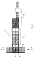
- Figure 1 shows a device 1 for removing, layer by layer, objects 3 which are stacked in a plurality of layers on a first carrier 2.
- the first carrier 2 is, for example, a (wooden) pallet which is in widespread use in practice, but may also be any other suitable carrier.
- the first carrier 2 will be referred to throughout as a pallet 2.
- the pallet 2 is standing on a displacement device 4, which is only depicted highly diagrammatically, in order to simplify the illustration.
- the displacement device 4 is designed to move the pallet 2 in a substantially vertical direction. This is indicated in the figure by a double arrow 5.
- the displacement device 4 may, for example, be a lifting device which is provided with hydraulic cylinders for displacing the pallet 2 loaded with objects 3.
- the displacement device 4 may, for example, also comprise a linkage mechanism.
- the device 1 comprises a gripper member 6 which can be used to take hold of at least a top layer 3a of objects 3 from the pallet 2.
- the gripper member 6 is preferably a vacuum suction member.
- a vacuum suction member of this type is provided with a large number of suction openings 8 which are connected to a vacuum source 7 (only highly diagrammatically illustrated) and which can take hold of the top surface of the objects 3 by suction.
- the application of a sufficient suction force to the objects 3 allows the gripper member 6 to take strong enough hold of the objects to be certain that the objects will not easily be able to drop out of the gripper member 6 when the latter is moved downwards. This will be explained in more detail in the text which follows in a discussion of the method according to the invention.
- the gripper member 6 can be moved in a vertical direction by means of a displacement device (not shown in more detail), so that objects of different heights can be processed.
- the top layer of objects 3a is located on a second carrier 9, which is located beneath the gripper member 6 and above the pallet 2 and the layers of objects 3 which are still present thereon.
- the second carrier 9 is located between the gripper member 6 with the layer of objects 3a and the objects 3 which are still present on the pallet 2.
- the device 1 also comprises a conveyor, which is denoted overall by 10 and is designed to convey the objects 3a which have been removed from the second carrier 9 onwards to a device 11 for splitting up the layer of objects 3a, with the compact layer of objects 3a being opened up slightly so that the loose objects 3b no longer bear again one another. Downstream of the device 11, the objects 3b are each moved into the same orientation by an orienting device 12. This can be seen more clearly in Figure 2.
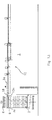
- Figure 2 shows a plan view of the device 1. From a direction denoted by arrow A, loaded pallets 2 are fed to the device 1. Empty pallets are discharged in a direction denoted by arrow B. It is clear from the figure that the gripper member 6 comprises a large number of uniformly distributed suction openings 8. It can also be seen that the objects 3b which have been removed from the pallet 2 and the second carrier 9 are split up and oriented in the devices 11 and 12, respectively.
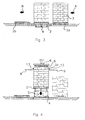
- Figure 3 diagrammatically depicts the step of supplying a pallet 2a loaded with a plurality of layers of objects 3 in the direction A and discharging the empty pallet 2b in the direction B.
- the pallet 2 is resting on the diagrammatically indicated displacement device 4.
- the displacement device 4 which is illustrated in highly diagrammatic form, in the direction of arrow 5 until it reaches a level which is such that the underside of the layer of objects which is to be removed is located just above the level of the second carrier 9.
- Edge-retaining means 13 are arranged at the periphery of the layer of objects 3a.
- the edge-retaining means 13 comprise a plurality of planar plate parts which are designed to clamp the layer of objects 3a in place.
- the gripper member 6 with the suction openings 8 is located above the layer of objects 3a.
- the second carrier 9 preferably comprises two planar plates which are positioned opposite one another and can move in substantially the same place with respect to one another.
- the planar plates together form a planar, continuous plate.
- the two planar plates lie opposite one another, just below the edge-retaining means 13.
- the number of planar plates is not restricted to the number which is shown. The way in which the layer of objects 3a is clamped in place by the edge-retaining means 13 is shown in Figure 5.
- the gripper member 6 is lowered in the direction indicated by arrow 5, as shown in Figure 6.
- the suction openings 8 of the gripper member 6 come into contact with the top surface of the layer of objects 3a and are attached by suction.
- the layer of objects 3a is now clamped in place between the edge-retaining means 13 and the suction openings 8 of the gripper member 6, and the layer of objects 3a can then be removed from the pallet 2 by the first carrier 2 being lowered. This is shown in Figure 7.
- the layer of objects 3a is removed from the pallet 2 as a result of the pallet 2 being moved downwards in the direction indicated by arrow 5.
- the layer of objects 3a in the gripper member 6 is therefore not moved, and therefore no reactive forces are exerted on the objects 3a.
- the lowering of the first carrier 2 produces a space between the underside of the layer of objects 3a in the gripper member 6 and the topside of the next layer of objects 3c down on the pallet 2.
- This space is preferably kept as small as possible, so that the risk of damage in the event of the objects 3a being dropped out of the gripper member 6 is minimized.
- the gripper member 6 is held in a fixed position while the pallet 2 is being moved downwards. As a result, the objects 3a in the gripper member 6 will not move or will scarcely move, and the risk of the objects 3a being dropped is minimized.
- the second carrier 9 is moved into the abovementioned space as a result of the two opposite planar plates being moved towards one another. This is indicated by arrows 14. While the second carrier 9 is being positioned directly below the layer of objects 3a, it is not necessary for the pallet 2 to be moved further downwards, and consequently the pallet 2 only has to be moved to the minimum possible extent. Positioning the second carrier 9 as immediately beneath the layer of objects 3a as possible, i.e. very closely beneath them, means that the gripper member 6 has to be moved downwards scarcely if at all in order for the objects 3a to be placed onto the second carrier 9.
- the fitting of sensors on the second carrier 9 has the advantage that even an object which drops out of the gripper member 6 while the second carrier 9 is being arranged beneath the gripper member 6 can still be detected, and suitable intervention in the movement of the second carrier 9 is then possible.
- the empty gripper member 6 is moved upwards in order not to impede removal of the layer of objects 3a from the second carrier 9. It is clearly apparent from Figure 10 that the conveyor 10 is at the same height as the second carrier 9. Consequently, it is not necessary to adjust the height of the second carrier 9 in order for the objects 3a to be transferred to the conveyor 10. It can be seen in Figure 10 that there is a gap 16 between the second carrier 9 and the conveyor 10, and this gap has to be bridged during the transfer of the objects 3a to the conveyor 10. To bridge this gap 16, the edge-retaining means 13, and in particular the plate part 13a, are designed to be pivotable. This is indicated in Figure 11 with the aid of arrow 17.
- the layer of objects 3a is pushed over the plate part 13a towards the conveyor 10 by a device which is not shown in more detail, for the sake of simplicity of illustration. This operation is shown in Figure 12.
- the plate part 13a of the edge-retaining means 13 is folded upwards again, as indicated by arrow 18, and the second carrier 9 is ready to be removed again from beneath the gripper member 6, and the device 1 can be used once again to remove a subsequent layer of objects 3c from the pallet 2.
- the device 1 has been described in combination with a single conveyor 10. However, it is eminently possible for a plurality of conveyors, extending from one or more of the other sides of the pallet 2, to be employed instead of a single conveyor 10.
- the present invention is described on the basis of the removal of objects which are stacked in a plurality of layers on a carrier, in particular a pallet.
- a carrier in particular a pallet.
- inventive idea can also be applied to the stacking of objects, which are supplied, for example, by a conveyor, on a carrier.
- the invention has been described on the basis of the removal of objects from the first carrier 2 to the conveyor 10.
- the inventive idea of positioning a second carrier between the gripper member and the first carrier ensures that the distance between the objects in the gripper member and the first carrier is very short. As a result, the displacement of the objects in the gripper member is considerably limited and the risk of the objects being damaged is virtually eliminated. Moreover, a high working speed can also be achieved during loading of a pallet, since on the one hand only slight displacement in the vertical direction is required in order to create space for the second carrier, and on the other hand since the objects can be transferred from the conveyor to the second carrier independently of the movement of the gripper member and the first carrier away from one another.
Landscapes
- Engineering & Computer Science (AREA)
- Mechanical Engineering (AREA)
- De-Stacking Of Articles (AREA)
- Stacking Of Articles And Auxiliary Devices (AREA)
Applications Claiming Priority (2)
| Application Number | Priority Date | Filing Date | Title |
|---|---|---|---|
| NL1022628A NL1022628C1 (nl) | 2003-02-07 | 2003-02-07 | Werkwijze en inrichting voor het laagsgewijs verwijderen van voorwerpen van een drager. |
| NL1022628 | 2003-02-07 |
Publications (2)
| Publication Number | Publication Date |
|---|---|
| EP1445220A2 true EP1445220A2 (fr) | 2004-08-11 |
| EP1445220A3 EP1445220A3 (fr) | 2004-09-15 |
Family
ID=32653388
Family Applications (1)
| Application Number | Title | Priority Date | Filing Date |
|---|---|---|---|
| EP04075370A Withdrawn EP1445220A3 (fr) | 2003-02-07 | 2004-02-05 | Méthode et dispositif pour désempiler des articles par couches |
Country Status (2)
| Country | Link |
|---|---|
| EP (1) | EP1445220A3 (fr) |
| NL (1) | NL1022628C1 (fr) |
Cited By (3)
| Publication number | Priority date | Publication date | Assignee | Title |
|---|---|---|---|---|
| WO2012007853A1 (fr) | 2010-07-16 | 2012-01-19 | Bema S.R.L. | Appareil pour manipulation laser de produits palettisés |
| US20150078877A1 (en) * | 2011-12-20 | 2015-03-19 | Ludwig Brandmüller | Depalletizing System and Removal Unit |
| JP2023039104A (ja) * | 2021-09-08 | 2023-03-20 | 株式会社ダイフク | 荷卸し装置 |
Citations (1)
| Publication number | Priority date | Publication date | Assignee | Title |
|---|---|---|---|---|
| DE3117396A1 (de) | 1981-05-02 | 1983-08-11 | Seitz Enzinger Noll Maschinenbau Ag, 6800 Mannheim | "vorrichtung zum schichtweisen be- oder entpalettieren von stueckguetern" |
Family Cites Families (3)
| Publication number | Priority date | Publication date | Assignee | Title |
|---|---|---|---|---|
| US3780884A (en) * | 1972-04-03 | 1973-12-25 | Kenway Eng Inc | Article transfer device |
| US3917082A (en) * | 1972-10-24 | 1975-11-04 | Wyard Ind Inc | Destacking apparatus |
| US4753564A (en) * | 1987-01-23 | 1988-06-28 | Goldco Industries, Inc. | Apparatus and method for effecting movement of selected tiers of stacked articles using pressure differentials |
-
2003
- 2003-02-07 NL NL1022628A patent/NL1022628C1/nl not_active IP Right Cessation
-
2004
- 2004-02-05 EP EP04075370A patent/EP1445220A3/fr not_active Withdrawn
Patent Citations (1)
| Publication number | Priority date | Publication date | Assignee | Title |
|---|---|---|---|---|
| DE3117396A1 (de) | 1981-05-02 | 1983-08-11 | Seitz Enzinger Noll Maschinenbau Ag, 6800 Mannheim | "vorrichtung zum schichtweisen be- oder entpalettieren von stueckguetern" |
Cited By (6)
| Publication number | Priority date | Publication date | Assignee | Title |
|---|---|---|---|---|
| WO2012007853A1 (fr) | 2010-07-16 | 2012-01-19 | Bema S.R.L. | Appareil pour manipulation laser de produits palettisés |
| US10138079B2 (en) | 2010-07-16 | 2018-11-27 | Bema S.R.L. | Appliance for handling layers of palletized products |
| US20150078877A1 (en) * | 2011-12-20 | 2015-03-19 | Ludwig Brandmüller | Depalletizing System and Removal Unit |
| US9481530B2 (en) * | 2011-12-20 | 2016-11-01 | Ludwig Brandmüller | Depalletizing system and removal unit |
| JP2023039104A (ja) * | 2021-09-08 | 2023-03-20 | 株式会社ダイフク | 荷卸し装置 |
| JP7505463B2 (ja) | 2021-09-08 | 2024-06-25 | 株式会社ダイフク | 荷卸し装置 |
Also Published As
| Publication number | Publication date |
|---|---|
| NL1022628C1 (nl) | 2004-08-10 |
| EP1445220A3 (fr) | 2004-09-15 |
Similar Documents
| Publication | Publication Date | Title |
|---|---|---|
| US4787810A (en) | Method and apparatus for handling stacks of loose sheet material | |
| US8763785B2 (en) | System and method for unloading trays | |
| US4536118A (en) | Apparatus for palletizing pressings | |
| CN107244561B (zh) | 一种全自动焊条装盘堆垛设备 | |
| EP0780172A2 (fr) | Procédé et dispositif pour le chargement et le déchargement automatique d'une pièce de tÔle | |
| CN117340601B (zh) | 产品自动组装设备 | |
| CN216072155U (zh) | 工件转换载具设备 | |
| US5088877A (en) | Bottom support grasping device | |
| US10138078B2 (en) | De-stacking device for de-stacking layers of transport pallets with or without intermediary layers | |
| CN116281797A (zh) | 用于芯片清洗的托盘加盖和拆盖输送系统 | |
| CN114641854B (zh) | 用于基板料盒的装卸装置、基板料盒系统 | |
| EP1445220A2 (fr) | Méthode et dispositif pour désempiler des articles par couches | |
| JPH10218120A (ja) | 果菜類の移載装置 | |
| JP7702021B2 (ja) | ハンド装置、物品移送装置および物品取出方法 | |
| US20260048938A1 (en) | Sorting device | |
| JP2715856B2 (ja) | ピッキング装置 | |
| FR2511217A1 (fr) | Installation automatique de chargement et dechargement d'outillages pour une presse a etages multiples, notamment une presse a stratifier des circuits imprimes multicouches | |
| CN215100712U (zh) | 一种激光切割摆盘机tray盘上下料组件 | |
| EP1505017A1 (fr) | Procédé et dispositif de former et de saisir des paquets de feuilles | |
| US20240367926A1 (en) | Receiving device for transporting objects and combination of such a receiving device with an auxiliary device | |
| CN220054311U (zh) | 一种自动成品摆盘机 | |
| WO1999047439A1 (fr) | Palettiseur perfectionne | |
| EP4349746A1 (fr) | Dispositif d'alimentation de plateaux | |
| JP7643237B2 (ja) | ワークの供給装置 | |
| JP6765135B2 (ja) | 段積み装置 |
Legal Events
| Date | Code | Title | Description |
|---|---|---|---|
| PUAI | Public reference made under article 153(3) epc to a published international application that has entered the european phase |
Free format text: ORIGINAL CODE: 0009012 |
|
| PUAL | Search report despatched |
Free format text: ORIGINAL CODE: 0009013 |
|
| AK | Designated contracting states |
Kind code of ref document: A2 Designated state(s): AT BE BG CH CY CZ DE DK EE ES FI FR GB GR HU IE IT LI LU MC NL PT RO SE SI SK TR |
|
| AX | Request for extension of the european patent |
Extension state: AL LT LV MK |
|
| AK | Designated contracting states |
Kind code of ref document: A3 Designated state(s): AT BE BG CH CY CZ DE DK EE ES FI FR GB GR HU IE IT LI LU MC NL PT RO SE SI SK TR |
|
| AX | Request for extension of the european patent |
Extension state: AL LT LV MK |
|
| AKX | Designation fees paid | ||
| REG | Reference to a national code |
Ref country code: DE Ref legal event code: 8566 |
|
| STAA | Information on the status of an ep patent application or granted ep patent |
Free format text: STATUS: THE APPLICATION IS DEEMED TO BE WITHDRAWN |
|
| 18D | Application deemed to be withdrawn |
Effective date: 20050316 |