EP1445221A1 - Dispositif et procédé pour changer des palettes - Google Patents
Dispositif et procédé pour changer des palettes Download PDFInfo
- Publication number
- EP1445221A1 EP1445221A1 EP04002815A EP04002815A EP1445221A1 EP 1445221 A1 EP1445221 A1 EP 1445221A1 EP 04002815 A EP04002815 A EP 04002815A EP 04002815 A EP04002815 A EP 04002815A EP 1445221 A1 EP1445221 A1 EP 1445221A1
- Authority
- EP
- European Patent Office
- Prior art keywords
- pallet
- transfer carriage
- area
- empty
- transfer
- Prior art date
- Legal status (The legal status is an assumption and is not a legal conclusion. Google has not performed a legal analysis and makes no representation as to the accuracy of the status listed.)
- Granted
Links
- 238000000034 method Methods 0.000 title claims abstract description 33
- 238000012546 transfer Methods 0.000 claims abstract description 154
- 230000008569 process Effects 0.000 description 22
- 238000004806 packaging method and process Methods 0.000 description 20
- 230000032258 transport Effects 0.000 description 5
- 238000009434 installation Methods 0.000 description 2
- 238000004519 manufacturing process Methods 0.000 description 2
- 238000013459 approach Methods 0.000 description 1
- 230000008901 benefit Effects 0.000 description 1
- 230000008859 change Effects 0.000 description 1
- 230000005484 gravity Effects 0.000 description 1
- 238000012423 maintenance Methods 0.000 description 1
- 238000012856 packing Methods 0.000 description 1
- 230000009467 reduction Effects 0.000 description 1
Images







Classifications
-
- B—PERFORMING OPERATIONS; TRANSPORTING
- B65—CONVEYING; PACKING; STORING; HANDLING THIN OR FILAMENTARY MATERIAL
- B65G—TRANSPORT OR STORAGE DEVICES, e.g. CONVEYORS FOR LOADING OR TIPPING, SHOP CONVEYOR SYSTEMS OR PNEUMATIC TUBE CONVEYORS
- B65G57/00—Stacking of articles
-
- B—PERFORMING OPERATIONS; TRANSPORTING
- B65—CONVEYING; PACKING; STORING; HANDLING THIN OR FILAMENTARY MATERIAL
- B65G—TRANSPORT OR STORAGE DEVICES, e.g. CONVEYORS FOR LOADING OR TIPPING, SHOP CONVEYOR SYSTEMS OR PNEUMATIC TUBE CONVEYORS
- B65G1/00—Storing articles, individually or in orderly arrangement, in warehouses or magazines
-
- B—PERFORMING OPERATIONS; TRANSPORTING
- B65—CONVEYING; PACKING; STORING; HANDLING THIN OR FILAMENTARY MATERIAL
- B65G—TRANSPORT OR STORAGE DEVICES, e.g. CONVEYORS FOR LOADING OR TIPPING, SHOP CONVEYOR SYSTEMS OR PNEUMATIC TUBE CONVEYORS
- B65G61/00—Use of pick-up or transfer devices or of manipulators for stacking or de-stacking articles not otherwise provided for
Definitions
- the present invention relates to a device for changing pallets in an automatic palletizer for arranging objects on the pallets, an automatic palletizer with such a device and a method for changing the pallets in the palletizing machine.
- Objects to be arranged can in particular be within the meaning of the invention for envelopes, hygiene products packed in boxes or other containers, such as diapers, sanitary napkins, paper handkerchiefs and the like, as well as labels for bottles.
- devices for changing the pallets which the loaded Pallet using fixed, conventional roller and / or chain conveyors transported from the loading point to a pick-up point, from which, for example can be picked up with the help of a forklift. Furthermore is in the known devices, a feed location is provided, from which likewise using permanently installed, conventional roller and / or chain conveyors an empty pallet can be transported to the loading place.
- the known devices with the roller and / or chain conveyors Changing the pallets has two major disadvantages. Claim on the one hand they take up a fair amount of space since the roller and / or chain conveyors both at the feed point as well as at the loading point as well as at the pick-up point installed must be provided. This leads to space problems in particular, when the space behind the envelope making machine is limited and / or several envelope making machines are placed side by side and the passage between the machines is only chosen as wide should be that operating and maintenance work on the Machine can be made.
- the required width of the Passage is usually smaller than the width to be provided if a pick-up point or a feed point between two adjacent machines conventional roller and / or chain conveyor technology is arranged.
- the palletizing process be interrupted in an undesirable manner for a relatively long time, namely on the one hand for transporting the full pallet from the loading place to the pick-up place and on the other hand for the subsequent transport of the empty pallet from the feed place to the loading place.
- a device for changing pallets with a Movable transfer car proposed that in a first pallet area pick up a first pallet and a second pallet in a second pallet area can.
- the second pallet area the transfer carriage in its first position at a loading point of the palletizing machine.
- Can on a pallet located in the second pallet area hence the objects to be palletized, preferably with the aid of a palletizing robot are arranged or stacked.
- the transfer car procedure in its second position is the first pallet area with the empty pallet at the loading place, while the one in the second pallet area full pallet to a pick-up point from where it is for example picked up with the help of a forklift for further loading can be.
- the transfer carriage preferably has a drive-less pallet relative movement means on, which makes it possible to move the transfer car under one to the environment stationary pallet preferably without significant friction through move although the pallet is still on the transfer trolley or carried by it, i.e. is in contact with the transfer car.
- the pallet relative means of movement extends over both the first pallet area as well as over the second pallet area and can be endless around pulleys be stored all around the transfer car.
- the pallet relative movement means from one or more slide rails to form, which are attached to the transfer car. Such slide rails can easily slide along the bottom of a pallet in contact with it.
- the Pallet relative movement means in particular enables the transfer car after picking up the full pallet from the pick-up place from its second position to move back to its first position without the at the loading place, i.e. in the second position of the transfer carriage in the first pallet area, move the pallet relative to its surroundings. This enables the Load the pallet on the loading place with the objects to be palletized while the transfer car is driving underneath her and at the same time touches or carries and supports.
- the advantage is achieved that the pick-up location for picking up the full pallet provided outside a frame of the automatic palletizer can be, and without permanent presence and therefore permanent Space-consuming roller and / or chain conveyors as in the prior art To have to provide technology.
- the second pallet area carrying the full pallet of the transfer vehicle simply drives in the manner of a cantilever arm out of the frame of the automatic palletizer to one for this provided space, which acts only temporarily as a collection point.
- To the pick-up point is the return of the transfer vehicle to its first position again completely free and can be used for other purposes, for example as a passage between two adjacent machines, i.e. as other traffic area that is not due to protruding parts from the ground the device of the invention in its uses is restricted.
- the endlessly rotating pallet relative movement means can be preferred around one or more roller chains, in particular multiple roller chains, act. A large number of rollers can be rotated in chains of this type stored between the links of two link chains.
- Pallet relative moving means such as in the form of endless Deflecting rollers encircling belts made of suitable plastic and / or rubber or in the form of a little protruding from the surface of the transfer car Rollers that are rotatably mounted.
- the transfer carriage can move during its movement between the first position and the second position by a guide device be performed.
- This preferably has at least two guide rails engage in the guide rollers rotatably mounted on the transfer carriage.
- the guide rails on the transfer carriage and the guide rollers engaging in these stationary on a frame can be rotatably supported.
- One or more wheels are preferably in the middle Area of the transfer carriage arranged and by means of the drive device motor-driven. If necessary, the preferably self-supporting, second pallet area the transfer carriage is supported with one or more support wheels become.
- a third position of the transfer carriage is provided with the pallet magazine, in which the objects to be palletized on one in the second pallet area located pallet can be arranged. In this third position the first pallet area of the transfer vehicle is not with an empty pallet loadable. This requires moving to the first position of the transfer vehicle.
- FIG. 1 are two packaging machines 16 and two according to the invention Automatic palletizers 17 with devices according to the invention for changing pallets. Furthermore, the rear ends 18 of two envelope making machines, not shown, which can be seen Connect right to Fig. 1. That of the envelope making machines Manufactured envelopes are stacked at the ends of the machine 18 fed to the respective packaging machine 16, which in the stack of envelopes Packing boxes packed.
- the packaging boxes filled with finished envelopes act in the exemplary embodiment shown as to be palletized Objects in the sense of the present invention. They are each on a conveyor belt 19 is laid, which feeds them to the respective palletizing machine 17.
- the automatic palletizers 17 each include, in addition to a palletizing robot, the Packaging cartons from the respective conveyor belt 19 and on a Pallet stacks, the device according to the invention for changing pallets according to Figures 2 to 4.
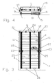
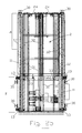
- Fig. 2 shows a side view of the invention Device as essentially results when one in FIG. 1 looks from the left onto the lower palletizing machine 17 there.
- the automatic palletizer 17 has a frame 15, within which in Fig. 2 the transfer car 2 is located.
- the Transfer carriage 2 in two guide rails 11 one in the embodiment shown in supervision essentially U-shaped frame 12 linearly movable stored, with laterally attached to the transfer carriage 2 rotatably Guide rollers 13 in the guide rails which essentially have a U cross section 11 intervene.
- An electric motor 5 attached to the underside of the transfer carriage 2 serves as a drive device for driving two wheels 9 of the transfer car 2, the guided in rails 10 and can best be seen in FIGS. 2 and 4.
- the transfer carriage 2 can be made from one in the figures 1 shown below, 2 and 3, the first position can be moved into a second position, that shown in connection with the upper palletizing machine 17 in FIG. 1 is.
- the transfer carriage 2 moved to the second position he is in Fig. 2 to the right or in Fig. 3 down.
- the transfer carriage 2 is in the first position about half its length retracted into the guide rails 11.
- the transfer carriage is in the second position 2 almost completely extended from the guide rails 11, wherein he however, still in the right in FIG. 2 or in FIG. 3 lower ends of the guide rails 11 is supported to prevent tipping about the axis of the wheels 9, 2 and 3 essentially in the middle of the Transfer carriage 2 are arranged.
- a feed point A, a loading point B and a removal point C lying outside the frame 15 are identified.
- An empty pallet 1 can be fed to the feed station A according to the arrows P A in FIG. 1, for example with the aid of a forklift or pedestrian stacker 20.
- a pallet located there can be loaded with the packaging cartons using the palletizing robot.
- a fully loaded pallet can be picked up from the removal point C according to the arrows P C in FIG. 1 for the purpose of further transport when the transfer carriage 2 is in its second position, as shown in FIG. 1 above.
- the transfer carriage 2 is in its first position, in which it is arranged entirely within the outline of the frame 15 of the automatic palletizer 17.
- the pick-up location C is indicated by dashed lines in FIG. 1, which is only temporarily approached by the transfer car 2, ie by its second pallet area 4, according to the double arrow P T in FIG. 1.
- the pick-up location C is therefore always outside the frame 15 of the automatic palletizing device 17 and thus does not form a spatial component of the device according to the invention. It only has to be available as a space at the installation site of the device in order to be used there temporarily within the scope of the intended use of the device according to the invention.
- loading point B and pick-up point C are according to the invention
- Two preferably angled stops 21 are used as positioning aids an empty pallet at feed location A on frame 12 attached.
- two pads 22 are also one as positioning aids empty pallet attached to the feed location A on the frame 12.
- Two in Fig. 2 from left to right and in Fig. 3 from top to bottom traversable on one side Stops 23 are on the frame 12 for positioning a pallet attached to loading place B, without using a pallet magazine are preferably spring-operated and using a pallet magazine preferably operated externally.
- Stops 24 are for taking an empty pallet from the feed station A. attached to the loading area B on the transfer car 2. Furthermore, there are two in Fig. 2 from left to right or in Fig. 3 from top to bottom traversable on one side Stops 25 for fixing a pallet at loading place B and attached to the pick-up point C on the transfer car 2. After all, there are two immovable, rigid stops 26 for fixing a pallet at the loading place B and attached to the pick-up point C on the transfer car 2. If necessary it is also possible to arrange only one stop or one pad at a time.
- the transfer carriage 2 then moves back to its first position, wherein the stop 23 holds the empty pallet 1 stationary at the loading place B. and the stop 25 is run over.
- the the envelopes Containing packaging boxes 27 are pre-programmed Stacking scheme arranged on the pallet 1.
- An empty pallet 1 ' can either before loading the pallet 1 or after a short interruption of the Palletizing process on the first pallet area located at the feed location A. 3 of the transfer car 2 are placed.
- the transfer car moves 2 in FIG. 9 in its second position, the stop 23 of the Run over empty pallet 1 'and transport full pallet 1 to pick-up point C. becomes.
- the full range is simultaneously 1 from the loading place B and the empty pallet 1 'at the loading place B positioned.
- Fig. 9 it can be clearly seen that the right half of the transfer carriage 2 in the manner of a cantilever arm from the frame 15 protrudes. This is particularly advantageous in terms of occupational safety, there is a foot of an operator who is in the immediate vicinity of the pick-up area C, cannot be run over. It is also advantageous that underneath the transfer carriage 2 there is an optimally free space for movement Industrial truck is created.
- the full pallet 1 can now be picked up from the pick-up location C. and an empty pallet 1 "with the help of the stop 21 and the support 22 on the Feed location A can be positioned. It does not matter whether picking up first full pallet 1 or adding empty pallet 1 " Reloading the empty pallet 1 "an engagement in the from the rack 15th delimited space in which the palletizing robot moves is to A short interruption of the palletizing process is required.
- the transfer carriage 2 according to FIG. 12 is again in its first position driven, the stop 23 holds the pallet 1 'stationary at the loading place B. and the stop 24 is run over by the empty pallet 1 " the transfer carriage 2 into the first position shown in FIG. 12 can be without The palletizing process of pallet 1 'is interrupted.
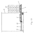
- the transfer carriage 2 is moved in accordance with Fig. 13 moved back to its second position, the stop 23 of the pallet 1 "is run over.
- the now full pallet 1 ' is from the loading place B transported to the pick-up point C while at the same time opening the empty pallet 1 " the loading place B is positioned.
- the full range 1 ' can be temporary by the second pallet area 4 of the transfer carriage 2 Collection point C can be picked up. Then the pallet changing process starting from the stage shown in Fig. 10 again and again performed again.
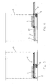
- FIG. 14 to 23 illustrate the sequence when changing pallets with a Device according to the invention, which empty a pallet magazine for storing Has pallets.
- a stack of empty pallets is first placed on the feed station A stored and raised with the help of the pallet magazine 14.
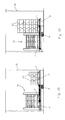
- the transfer carriage 2 is moved into its first position according to FIG. 15 driven in which his first pallet area 3 can be loaded with an empty pallet 1 is that was previously isolated within the pallet magazine 14.
- the transfer carriage 2 is moved into its second position according to FIG. 16 driven, the pallet 1 using the stop 24 to the loading place B is carried along and the stop 23 is run over by it.
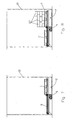
- the transfer carriage 2 is moved into the third position shown in FIG. 17, wherein the stop 23 holds the pallet 1 stationary at the loading place B and the stop 25 is run over.
- the one in the left in FIG Half of the transfer carriage 2 lying first pallet area 3 not from that Pallet magazine 14 are loaded with an empty pallet. This is because that the pallet magazine 14 is spaced sufficiently far from the loading place B. 17, so that the palletizing robot can remove the pallet 1 from the one on the left in FIG Side of loading area B can approach.
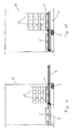
- the transfer carriage 2 according to FIG. 20 is moved from its shown in FIG. first position moved into its second position, the stop 23rd is run over by both the pallet 1 and the pallet 1 '. Doing so on the one hand transports the full pallet 1 to the collection point C and on the other hand the empty pallet 1 'placed on loading place B. Now, according to FIG. 21 started loading the pallet 1 'with packaging boxes 27, one another, empty pallet can be separated in the pallet magazine 14.
- the full pallet 1 is then from the pick-up place C picked up during the palletizing process of those located at loading place B. Pallet 1 'continues.
- the transfer car 2 will also be during of the palletizing process of the pallet 1 'from its second one shown in FIG Position moved into the third position shown in Fig. 23, the stop 23 holds the pallet 1 'stationary at the loading place B and run over the stop 24 becomes. Then the pallet changing process is started with the in Fig. 19 shown stage again and again.
- the inventive Method in connection with the device according to the invention without Pallet magazine can be carried out in such a way that arranging the empty pallet in the first pallet area of the transfer trolley during palletizing the pallet located in the second pallet area takes place, the palletizing process only has to be interrupted briefly.
- the empty pallet in the first pallet area when in use the device according to the invention with pallet magazine only after palletizing the pallet located in the second pallet area because the empty Pallet after completion of palletizing only as shown in Fig. 19 must be picked up from the pallet magazine.
- the stop 24 shows a plan view of a further embodiment of the invention Device similar to the supervision according to FIG. 3.
- the stop 24 is a stop that cannot be driven over and is firmly attached to the transfer carriage 2.
- this fixed stop 24 lifts the empty pallet 1 "a little.
- the stop 21 and the support 22 at least two elongated supports, in particular tubes 28, recognizable in FIG. 24, are provided, which are attached to the frame 12 and at least with their tops across the plane spanned by the multiple roller chains 6 protrude upwards.
- An empty pallet can thus be placed in the feed location A in the first pallet area 3 of the transfer carriage 2 placed on the tubes 28 become.
- the stop 23 can be omitted since the end faces 29 24 the lower ends of the carrier, in particular tubes 28, as fixed stops can function to position a pallet at loading place B.
- the tubes 28 can be extended or extended at their lower ends in FIG. 24 can be shortened by adding relatively short pipe sections as required End inserted or screwed or removed from these ends.
- the stops 25 provided on the transfer carriage 2 were at the in Fig. 24 embodiment shown omitted without replacement. If necessary, the stops 25 but by limiting the range of motion of the Multiple roller chains 6 to be replaced.
- the possibility of movement can limited or blocked in such a way freely movable multiple roller chains 6 that one in the second pallet area 4 on the transfer carriage 2 24 pallet located in Fig. 24 do not leave down can.
- a corresponding limitation of the possibility of movement of the multiple roller chains 6 can be effected, for example, by means of freewheels which are connected to the Interacting pulleys 7 and 8.
- FIG. 25 shows a plan view of yet another embodiment of the invention Device similar to the views according to FIGS. 3 and 24. Same Reference numerals in Fig. 25 denote the same parts as in the embodiments 3 and 24.
- the transfer carriage 2 shown in FIG. 25 is for operation with a pallet magazine provided as described with reference to FIGS. 14 to 23. deviant extends from the previously described embodiments the frame 12 substantially over the entire length of the transfer carriage 2.
- the frame 12 is by means of a total of six feet 30 on the floor of the installation site attached or supported.
- the entire frame 12 is located 25 within the frame frame 15 (not shown in FIG. 2 (see FIG. 2 and 14 to 23). Feed point A or loading point B is on the left Fig. 25 marked.
- the provided for driving the transfer carriage 2 electric motor 5 is not on the Transfer car 2 attached itself, but is stationary below the level, in which the pallets come to rest at loading place B.
- the transfer the drive movement from the electric motor 5 to the transfer carriage 2 takes place with the aid of a drive belt, not shown in FIG Transfer carriage 2 is clamped.
- the rotatably mounted guide rollers 13 not on the transfer carriage 2, but on the stationary frame 12 attached. Accordingly, they are preferably U-shaped Guide rails 11 not on the frame 12, but on the Transfer car 2 arranged so that they move with the latter.
- a driveless pallet relative movement means in the sense of the present invention are a total of six slide strips in the embodiment according to FIG. 25 31 provided, which are attached to the transfer carriage 2 and consequently with move this. Multiple roller chains as in the previous embodiments are therefore not available.
- Fig. 25 are further a total three stop slide rails 32 can be seen, each between two slide rails 31 arranged and attached to the frame 12 so that they are not move with the transfer car 2.
- the stationary stop slide rails 32 do not extend over the entire length of the frame 12 or transfer car 2, but end with their end faces 33 where the loading place B begins, as can be seen in FIG.
- the stop slide rails 32 protrude 25 a little beyond the plane that of the surfaces of the slide strips 31 is formed.
- the embodiment has 25 no fixed stops for taking an empty pallet from the feed point A to the loading point B, but pivotally mounted Stops 24. These stops 24 are when approaching the feed location A mechanically lifted mechanically and fold when Return from loading point B towards feed point A due to gravity down away. This means that a empty pallet can be easily passed under.
- the centering or positioning a pallet to be loaded at loading place B is done by driving back of the transfer carriage 2 in the direction of the feed location A and the resultant Stop the pallet to be loaded on the end faces 33 of the stop slide rails 32nd
- the loading area A is not loaded by means of a pallet magazine, then can the fed pallet at the feed location A in the direction transverse to the longitudinal direction the transfer carriage 2 by means of a suitable stop at the feed station A centered or positioned.
- the stop slide strips 32 can at least in the area of the feed station A by rails at an angle to the longitudinal direction of the transfer carriage 2 standing rollers are replaced so that the pallet during movement in the direction of loading area B across the longitudinal direction of the transfer carriage 2 centered or positioned.
Landscapes
- Engineering & Computer Science (AREA)
- Mechanical Engineering (AREA)
- Intermediate Stations On Conveyors (AREA)
- Stacking Of Articles And Auxiliary Devices (AREA)
Priority Applications (1)
| Application Number | Priority Date | Filing Date | Title |
|---|---|---|---|
| US10/992,237 US7559738B2 (en) | 2004-02-09 | 2004-11-18 | Device and a method for switching pallets |
Applications Claiming Priority (2)
| Application Number | Priority Date | Filing Date | Title |
|---|---|---|---|
| DE10305095A DE10305095A1 (de) | 2003-02-07 | 2003-02-07 | Vorrichtung und Verfahren zum Wechseln von Paletten in einem Palettierautomaten |
| DE10305095 | 2003-02-07 |
Publications (2)
| Publication Number | Publication Date |
|---|---|
| EP1445221A1 true EP1445221A1 (fr) | 2004-08-11 |
| EP1445221B1 EP1445221B1 (fr) | 2005-09-14 |
Family
ID=32603198
Family Applications (1)
| Application Number | Title | Priority Date | Filing Date |
|---|---|---|---|
| EP04002815A Expired - Lifetime EP1445221B1 (fr) | 2003-02-07 | 2004-02-09 | Dispositif et procédé pour changer des palettes |
Country Status (3)
| Country | Link |
|---|---|
| EP (1) | EP1445221B1 (fr) |
| AT (1) | ATE304505T1 (fr) |
| DE (2) | DE10305095A1 (fr) |
Cited By (3)
| Publication number | Priority date | Publication date | Assignee | Title |
|---|---|---|---|---|
| FR2921636A1 (fr) * | 2007-09-28 | 2009-04-03 | Sidel Participations | Installation de palettisation securisee |
| DE102017113181A1 (de) * | 2017-06-14 | 2018-12-20 | Haver & Boecker Ohg | Ladekopf und Verfahren zum Umladen von Ladungseinheiten |
| CN115027865A (zh) * | 2022-07-21 | 2022-09-09 | 联宝(合肥)电子科技有限公司 | 上料设备及自动补料接料生产系统 |
Families Citing this family (2)
| Publication number | Priority date | Publication date | Assignee | Title |
|---|---|---|---|---|
| DE102006024900A1 (de) * | 2006-05-24 | 2007-11-29 | WINKLER + DüNNEBIER AG | Vorrichtung und Verfahren zum Handhaben von Paletten in- und außerhalb einer Palettierzelle |
| DE102012203575A1 (de) | 2012-03-07 | 2013-09-12 | Krones Ag | Fahrerloses Transportsystem einer Fertigungs- und/oder Verpackungsanlage und Verfahren zu deren Steuerung |
Citations (6)
| Publication number | Priority date | Publication date | Assignee | Title |
|---|---|---|---|---|
| US3645409A (en) * | 1970-03-09 | 1972-02-29 | Anderson Clayton & Co | Load transfer and pallet stacker |
| FR2207076A1 (fr) * | 1972-11-21 | 1974-06-14 | Ribes Rene | |
| US3836018A (en) * | 1971-12-13 | 1974-09-17 | Alvey Inc | Discrete article palletizing and depalletizing apparatus |
| DE3417736A1 (de) * | 1984-05-12 | 1985-11-14 | Möllers Maschinenfabrik GmbH, 4720 Beckum | Einrichtung zum kommissionieren von auf paletten bereitgestellten stueckguetern |
| US4850783A (en) * | 1984-12-01 | 1989-07-25 | Murata Kikai Kabushiki Kaisha | Palletizing system for articles |
| US6340282B1 (en) * | 1998-02-10 | 2002-01-22 | Arthur Bar Gmbh | Handling device for feeding and/or removing workpieces |
Family Cites Families (3)
| Publication number | Priority date | Publication date | Assignee | Title |
|---|---|---|---|---|
| US4419035A (en) * | 1982-04-21 | 1983-12-06 | Stobb, Inc. | Method and apparatus for moving bundles of sheets |
| ES2024768A6 (es) * | 1990-04-27 | 1992-03-01 | Villanueva Herrando Eliseo | Disposicion para transferencia de cargas. |
| DE20012197U1 (de) * | 2000-07-14 | 2001-01-04 | viastore systems GmbH, 70469 Stuttgart | Lastaufnahmevorrichtung |
-
2003
- 2003-02-07 DE DE10305095A patent/DE10305095A1/de not_active Withdrawn
-
2004
- 2004-02-09 AT AT04002815T patent/ATE304505T1/de not_active IP Right Cessation
- 2004-02-09 DE DE502004000061T patent/DE502004000061D1/de not_active Expired - Lifetime
- 2004-02-09 EP EP04002815A patent/EP1445221B1/fr not_active Expired - Lifetime
Patent Citations (6)
| Publication number | Priority date | Publication date | Assignee | Title |
|---|---|---|---|---|
| US3645409A (en) * | 1970-03-09 | 1972-02-29 | Anderson Clayton & Co | Load transfer and pallet stacker |
| US3836018A (en) * | 1971-12-13 | 1974-09-17 | Alvey Inc | Discrete article palletizing and depalletizing apparatus |
| FR2207076A1 (fr) * | 1972-11-21 | 1974-06-14 | Ribes Rene | |
| DE3417736A1 (de) * | 1984-05-12 | 1985-11-14 | Möllers Maschinenfabrik GmbH, 4720 Beckum | Einrichtung zum kommissionieren von auf paletten bereitgestellten stueckguetern |
| US4850783A (en) * | 1984-12-01 | 1989-07-25 | Murata Kikai Kabushiki Kaisha | Palletizing system for articles |
| US6340282B1 (en) * | 1998-02-10 | 2002-01-22 | Arthur Bar Gmbh | Handling device for feeding and/or removing workpieces |
Cited By (5)
| Publication number | Priority date | Publication date | Assignee | Title |
|---|---|---|---|---|
| FR2921636A1 (fr) * | 2007-09-28 | 2009-04-03 | Sidel Participations | Installation de palettisation securisee |
| WO2009050374A3 (fr) * | 2007-09-28 | 2009-06-11 | Sidel Participations | Installation de palettisation securisee |
| US8371797B2 (en) | 2007-09-28 | 2013-02-12 | Sidel Participations | Secured palletization facility |
| DE102017113181A1 (de) * | 2017-06-14 | 2018-12-20 | Haver & Boecker Ohg | Ladekopf und Verfahren zum Umladen von Ladungseinheiten |
| CN115027865A (zh) * | 2022-07-21 | 2022-09-09 | 联宝(合肥)电子科技有限公司 | 上料设备及自动补料接料生产系统 |
Also Published As
| Publication number | Publication date |
|---|---|
| ATE304505T1 (de) | 2005-09-15 |
| DE502004000061D1 (de) | 2005-10-20 |
| EP1445221B1 (fr) | 2005-09-14 |
| DE10305095A1 (de) | 2004-08-26 |
Similar Documents
| Publication | Publication Date | Title |
|---|---|---|
| DE69418438T2 (de) | Vorrichtung und Verfahren zum Palettieren von instabilen Gegenständen | |
| DE69328391T2 (de) | Aufbewahrungsvorrichtung für Stangen | |
| EP0101837B1 (fr) | Procédé et dispositif pour la palettisation et la dépalettisation de couvercles | |
| DE2537279A1 (de) | Palettenentlader | |
| DE3317765A1 (de) | Vorrichtung zum palettieren von pressteilen | |
| DE2334651A1 (de) | Vorrichtung zum beladen von paletten mit stueckgut | |
| DE2355143C3 (de) | Paletten-Umsetzvorrichtung | |
| DE2357348C3 (de) | Vorrichtung zum Umsetzen von Frachteinheiten | |
| DE2127310A1 (de) | Fördereinrichtung für Packungen | |
| DE102014102165A1 (de) | Vorrichtung und Verfahren zum Umladen von Ladungseinheiten | |
| EP1445221B1 (fr) | Dispositif et procédé pour changer des palettes | |
| EP0329945B1 (fr) | Installation pour amener des ébauches d'emballage à une machine d'emballage | |
| CH620883A5 (en) | Device for stacking drums provided with stacking grooves | |
| DE102011082747B4 (de) | Vorrichtung und Verfahren zum Beladen von Paletten | |
| EP1564160B1 (fr) | Dispositif de stockage d'objets | |
| DE2711677A1 (de) | Be- oder entladevorrichtung fuer paletten | |
| DE2004549A1 (de) | Verladevorrichtung für Säcke | |
| DE4427477A1 (de) | Fördereinrichtung | |
| DE3343732C2 (fr) | ||
| EP1202919B1 (fr) | Unite de commande de rayonnages ainsi que des recipients ou des palettes permettant de stocker respectivement d'enlever lesdites recipients ou palettes dans respectivement hors d'un rayonnage | |
| EP1396449B1 (fr) | Procédé pour trier des rouleaux de papier et dispositif de triage de rouleaux | |
| DE1178784B (de) | Maschine zum UEberfuehren von Frachtstuecken von einem Zufoerderer auf eine Ladepalette an einer Beladestelle | |
| DE4238341A1 (en) | Automatic palleting device for stackable articles - has continuously operating vertical conveyor picking up goods in any plane | |
| AT501493B1 (de) | Vorrichtung zur entnahme und gleichzeitigen sammlung von ausgewählten produktionseinheiten, die in zellen, fächern oder ablagebrettern eines lagers vorliegen | |
| DE3303307A1 (de) | Vorrichtung zum palettieren von behaeltern |
Legal Events
| Date | Code | Title | Description |
|---|---|---|---|
| PUAI | Public reference made under article 153(3) epc to a published international application that has entered the european phase |
Free format text: ORIGINAL CODE: 0009012 |
|
| AK | Designated contracting states |
Kind code of ref document: A1 Designated state(s): AT BE BG CH CY CZ DE DK EE ES FI FR GB GR HU IE IT LI LU MC NL PT RO SE SI SK TR |
|
| AX | Request for extension of the european patent |
Extension state: AL LT LV MK |
|
| 17P | Request for examination filed |
Effective date: 20050118 |
|
| GRAP | Despatch of communication of intention to grant a patent |
Free format text: ORIGINAL CODE: EPIDOSNIGR1 |
|
| AKX | Designation fees paid |
Designated state(s): AT BE BG CH CY CZ DE DK EE ES FI FR GB GR HU IE IT LI LU MC NL PT RO SE SI SK TR |
|
| GRAS | Grant fee paid |
Free format text: ORIGINAL CODE: EPIDOSNIGR3 |
|
| GRAA | (expected) grant |
Free format text: ORIGINAL CODE: 0009210 |
|
| AK | Designated contracting states |
Kind code of ref document: B1 Designated state(s): AT BE BG CH CY CZ DE DK EE ES FI FR GB GR HU IE IT LI LU MC NL PT RO SE SI SK TR |
|
| PG25 | Lapsed in a contracting state [announced via postgrant information from national office to epo] |
Ref country code: IT Free format text: LAPSE BECAUSE OF FAILURE TO SUBMIT A TRANSLATION OF THE DESCRIPTION OR TO PAY THE FEE WITHIN THE PRESCRIBED TIME-LIMIT;WARNING: LAPSES OF ITALIAN PATENTS WITH EFFECTIVE DATE BEFORE 2007 MAY HAVE OCCURRED AT ANY TIME BEFORE 2007. THE CORRECT EFFECTIVE DATE MAY BE DIFFERENT FROM THE ONE RECORDED. Effective date: 20050914 Ref country code: SK Free format text: LAPSE BECAUSE OF FAILURE TO SUBMIT A TRANSLATION OF THE DESCRIPTION OR TO PAY THE FEE WITHIN THE PRESCRIBED TIME-LIMIT Effective date: 20050914 Ref country code: GB Free format text: LAPSE BECAUSE OF FAILURE TO SUBMIT A TRANSLATION OF THE DESCRIPTION OR TO PAY THE FEE WITHIN THE PRESCRIBED TIME-LIMIT Effective date: 20050914 Ref country code: FI Free format text: LAPSE BECAUSE OF FAILURE TO SUBMIT A TRANSLATION OF THE DESCRIPTION OR TO PAY THE FEE WITHIN THE PRESCRIBED TIME-LIMIT Effective date: 20050914 Ref country code: SI Free format text: LAPSE BECAUSE OF FAILURE TO SUBMIT A TRANSLATION OF THE DESCRIPTION OR TO PAY THE FEE WITHIN THE PRESCRIBED TIME-LIMIT Effective date: 20050914 Ref country code: IE Free format text: LAPSE BECAUSE OF FAILURE TO SUBMIT A TRANSLATION OF THE DESCRIPTION OR TO PAY THE FEE WITHIN THE PRESCRIBED TIME-LIMIT Effective date: 20050914 Ref country code: CZ Free format text: LAPSE BECAUSE OF FAILURE TO SUBMIT A TRANSLATION OF THE DESCRIPTION OR TO PAY THE FEE WITHIN THE PRESCRIBED TIME-LIMIT Effective date: 20050914 Ref country code: RO Free format text: LAPSE BECAUSE OF FAILURE TO SUBMIT A TRANSLATION OF THE DESCRIPTION OR TO PAY THE FEE WITHIN THE PRESCRIBED TIME-LIMIT Effective date: 20050914 |
|
| REG | Reference to a national code |
Ref country code: GB Ref legal event code: FG4D Free format text: NOT ENGLISH |
|
| REG | Reference to a national code |
Ref country code: CH Ref legal event code: EP |
|
| REG | Reference to a national code |
Ref country code: IE Ref legal event code: FG4D Free format text: LANGUAGE OF EP DOCUMENT: GERMAN |
|
| REF | Corresponds to: |
Ref document number: 502004000061 Country of ref document: DE Date of ref document: 20051020 Kind code of ref document: P |
|
| PG25 | Lapsed in a contracting state [announced via postgrant information from national office to epo] |
Ref country code: SE Free format text: LAPSE BECAUSE OF FAILURE TO SUBMIT A TRANSLATION OF THE DESCRIPTION OR TO PAY THE FEE WITHIN THE PRESCRIBED TIME-LIMIT Effective date: 20051214 Ref country code: GR Free format text: LAPSE BECAUSE OF FAILURE TO SUBMIT A TRANSLATION OF THE DESCRIPTION OR TO PAY THE FEE WITHIN THE PRESCRIBED TIME-LIMIT Effective date: 20051214 Ref country code: BG Free format text: LAPSE BECAUSE OF FAILURE TO SUBMIT A TRANSLATION OF THE DESCRIPTION OR TO PAY THE FEE WITHIN THE PRESCRIBED TIME-LIMIT Effective date: 20051214 Ref country code: DK Free format text: LAPSE BECAUSE OF FAILURE TO SUBMIT A TRANSLATION OF THE DESCRIPTION OR TO PAY THE FEE WITHIN THE PRESCRIBED TIME-LIMIT Effective date: 20051214 |
|
| PG25 | Lapsed in a contracting state [announced via postgrant information from national office to epo] |
Ref country code: ES Free format text: LAPSE BECAUSE OF FAILURE TO SUBMIT A TRANSLATION OF THE DESCRIPTION OR TO PAY THE FEE WITHIN THE PRESCRIBED TIME-LIMIT Effective date: 20051225 |
|
| PG25 | Lapsed in a contracting state [announced via postgrant information from national office to epo] |
Ref country code: AT Free format text: LAPSE BECAUSE OF NON-PAYMENT OF DUE FEES Effective date: 20060209 |
|
| PG25 | Lapsed in a contracting state [announced via postgrant information from national office to epo] |
Ref country code: PT Free format text: LAPSE BECAUSE OF FAILURE TO SUBMIT A TRANSLATION OF THE DESCRIPTION OR TO PAY THE FEE WITHIN THE PRESCRIBED TIME-LIMIT Effective date: 20060214 |
|
| PG25 | Lapsed in a contracting state [announced via postgrant information from national office to epo] |
Ref country code: LU Free format text: LAPSE BECAUSE OF NON-PAYMENT OF DUE FEES Effective date: 20060228 Ref country code: MC Free format text: LAPSE BECAUSE OF NON-PAYMENT OF DUE FEES Effective date: 20060228 |
|
| PG25 | Lapsed in a contracting state [announced via postgrant information from national office to epo] |
Ref country code: HU Free format text: LAPSE BECAUSE OF FAILURE TO SUBMIT A TRANSLATION OF THE DESCRIPTION OR TO PAY THE FEE WITHIN THE PRESCRIBED TIME-LIMIT Effective date: 20060315 |
|
| GBV | Gb: ep patent (uk) treated as always having been void in accordance with gb section 77(7)/1977 [no translation filed] |
Effective date: 20050914 |
|
| REG | Reference to a national code |
Ref country code: IE Ref legal event code: FD4D |
|
| PLBE | No opposition filed within time limit |
Free format text: ORIGINAL CODE: 0009261 |
|
| STAA | Information on the status of an ep patent application or granted ep patent |
Free format text: STATUS: NO OPPOSITION FILED WITHIN TIME LIMIT |
|
| 26N | No opposition filed |
Effective date: 20060615 |
|
| PG25 | Lapsed in a contracting state [announced via postgrant information from national office to epo] |
Ref country code: FR Free format text: LAPSE BECAUSE OF FAILURE TO SUBMIT A TRANSLATION OF THE DESCRIPTION OR TO PAY THE FEE WITHIN THE PRESCRIBED TIME-LIMIT Effective date: 20061020 |
|
| EN | Fr: translation not filed | ||
| EN | Fr: translation not filed | ||
| PGFP | Annual fee paid to national office [announced via postgrant information from national office to epo] |
Ref country code: BE Payment date: 20070301 Year of fee payment: 4 |
|
| PG25 | Lapsed in a contracting state [announced via postgrant information from national office to epo] |
Ref country code: EE Free format text: LAPSE BECAUSE OF FAILURE TO SUBMIT A TRANSLATION OF THE DESCRIPTION OR TO PAY THE FEE WITHIN THE PRESCRIBED TIME-LIMIT Effective date: 20050914 |
|
| PG25 | Lapsed in a contracting state [announced via postgrant information from national office to epo] |
Ref country code: TR Free format text: LAPSE BECAUSE OF FAILURE TO SUBMIT A TRANSLATION OF THE DESCRIPTION OR TO PAY THE FEE WITHIN THE PRESCRIBED TIME-LIMIT Effective date: 20050914 |
|
| BERE | Be: lapsed |
Owner name: *WINKLER + DUNNEBIER A.G. Effective date: 20080228 |
|
| REG | Reference to a national code |
Ref country code: CH Ref legal event code: PL |
|
| PG25 | Lapsed in a contracting state [announced via postgrant information from national office to epo] |
Ref country code: CH Free format text: LAPSE BECAUSE OF NON-PAYMENT OF DUE FEES Effective date: 20080229 Ref country code: LI Free format text: LAPSE BECAUSE OF NON-PAYMENT OF DUE FEES Effective date: 20080229 |
|
| NLV4 | Nl: lapsed or anulled due to non-payment of the annual fee |
Effective date: 20080901 |
|
| PG25 | Lapsed in a contracting state [announced via postgrant information from national office to epo] |
Ref country code: NL Free format text: LAPSE BECAUSE OF NON-PAYMENT OF DUE FEES Effective date: 20080901 Ref country code: FR Free format text: LAPSE BECAUSE OF FAILURE TO SUBMIT A TRANSLATION OF THE DESCRIPTION OR TO PAY THE FEE WITHIN THE PRESCRIBED TIME-LIMIT Effective date: 20050914 Ref country code: CY Free format text: LAPSE BECAUSE OF FAILURE TO SUBMIT A TRANSLATION OF THE DESCRIPTION OR TO PAY THE FEE WITHIN THE PRESCRIBED TIME-LIMIT Effective date: 20050914 |
|
| PG25 | Lapsed in a contracting state [announced via postgrant information from national office to epo] |
Ref country code: BE Free format text: LAPSE BECAUSE OF NON-PAYMENT OF DUE FEES Effective date: 20080228 |
|
| PGFP | Annual fee paid to national office [announced via postgrant information from national office to epo] |
Ref country code: DE Payment date: 20100423 Year of fee payment: 7 |
|
| REG | Reference to a national code |
Ref country code: DE Ref legal event code: R119 Ref document number: 502004000061 Country of ref document: DE Effective date: 20110901 |
|
| PG25 | Lapsed in a contracting state [announced via postgrant information from national office to epo] |
Ref country code: DE Free format text: LAPSE BECAUSE OF NON-PAYMENT OF DUE FEES Effective date: 20110901 |