EP1445231A2 - Overload detection method and apparatus on bridge cranes - Google Patents
Overload detection method and apparatus on bridge cranes Download PDFInfo
- Publication number
- EP1445231A2 EP1445231A2 EP04002108A EP04002108A EP1445231A2 EP 1445231 A2 EP1445231 A2 EP 1445231A2 EP 04002108 A EP04002108 A EP 04002108A EP 04002108 A EP04002108 A EP 04002108A EP 1445231 A2 EP1445231 A2 EP 1445231A2
- Authority
- EP
- European Patent Office
- Prior art keywords
- load
- crane
- trolley
- incorrect
- recorded
- Prior art date
- Legal status (The legal status is an assumption and is not a legal conclusion. Google has not performed a legal analysis and makes no representation as to the accuracy of the status listed.)
- Withdrawn
Links
Images

Classifications
-
- B—PERFORMING OPERATIONS; TRANSPORTING
- B66—HOISTING; LIFTING; HAULING
- B66C—CRANES; LOAD-ENGAGING ELEMENTS OR DEVICES FOR CRANES, CAPSTANS, WINCHES, OR TACKLES
- B66C15/00—Safety gear
Definitions
- the invention relates to a method and a device for incorrect load detection on a gantry crane, preferably for a pouring or charging crane in the Metallurgy.
- Lifting devices have been developed for lifting loads in rooms that are difficult to access or at risk. Load handling is problematic in cases when the crane operator's visibility is restricted during the lifting process. Such situations usually require instruction from the crane operator in order to rule out dangerous moments when lifting the load and to ensure safe transport. Instruction during the slinging process is usually always associated with the use of an additional worker, which has an adverse effect on the effectiveness of the transport. Particularly in metallurgy, where charging vessels and ladles of various designs are used to transport molten metals, well-functioning, self-supporting lifting devices are necessary to ensure smooth transport of the molten metal between the individual production units. Despite the presence of such load suspension devices, a residual risk cannot be excluded. Incorrect load pick-up can, however, lead to a significant accident with several days of production downtime. In metallurgical plants in particular, the damage can be considerable if a pan with melt liquid is caught on one side and the melt liquid escapes from the vessel.
- the load suspension device is equipped with load suspension elements, which are individually resiliently arranged on the supporting structure of the load suspension device.
- the load suspension devices are attached to bolts which are guided in the vertical direction through elongated holes in the web plates.
- the bolts are spring-loaded and each have a switching flag, which is coupled to a pulse generator. These pulse generators trigger a signal if not all pulse generators emit the same signal or the number of pulse generators does not match the number of signals emitted by the pulse generators.
- Such a solution has the defect that the load suspension device must be designed accordingly in order to install the pulse generator. Furthermore, the arrangement of the sensors in the immediate area of the load, particularly when used in metallurgy, is problematic, since such a solution is extremely susceptible to failure due to the existing loads caused by heat and dust.
- the object of the invention is a method and a device for To develop gantry cranes with under difficult external conditions, such as B. heat and dust, a safe control of Load pickup can be guaranteed and thus the safety when Striking the load and transporting it increases downtime as well Production facilities due to damage from damaged loads be avoided.
- the object is achieved by a method according to claim 1 solved.
- a device for implementing the method is in the claims 2 and 3 described.
- the exemplary embodiment relates to the detection of incorrect loads on a charging crane in a steel mill.
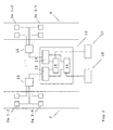
- Such cranes essentially consist of a trolley 2 on which two cable drums 1 for receiving the supporting cables are arranged, to which a crossbar 8 is attached with two load-bearing hooks 9 fastened to it on both sides.
- the trolley 2 consists of a support frame with four wheels 4 arranged at the corner points of the support frame, which can be moved on a carrier A, 7 in FIG. 1, or on a carrier D, marked 6 in FIG. 1.
- the supporting frame of the trolley 2 is supported at its four end points on load cells 3a and 3b, the load cells 3a and 3b being assigned to a load-carrying side.
- load cells 3a 1-4 and 3b 1-4 are located on each of the two load-carrying sides, which are arranged on both sides of an impeller 4 of the trolley 2.
- Crane impellers 5 on the supports A and D enable the trolley 2 to be moved in the longitudinal direction to the charging hall.
- An auxiliary stroke not shown in the drawings, serves to generate the necessary tilting movement during charging.
- the measured value acquisition is initially carried out separately for both sides of the trolley 2 in order to record a possible asymmetrical load on the load cells during load acceptance.
- An asymmetrical load on the load cells occurs when a crane hook 9 is not or not correctly inserted in the support bracket / ladle hanger. The loader then picks up the load on one side.
- the charging pan can be tipped over by an asymmetrical load bearing, which creates a high risk of accidents and considerable malfunctions.
- the invention is also intended to rule out the case where both crane hook tips are located under the two support brackets / pan hangers of a charging pan and thus, although the load is evenly distributed, there is a high risk of the support brackets / pan hangers sliding off the crane hook tips.
- the four load cells 3a 1-4 or 3b 1-4 arranged on the two sides of the trolley 2 are divided into two separate measuring circuits.
- the load cells 3a 1-4 of the load side A are connected to a switch box 10 via measuring lines and the load cells 3b 1-4 of the load side D are connected to a switch box 11.
- a measurement value equivalent to the respective side A or D is formed from the four measurement values of the load cells.
- the two switch boxes 10 and 11 are connected to an evaluation unit 12 for further processing of the measurement signals.
- the evaluation unit 12 consists of a measuring circuit A marked with reference number 13 for determining the weight value of the load side A and a measuring circuit D marked with reference number 14 for determining the weight value of the load side D.
- a differentiator 15 and a summer 16 are arranged in the evaluation unit 12, which are connected in parallel to the two measuring circuits A and D and are connected to them via corresponding cables.
- the load pick-up is a dynamic process, i.e. the weight value changes with the load pick-up depending on the time. Based on this, the change in the weight value of the load-bearing side A is compared with the change in the weight value of the load-bearing side D by the differentiator at the time of the load bearing. The measured value determined from the comparison of the two measurement signals present on the load sides A and D is shown in a subordinate display 17. If the difference exceeds a previously defined amount, there is an incorrect load detection.
- this can also trigger an acoustic signal to warn the personnel.
- the hazard detection of load pick-up on both sides of the crane hook tips was solved by raising one of the two crane hook tips. As a result of this increase, which can be approximately 100 mm in the case of a crane of this type, an unequal change in the weight value when the load is lifted is also indicated when the load is lifted on both sides via the crane hook tips. Safe transport can only take place when the two crane hooks 9 are correctly seated on the support brackets / pan hangers of the charging pan, which is characterized by the same height of the two support points. With the application of the invention, the risk of incorrect load pick-up can be excluded and safe transport can be ensured.
- the summer 16 forms the two applied measurement signals on the load sides A and D by totaling a total that is the total weight which represents the charging pan hanging on the two crane hooks 9.
Landscapes
- Engineering & Computer Science (AREA)
- Mechanical Engineering (AREA)
- Control And Safety Of Cranes (AREA)
Abstract
Die Erfindung betrifft ein Verfahren und eine Einrichtung zur Fehllasterkennung an einem Brückenkran, vorzugsweise für einen Gieß- oder Chargierkran. Aufgabe der Erfindung ist es ein Verfahren und eine Einrichtung zu finden mit der unter schwierigen äußeren Bedingungen, wie z. B. Hitze- und Staubeinwirkungen eine sichere Kontrolle der Lastaufnahme gewährleistet werden kann und dadurch die Sicherheit beim Anschlagen der Last und deren Transport erhöht sowie Ausfallzeiten von Produktionsanlagen infolge von Beschädigungen durch havarierte Lasten vermieden werden. Das Verfahren zur Fehllasterkennung ist dadurch gekennzeichnet, dass die von den Wägezellen (3a1...4,3b1...4) einer Laufkatze (2) ei nes Brückenkranes erfassten Messwerte entsprechend ihrer Zuordnung zu einer der beiden Lastaufnahmeseiten erfasst werden und daraus für jede Seite ein der Belastung äquivalenter Gewichtswert gebildet wird, deren Änderungen während der Lastaufnahme miteinander verglichen werden und bei Überschreitung eines definierten Grenzwertes zu einer Fehllastanzeige führt. <IMAGE>The invention relates to a method and a device for incorrect load detection on a gantry crane, preferably for a casting or charging crane. The object of the invention is to find a method and a device with the under difficult external conditions, such as. B. heat and dust effects a safe control of the load pick-up can be guaranteed, thereby increasing the safety when attaching the load and its transport, and avoiding downtimes in production systems due to damage from damaged loads. The method for incorrect load detection is characterized in that the measured values recorded by the load cells (3a1 ... 4,3b1 ... 4) of a trolley (2) of a bridge crane are recorded in accordance with their assignment to one of the two load-bearing sides and from this for each A weight value equivalent to the load is formed, the changes of which are compared with one another during load acceptance and, when a defined limit value is exceeded, leads to an incorrect load display. <IMAGE>
Description
Die Erfindung betrifft ein Verfahren und eine Einrichtung zur Fehllasterkennung an einem Brückenkran, vorzugsweise für einen Gieß- oder Chargierkran in der Metallurgie.The invention relates to a method and a device for incorrect load detection on a gantry crane, preferably for a pouring or charging crane in the Metallurgy.
Zur Aufnahme von Lasten in schwer zugänglichen oder gefährdeten Räumlichkeiten
sind Lastaufnahmemittel entwickelt worden, welche die Last
selbstständig aufnehmen.
Die Lastaufnahme gestaltet sich dabei in den Fällen problematisch, wenn die
Sichtbedingungen des Kranführers beim Anschlagvorgang eingeschränkt sind.
Derartige Situationen erfordern in der Regel eine Einweisung des Kranführers
um Gefahrenmomente bei der Lastaufnahme auszuschließen und einen sicheren
Transport zu gewährleisten. Die Einweisung beim Anschlagvorgang ist aber in
der Regel immer mit dem Einsatz einer zusätzlichen Arbeitskraft verbunden,
was sich nachteilig auf die Effektivität des Transportes auswirkt. Insbesondere
in der Metallurgie, wo zum Transport von schmelzflüssigen Metallen
Chargiergefäße und Gießpfannen verschiedener Bauart eingesetzt werden, sind
gut funktionierende, selbstständig aufnehmende Lastmittel notwendig, um einen
reibungslosen Transport des schmelzflüssigen Metalls zwischen den einzelnen
Produktionsaggregaten zu gewährleisten. Trotz des Vorhandenseins derartiger
Lastaufnahmemittel kann ein Restrisiko nicht ausgeschlossen werden. Eine
unkorrekte Lastaufnahme kann jedoch zu einem erheblichen Havariefall mit
mehreren Tagen Produktionsausfall führen. Insbesondere in metallurgischen
Betrieben kann der Schaden beträchtlich sein, wenn durch einseitiges Erfassen
einer Pfanne mit Schmelzflüssigkeit es zum Austritt der Schmelzflüssigkeit aus
dem Gefäß kommt. Lifting devices have been developed for lifting loads in rooms that are difficult to access or at risk.
Load handling is problematic in cases when the crane operator's visibility is restricted during the lifting process. Such situations usually require instruction from the crane operator in order to rule out dangerous moments when lifting the load and to ensure safe transport. Instruction during the slinging process is usually always associated with the use of an additional worker, which has an adverse effect on the effectiveness of the transport. Particularly in metallurgy, where charging vessels and ladles of various designs are used to transport molten metals, well-functioning, self-supporting lifting devices are necessary to ensure smooth transport of the molten metal between the individual production units. Despite the presence of such load suspension devices, a residual risk cannot be excluded. Incorrect load pick-up can, however, lead to a significant accident with several days of production downtime. In metallurgical plants in particular, the damage can be considerable if a pan with melt liquid is caught on one side and the melt liquid escapes from the vessel.
Zur Vermeidung derartiger Gefahrensituationen beim Anschlagvorgang von
selbstaufnehmenden Lastaufnahmemitteln ist z. B. eine Vorrichtung zur
Lastaufnahmekontrolle entwickelt worden wie sie in der Veröffentlichung
DD 300 282 beschrieben ist.
Gemäß dieser Lösung ist das Lastaufnahmemittel mit Lastaufnahmeelementen
ausgerüstet, die einzeln federnd an der Tragkonstruktion des Lastaufnahmemittels
angeordnet sind.
Die Lastaufnahmemittel sind an Bolzen befestigt, die in vertikaler Richtung
durch in Stegblechen befindliche Langlöcher geführt werden. Die Bolzen sind
federnd gelagert und mit je einer Schaltfahne versehen, die mit jeweils einem
Impulsgeber gekoppelt ist. Diese Impulsgeber lösen ein Signal aus, wenn nicht
alle Impulsgeber das gleiche Signal abgeben bzw. die Anzahl der Impulsgeber
nicht mit der Anzahl der von den Impulsgebern abgegebenen Signale übereinstimmt.
Eine derartige Lösung hat den Mangel, dass das Lastaufnahmemittel
entsprechend konstruktiv gestaltet sein muss, um die Impulsgeber zu
installieren. Weiterhin ist die Anordnung der Geber im unmittelbaren Bereich
der Last, insbesondere bei einem Einsatz in der Metallurgie, problematisch, da
durch die existierenden Belastungen durch Hitze- und Staubeinwirkung eine
derartige Lösung äußerst störanfällig ist.To avoid such dangerous situations during the striking process of self-receiving lifting devices, e.g. B. a device for load control has been developed as described in the publication DD 300 282.
According to this solution, the load suspension device is equipped with load suspension elements, which are individually resiliently arranged on the supporting structure of the load suspension device.
The load suspension devices are attached to bolts which are guided in the vertical direction through elongated holes in the web plates. The bolts are spring-loaded and each have a switching flag, which is coupled to a pulse generator. These pulse generators trigger a signal if not all pulse generators emit the same signal or the number of pulse generators does not match the number of signals emitted by the pulse generators.
Such a solution has the defect that the load suspension device must be designed accordingly in order to install the pulse generator. Furthermore, the arrangement of the sensors in the immediate area of the load, particularly when used in metallurgy, is problematic, since such a solution is extremely susceptible to failure due to the existing loads caused by heat and dust.
Aufgabe der Erfindung ist es, ein Verfahren und eine Einrichtung für Brückenkrane zu entwickeln, mit der unter schwierigen äußeren Bedingungen, wie z. B. Hitze- und Staubeinwirkungen, eine sichere Kontrolle der Lastaufnahme gewährleistet werden kann und dadurch die Sicherheit beim Anschlagen der Last und deren Transport erhöht sowie Ausfallzeiten von Produktionsanlagen infolge von Beschädigungen durch havarierte Lasten vermieden werden.The object of the invention is a method and a device for To develop gantry cranes with under difficult external conditions, such as B. heat and dust, a safe control of Load pickup can be guaranteed and thus the safety when Striking the load and transporting it increases downtime as well Production facilities due to damage from damaged loads be avoided.
Erfindungsgemäß wird die Aufgabe durch ein Verfahren gemäß Anspruch 1
gelöst. Eine Einrichtung zur Realisierung des Verfahrens ist in den Ansprüchen
2 und 3 beschrieben.According to the invention, the object is achieved by a method according to
Mit dem erfindungsgemäßen Verfahren zur Fehllasterkennung und der dazugehörenden Einrichtung wurde eine Lösung gefunden, mit der das Risiko einer unkorrekten Lastaufnahme beim Einsatz von selbständig aufnehmenden Lastaufnahmemitteln erheblich gemindert werden kann. Der Transport von Lasten kann danach unter Anwendung des beschriebenen Verfahrens sowie der dazu entwickelten Einrichtung sicherer und effektiver gestaltet werden. Insbesondere durch die Vermeidung der Positionierung von weiteren Sensoren an dem Lastaufnahmemittel werden keine zusätzlichen Leitungen oder Kabel benötigt, so dass ein Risiko zu deren Beschädigung im Produktionsprozess, insbesondere bei einem Einsatz in metallurgischen Produktionsprozessen, nicht gegeben ist. Durch die mögliche Nutzung der Messwerte von Wägezellen, die an einem Brückenkran zur Erfassung des Gewichtes der zu transportierenden Last ohnehin angeordnet sind, wird eine weitgehend sichere Fehllasterkennung möglich, die nur geringe Kosten zu deren Installation verursacht. Durch die Gewinnung der für die Fehllasterkennung relevanten Messwerte im Bereich der Laufkatze eines Brückenkranes fallen keine zusätzlichen Wartungsarbeiten an.With the method according to the invention for incorrect load detection and associated facility, a solution was found with which the risk incorrect load handling when using self-supporting Load suspension devices can be significantly reduced. The transport of Loads can then be applied using the described method and the the facility developed for this purpose can be made safer and more effective. In particular by avoiding the positioning of additional sensors there are no additional lines or cables on the load suspension device needed so that there is a risk of damaging them in the production process, especially when used in metallurgical production processes, not given is. Through the possible use of the measured values from load cells, the on a gantry crane to record the weight of the goods to be transported Load are arranged anyway, largely reliable detection of incorrect load possible, which causes only low costs for their installation. Through the Obtaining the measurement values relevant for incorrect load detection in the area of The trolley of a bridge crane does not require any additional maintenance work.
Das erfindungsgemäße Verfahren und die dazugehörende Einrichtung sollen nachfolgend an einem Ausführungsbeispiel näher erläutert werden. In den dazugehörenden Zeichnungen zeigen:
- Fig. 1:
- Laufkatze mit Wägezellen und Lastaufnahmemittel
- Fig. 2:
- Schema der Fehllasterkennung
- Fig. 1:
- Trolley with load cells and load handler
- Fig. 2:
- Misload detection scheme
Das Ausführungsbeispiel bezieht sich auf die Fehllasterkennung an einem
Chargierkran in einem Stahlwerk. Derartige Krane bestehen im wesentlichen aus
einer Laufkatze 2 auf der zwei Seiltrommeln 1 zur Aufnahme der Tragseile
angeordnet sind, an denen eine Traverse 8 mit zwei beidseitig daran befestigten
Lastaufnahmehaken 9 angehängt ist. Die Laufkatze 2 besteht aus einem
Tragrahmen mit vier an den Eckpunkten des Tragrahmens angeordneten
Laufrädern 4, die auf einem Träger A, in Fig. 1 mit 7, bzw. auf einem Träger D,
in Fig. 1 mit 6 gekennzeichnet, verfahrbar sind. Wie aus Fig. 1 weiterhin
ersichtlich ist, lagert der Tragrahmen der Laufkatze 2 an seinen vier Endpunkten
auf Wägezellen 3a bzw. 3b, wobei die Wägezellen 3a bzw. 3b jeweils einer
Lastaufnahmeseite zugeordnet sind. In diesem Beispiel befinden sich auf jeder
der beiden Lastaufnahmeseiten vier Wägezellen 3a1-4 bzw. 3b1-4, die beiderseits
eines Laufrades 4 der Laufkatze 2 angeordnet sind.
Kranlaufräder 5 an den Trägern A und D ermöglichen die Verfahrbarkeit der
Laufkatze 2 in Längsrichtung zur Chargierhalle. Ein in den Zeichnungen nicht
näher dargestellter Hilfshub dient zur Erzeugung der notwendigen Kippbewegung
beim Chargieren.
Erfindungsgemäß erfolgt die Messwerterfassung entgegen der bisherigen Praxis
zunächst für beide Seiten der Laufkatze 2 getrennt, um eine mögliche
unsymmetrische Belastung der Wägezellen bei der Lastaufnahme zu erfassen.
Eine unsymmetrische Belastung der Wägezellen tritt dann auf, wenn ein
Kranhaken 9 nicht oder nicht richtig in der Traglasche / Pfannengehänge
eingesetzt wird. Dann erfolgt eine einseitige Aufnahme der Last durch den
Chargierkran. Dieser Zustand muss unbedingt vermieden werden, da durch eine
unsymmetrische Lastaufnahme die Chargierpfanne zum Kippen gebracht
werden kann, wodurch ein hohes Unfallrisiko entsteht und erhebliche
Betriebsstörungen verursacht werden können. Weiterhin soll mit der Erfindung
auch der Fall ausgeschlossen werden, dass beide Kranhakenspitzen unter den
beiden Traglaschen / Pfannengehänge einer Chargierpfanne stehen und somit,
obwohl eine gleichmäßige Lastaufnahme erfolgt, eine hohe Gefährdung durch
ein Abgleiten der Traglaschen / Pfannengehänge von den Kranhakenspitzen
gegeben ist.
Zur Vermeidung der Gefährdung durch eine unsymmetrische Lastaufnahme sind
die an den beiden Seiten der Laufkatze 2 angeordneten vier Wägezellen 3a1-4
bzw. 3b1-4 auf zwei separate Messkreise aufgeteilt. Die Wägezellen 3a1-4 der
Lastseite A sind über Messleitungen mit einem Schaltkasten 10 und die
Wägezellen 3b1-4 der Lastseite D sind mit einem Schaltkasten 11 verbunden.
In den Schaltkästen 10 und 11 wird ein für die jeweilige Seite A bzw. D
äquivalenter Messwert aus den vier Messwerten der Wägezellen gebildet.
Die beiden Schaltkästen 10 und 11 sind zur weiteren Verarbeitung der
Messsignale mit einer Auswerteeinheit 12 verbunden. Die Auswerteeinheit 12
besteht aus einem mit Bezugsziffer 13 gekennzeichneten Messkreis A zur
Bestimmung des Gewichtswertes der Lastseite A und einem mit Bezugsziffer
14 gekennzeichneten Messkreis D zur Bestimmung des Gewichtswertes der
Lastseite D. Weiterhin sind in der Auswerteeinheit 12 ein Differenzierer 15
sowie ein Summierer 16 angeordnet, die parallel zu den beiden Messkreisen A
und D geschalten und über entsprechende Leitungen mit diesen verbunden sind.
Die Lastaufnahme ist ein dynamischer Vorgang, dass heißt der Gewichtswert
ändert sich bei der Lastaufnahme in Abhängigkeit von der Zeit. Davon
ausgehend wird die Änderung des Gewichtswertes der Lastaufnahmeseite A mit
der Änderung des Gewichtswertes der Lastaufnahmeseite D durch den
Differenzierer zum Zeitpunkt der Lastaufnahme miteinander verglichen.
Der aus dem Vergleich der beiden anliegenden Messsignale der Lastseiten A
und D ermittelte Messwert wird in einer nachgeordneten Anzeige 17 angezeigt.
Überschreitet die Differenz einen vorher definierten Betrag liegt eine
Fehllasterkennung vor. Diese kann neben der optischen Anzeige auch ein
akustisches Signal zu Warnung des Personals auslösen.
Die Gefahrerkennung einer beidseitigen Lastaufnahme auf den Kranhakenspitzen
wurde dadurch gelöst, dass eine der beiden Kranhakenspitzen erhöht ist.
Durch diese Erhöhung, die bei einem derartigen Kran ca. 100 mm betragen
kann, wird bei beidseitiger Lastaufnahme über die Kranhakenspitzen ebenfalls
eine ungleiche Änderung des Gewichtswertes bei der Lastaufnahme angezeigt.
Nur bei richtigem Sitz der beiden Kranhaken 9 an den Traglaschen / Pfannengehänge
der Chargierpfanne, der durch eine gleiche Höhe der beiden
Tragpunkte gekennzeichnet ist, kann ein sicherer Transport erfolgen.
Mit der Anwendung der Erfindung kann die Gefahr einer unkorrekten Lastaufnahme
ausgeschlossen und ein gefahrloser Transport gewährleistet werden.The exemplary embodiment relates to the detection of incorrect loads on a charging crane in a steel mill. Such cranes essentially consist of a
According to the present invention, contrary to previous practice, the measured value acquisition is initially carried out separately for both sides of the
To avoid the danger from an asymmetrical load pick-up, the four
In the
The two
The measured value determined from the comparison of the two measurement signals present on the load sides A and D is shown in a
The hazard detection of load pick-up on both sides of the crane hook tips was solved by raising one of the two crane hook tips. As a result of this increase, which can be approximately 100 mm in the case of a crane of this type, an unequal change in the weight value when the load is lifted is also indicated when the load is lifted on both sides via the crane hook tips. Safe transport can only take place when the two
With the application of the invention, the risk of incorrect load pick-up can be excluded and safe transport can be ensured.
Der Summierer 16 bildet aus den beiden anliegenden Messsignalen der Lastseiten
A und D durch Summenbildung einen Gesamtwert, der das Gesamtgewicht
der der an den beiden Kranhaken 9 hängenden Chargierpfanne darstellt. The
Neben dem vorstehend beschriebenen Ausführungsbeispiel, welches auf der Grundlage einer üblichen Ausgestaltung eines Brückenkranes dargestellt wurde, sind weitere Anwendungsfälle, bei denen z. B. die Wägezellen an der Krantraverse angeordnet sind, denkbar. Wesentlich ist, dass für beide Lastseiten zunächst eine eigene Messwerterfassung durchgeführt werden kann, auf deren Basis infolge einer weiteren Messwertverarbeitung eine Fehllasterkennung sowie eine Erfassung des Gesamtgewichtes möglich ist. In addition to the embodiment described above, which on the The basis of a common design of a gantry crane was presented, are other applications in which, for. B. the load cells on the crane traverse are arranged, conceivable. It is essential that for both load sides You can first carry out your own measured value acquisition, on the basis of which Based on further processing of measured values, incorrect load detection and a determination of the total weight is possible.
- 1:1:
- Seiltrommelcable drum
- 2:2:
- Laufkatzetrolley
- 3a.1-4:3a. 1-4 :
- WägezellenLoad cells
- 3b.1-4:3b. 1-4 :
- WägezellenLoad cells
- 4:4:
- Laufräder KatzeCat wheels
- 5:5:
- Laufräder KranImpeller crane
- 6:6:
- Träger DCarrier D
- 7:7:
- Träger ACarrier A
- 8:8th:
- Traversetraverse
- 9:9:
- Hakenhook
- 10:10:
-
Schaltkasten Träger A
(zur Bildung der Mittelwerte der Wägezellen)Switch box carrier A
(to form the mean values of the load cells) - 11:11:
-
Schaltkasten Träger D
(zur Bildung der Mittelwerte der Wägezellen)Switch box carrier D
(to form the mean values of the load cells) - 12:12:
- Auswerteeinheitevaluation
- 13:13:
- Messkreis A (Bestimmung des Gewichtswert)Measuring circuit A (determination of the weight value)
- 14:14:
- Messkreis D (Bestimmung des Gewichtswert)Measuring circuit D (determination of the weight value)
- 15:15:
- Differenziererdifferentiator
- 16:16:
- Summierersumming
- 17:17:
- Anzeige zur FehllasterkennungDisplay for incorrect load detection
- 18:18:
- Gewichtsanzeige (Wiegedaten)Weight display (weighing data)
Claims (3)
Applications Claiming Priority (2)
| Application Number | Priority Date | Filing Date | Title |
|---|---|---|---|
| DE2003104951 DE10304951A1 (en) | 2003-02-06 | 2003-02-06 | Method and device for incorrect load detection on overhead cranes |
| DE10304951 | 2003-02-06 |
Publications (2)
| Publication Number | Publication Date |
|---|---|
| EP1445231A2 true EP1445231A2 (en) | 2004-08-11 |
| EP1445231A3 EP1445231A3 (en) | 2004-12-22 |
Family
ID=32603188
Family Applications (1)
| Application Number | Title | Priority Date | Filing Date |
|---|---|---|---|
| EP04002108A Withdrawn EP1445231A3 (en) | 2003-02-06 | 2004-01-31 | Overload detection method and apparatus on bridge cranes |
Country Status (2)
| Country | Link |
|---|---|
| EP (1) | EP1445231A3 (en) |
| DE (1) | DE10304951A1 (en) |
Cited By (2)
| Publication number | Priority date | Publication date | Assignee | Title |
|---|---|---|---|---|
| CN102785999A (en) * | 2011-05-16 | 2012-11-21 | 江苏申大衡器有限公司 | Wireless data transmission smart crown block weighing system |
| EP2313336B1 (en) * | 2008-08-20 | 2015-04-01 | Firma Physik-Instrumente Dr. Bernd Brosa GmbH | Early overload detection for a load lifting device |
Families Citing this family (4)
| Publication number | Priority date | Publication date | Assignee | Title |
|---|---|---|---|---|
| DE102012015095A1 (en) | 2012-08-01 | 2014-02-06 | Vdeh-Betriebsforschungsinstitut Gmbh | Hook for crane, has angle measuring unit, which determines displacement of center of gravity of hook in desired position, particularly in perpendicular direction, where angle measuring unit determines deflection from desired position |
| DE102013017803B4 (en) | 2013-10-28 | 2017-01-05 | Vdeh-Betriebsforschungsinstitut Gmbh | "Failure detection system, hoist, crane and misalignment detection method" |
| CN108002231A (en) * | 2017-11-30 | 2018-05-08 | 无锡市汇鼎金属制管有限公司 | A kind of crane weighing device |
| DE102023207474B4 (en) | 2023-08-03 | 2026-01-22 | Fraunhofer-Gesellschaft zur Förderung der angewandten Forschung eingetragener Verein | METHOD FOR VERIFYING AND/OR MONITORING A LOAD HANDLING SYSTEM OF A CRANE AND CRANE COMPLETING A SYSTEM FOR VERIFYING AND/OR MONITORING A LOAD HANDLING SYSTEM OF THE CRANE |
Family Cites Families (2)
| Publication number | Priority date | Publication date | Assignee | Title |
|---|---|---|---|---|
| DE2527411A1 (en) * | 1975-06-20 | 1977-01-13 | Krupp Gmbh | Foundry charging crane gantry - has main crab of U-section with bogie rails clearing gases during charging |
| DE9214417U1 (en) * | 1992-10-24 | 1993-04-15 | Koschinski, Paul, 2070 Ahrensburg | Integrated weighing device for surface-mounted lifting devices (traverses, spreaders) |
-
2003
- 2003-02-06 DE DE2003104951 patent/DE10304951A1/en not_active Withdrawn
-
2004
- 2004-01-31 EP EP04002108A patent/EP1445231A3/en not_active Withdrawn
Cited By (3)
| Publication number | Priority date | Publication date | Assignee | Title |
|---|---|---|---|---|
| EP2313336B1 (en) * | 2008-08-20 | 2015-04-01 | Firma Physik-Instrumente Dr. Bernd Brosa GmbH | Early overload detection for a load lifting device |
| KR101625248B1 (en) | 2008-08-20 | 2016-05-27 | 퍼르마 피직-인스투르먼트 닥터 번드 브로사 게엠베하 | Early overload detection for a load lifting device |
| CN102785999A (en) * | 2011-05-16 | 2012-11-21 | 江苏申大衡器有限公司 | Wireless data transmission smart crown block weighing system |
Also Published As
| Publication number | Publication date |
|---|---|
| EP1445231A3 (en) | 2004-12-22 |
| DE10304951A1 (en) | 2004-08-26 |
Similar Documents
| Publication | Publication Date | Title |
|---|---|---|
| EP2799386B1 (en) | Device and method for determination and monitoring a counterweight which is fitted to a crane | |
| DE60208952T2 (en) | Cranes and methods for controlling the crane | |
| DE102011107754B4 (en) | Angle-related procedure for monitoring crane safety during the set-up process, as well as crane and crane control | |
| DE69714196T2 (en) | Device for checking the lowering of a load in a crane | |
| EP2135834B1 (en) | Crane, preferably mobile or caterpillar crane | |
| DE3606363A1 (en) | Device for determining the position of a vehicle relative to a container hoist | |
| DE10233875B4 (en) | Crane system, in particular container crane | |
| EP1390286B1 (en) | System and method for measuring a horizontal deviation of a load receiving element | |
| EP3259224A1 (en) | Climbing system for a crane | |
| EP2313336B1 (en) | Early overload detection for a load lifting device | |
| DE10304951A1 (en) | Method and device for incorrect load detection on overhead cranes | |
| EP1106564B1 (en) | Lifting device to improve the capacity of a transfer device for ISO containers | |
| DE202017003239U1 (en) | Device for safely and quickly transferring new glass plates from the production line to a transport vehicle | |
| WO2010112190A1 (en) | Cross beam | |
| DE19725315C2 (en) | Crane, especially steel mill crane | |
| DE102019102828A1 (en) | Method and device for preventing slack rope | |
| DE102013017803B4 (en) | "Failure detection system, hoist, crane and misalignment detection method" | |
| DE2029681C3 (en) | Crane suspension | |
| DE4012381C2 (en) | Using a traveling crane to turn loads and methods of turning the load | |
| DE102012010248A1 (en) | Load handling vehicle e.g. reach stacker has load receiving unit fixed with hydraulically-adjustable load-bearing arm by joint, and weighing device that is arranged in hinge for determining weight distribution of suspended load | |
| EP0595222B1 (en) | Load lifting device, in particular for containers | |
| DE10008514A1 (en) | Roofing crane with jib-arm moved by hydraulic tilting cylinders | |
| DE102008020401A1 (en) | Rail transport device for use with rail impeller for vehicle, particularly two-way vehicle, has measuring system which is provided for effective load detection and is arranged in such way that load affecting rail impeller is detected | |
| EP0492669B1 (en) | Load suspension arrangement | |
| EP2216270A1 (en) | Device for removing or applying twistlock coupling elements from or to container corners |
Legal Events
| Date | Code | Title | Description |
|---|---|---|---|
| PUAI | Public reference made under article 153(3) epc to a published international application that has entered the european phase |
Free format text: ORIGINAL CODE: 0009012 |
|
| AK | Designated contracting states |
Kind code of ref document: A2 Designated state(s): AT BE BG CH CY CZ DE DK EE ES FI FR GB GR HU IE IT LI LU MC NL PT RO SE SI SK TR |
|
| AX | Request for extension of the european patent |
Extension state: AL LT LV MK |
|
| RIN1 | Information on inventor provided before grant (corrected) |
Inventor name: SCHIRMER, MARTIN Inventor name: FEUERSTEIN, RALF Inventor name: SCHALLER, KLAUS |
|
| PUAL | Search report despatched |
Free format text: ORIGINAL CODE: 0009013 |
|
| RIC1 | Information provided on ipc code assigned before grant |
Ipc: 7B 66C 17/10 B Ipc: 7B 66C 19/00 B Ipc: 7B 66C 15/06 B Ipc: 7B 66C 13/16 A |
|
| AK | Designated contracting states |
Kind code of ref document: A3 Designated state(s): AT BE BG CH CY CZ DE DK EE ES FI FR GB GR HU IE IT LI LU MC NL PT RO SE SI SK TR |
|
| AX | Request for extension of the european patent |
Extension state: AL LT LV MK |
|
| AKX | Designation fees paid | ||
| REG | Reference to a national code |
Ref country code: DE Ref legal event code: 8566 |
|
| STAA | Information on the status of an ep patent application or granted ep patent |
Free format text: STATUS: THE APPLICATION IS DEEMED TO BE WITHDRAWN |
|
| 18D | Application deemed to be withdrawn |
Effective date: 20050623 |