EP1445390A2 - Fassadenaufbau sowie Halteelement zur Verwendung in einem solchen Fassadenaufbau - Google Patents
Fassadenaufbau sowie Halteelement zur Verwendung in einem solchen Fassadenaufbau Download PDFInfo
- Publication number
- EP1445390A2 EP1445390A2 EP04002275A EP04002275A EP1445390A2 EP 1445390 A2 EP1445390 A2 EP 1445390A2 EP 04002275 A EP04002275 A EP 04002275A EP 04002275 A EP04002275 A EP 04002275A EP 1445390 A2 EP1445390 A2 EP 1445390A2
- Authority
- EP
- European Patent Office
- Prior art keywords
- facade
- elements
- holding
- holding element
- supporting
- Prior art date
- Legal status (The legal status is an assumption and is not a legal conclusion. Google has not performed a legal analysis and makes no representation as to the accuracy of the status listed.)
- Withdrawn
Links
Images



Classifications
-
- E—FIXED CONSTRUCTIONS
- E04—BUILDING
- E04F—FINISHING WORK ON BUILDINGS, e.g. STAIRS, FLOORS
- E04F13/00—Coverings or linings, e.g. for walls or ceilings
- E04F13/007—Outer coverings for walls with ventilating means
-
- E—FIXED CONSTRUCTIONS
- E04—BUILDING
- E04B—GENERAL BUILDING CONSTRUCTIONS; WALLS, e.g. PARTITIONS; ROOFS; FLOORS; CEILINGS; INSULATION OR OTHER PROTECTION OF BUILDINGS
- E04B2/00—Walls, e.g. partitions, for buildings; Wall construction with regard to insulation; Connections specially adapted to walls
- E04B2/88—Curtain walls
-
- E—FIXED CONSTRUCTIONS
- E04—BUILDING
- E04F—FINISHING WORK ON BUILDINGS, e.g. STAIRS, FLOORS
- E04F13/00—Coverings or linings, e.g. for walls or ceilings
- E04F13/07—Coverings or linings, e.g. for walls or ceilings composed of covering or lining elements; Sub-structures therefor; Fastening means therefor
- E04F13/08—Coverings or linings, e.g. for walls or ceilings composed of covering or lining elements; Sub-structures therefor; Fastening means therefor composed of a plurality of similar covering or lining elements
- E04F13/0801—Separate fastening elements
- E04F13/0803—Separate fastening elements with load-supporting elongated furring elements between wall and covering elements
- E04F13/0805—Separate fastening elements with load-supporting elongated furring elements between wall and covering elements with additional fastening elements between furring elements and the wall
-
- E—FIXED CONSTRUCTIONS
- E04—BUILDING
- E04F—FINISHING WORK ON BUILDINGS, e.g. STAIRS, FLOORS
- E04F13/00—Coverings or linings, e.g. for walls or ceilings
- E04F13/07—Coverings or linings, e.g. for walls or ceilings composed of covering or lining elements; Sub-structures therefor; Fastening means therefor
- E04F13/08—Coverings or linings, e.g. for walls or ceilings composed of covering or lining elements; Sub-structures therefor; Fastening means therefor composed of a plurality of similar covering or lining elements
- E04F13/0801—Separate fastening elements
- E04F13/0803—Separate fastening elements with load-supporting elongated furring elements between wall and covering elements
- E04F13/081—Separate fastening elements with load-supporting elongated furring elements between wall and covering elements with additional fastening elements between furring elements and covering elements
Definitions
- the invention relates to one of several held in a supporting structure in essential plate-shaped facade end elements formed facade structure.
- the invention further relates to a holding element for use in such.
- the supporting structure is of particular importance. she not only has to absorb the weight of the facade and hold it securely, but also absorb the forces acting on the facade surface.
- Known facade structures are usually massive Support structures built on which the facade elements are fixed become. This is massive in particular with facade elements made of glass Supporting structure visible through the transparent facade elements and disturbs the impression that can otherwise be achieved with a glass facade "light" construction.
- the elements of the supporting structure are dimensioned smaller, i.e. narrower trained, so form due to the action of force on the Facades on the supporting structure attacking forces a danger to the Facade, which this may not be up to.
- Facade structures thus form such forces and the resulting ones resulting shear forces an inherent limit for the dimensioning the supporting structure.
- the existing dangers for the facade construction the larger the facade elements are, the larger. to Reducing such forces could therefore make the facade elements smaller dimensioned and the supporting structure overall be built more closely or the material thickness of the facade elements could be increased.
- a facade structure which is formed from a plurality of essentially plate-shaped facade elements, in particular glass elements, which are held in a supporting structure, the supporting structure having load-carrying supporting elements and holding elements connected to the supporting elements, running essentially vertically along the facade, the facade elements being mounted in the holding elements and the holding elements being articulated to the supporting elements.
- the facade structure Due to the articulated connection between the holding elements and the Support elements become tensions in the facade structure balanced by a movement within the facade structure to the joints formed between the support elements and the holding elements takes place.
- the facade structure takes on equally "by itself” a form in which a minimum of tension, ideally none Tensions in the facade structure.
- the supporting structure must thus only absorb reduced tension forces in the facade structure.
- the Supporting structure, consisting of the supporting elements and the holding elements, can thus be made smaller overall, i.e. more delicate. This results, for example, when using glass elements as Facade elements for a "lighter” visual impression and thus one improved aesthetic effect of the facade structure thus formed.
- a facade structure according to the invention is also easier to erect, since it is different than in the case of previously known facade structures, the requirements for the adjacent ones Components of the primary building construction are considerably smaller.
- the supporting structure requires enormous pretensioning forces to be possible Loads without being able to absorb destructive deformations. Instead, catches the support structure according to the invention due to the articulated connection of the Holding elements with the supporting elements the loads acting on the facade while avoiding dangerous deformations.
- Through the articulated Connections between the support elements and the holding elements are in essentially vertical direction equally formed polygons in which the holding elements nodes between each Form polygon sections (the supporting elements). These trajectories are in themselves flexible due to the articulated connections.
- the support elements are rod-shaped or rope-shaped.
- Such rod or rope-shaped support elements convey particularly in the Use of glass elements gives a "light" visual impression, however with a suitable choice of material, resilient to the weight of Include facade elements.
- it has to go through the carrier as well Holding elements formed support structure on which the facade elements to be attached, attached to a building, for example hung, his.
- the Facade construction characterized in that the support elements with the holding elements in such a way are articulated so that they are at least in relation to the holding elements a substantially vertical, perpendicular to a facade level Level are movable.
- the facade level is the level in which the Facade construction is essentially. Individual facade elements can be used if necessary, run at an angle to the facade level, provided that The main extension of the facade structure lies in the facade level. For usually the facade level will also be substantially vertical. In principle, however, facade levels inclined to the vertical are also conceivable.
- the articulated mobility at least in the plane mentioned leads to the fact that possibly already with such flexibility in the facade structure occurring tensions largely through articulated movements between the holding elements and the support elements can be compensated.
- the are articulated Connections designed such that the support elements at an angle of between 2 ° and 10 ° relative to those articulated to them Holding elements can be moved.
- the support elements at an angle of between 2 ° and 10 ° relative to those articulated to them Holding elements can be moved.
- one facade construction according to the invention the facade elements in the area of their Upper edge and lower edge held in the holding slots of the holding elements.
- a Such holder offers various advantages. For one thing, they have to Facade elements no longer with separate structures for attaching Fasteners are provided, for example, it is opposite not known facade structures when using glass elements more necessary to make openings in the glass elements, on the other offers the mounting of the facade elements in slots compared to one point-by-point mounting by, for example, the facade element passed through bolts a linear bracket and thus one improved hold.
- the facade elements are easy with at least one Section of its upper or lower edge in a holding slot of the holding element used and held so.
- the holding element takes over, in which the The facade element sits with its lower edge in a holding slot Weight of the facade element and leads it to those connected to it Support elements from.
- the holding element which with a holding slot the top edge of a facade element, fulfills only a position-fixing function and absorbs any tension forces occurring at this upper edge and compensates them by articulated movement in relation to the support elements. Also when building a facade structure according to the invention offer holding slots an advantage. Without the need for additional fasteners Facade elements can simply be inserted into the holding slots. This represents one Relief in terms of workload.
- the Facade construction characterized in that the facade elements at an angle the substantially vertical facade level are arranged and overlap each other so that an upper edge of a lower one Facade element from the lower edge of an arranged above Facade element is overlapped.
- Such a structure is particularly in Use of the facade structure according to the invention as one, one Primary facade upstream secondary facade is an advantage, with at least one Part of the holding elements on the primary building structure is fixed. In this way, slits can be created between the "shingled" facade elements be formed, which are either open or by horizontal intermediate elements can be locked.
- the slots can be used as Ventilation slots included in a system for air conditioning the building become. If movable intermediate elements are arranged that open or Allowing the slots to close can even allow airflow through this path a space between a primary and secondary facade can be controlled, which in turn can be used for air conditioning the building.
- the invention preferred that at least part of the holding elements of the facades is fixed to the primary building construction.
- this articulated to the primary Building construction are defined and such that the connection is a Movement of the holding elements relative to the building construction at least in one standing vertically on the facade level of the secondary facade, in allows a substantially vertical plane.
- a flexible definition the holding elements in the manner described above provide yet another Possibility of movement in the supporting structure, as this is not due to rigid space arranged holding elements is limited. Even those on the primary Building elements can be fixed due to the articulated structure Tilt the arrangement and thus an occurring due to tension forces follow the shape change of the facade structure and to neighboring ones Pass on support elements or holding elements.
- the Facade structure characterized in that each on a holding element two facade elements arranged in an essentially horizontal row preferably adjoin one another while leaving a butt joint, whereby arranged between two such horizontal rows of facade elements Holding elements at the same time facade elements from the two on top of each other horizontal rows preferably also leaving a butt joint adjoin each other.
- Rectangular or square facade elements in other words held at their corners by the holding elements. there meet a maximum of four facade elements on the holding elements one above the other, each facade element is held by four holding elements.
- the support elements are in an area in which the Adjacent facade elements so that, for example, in the Use of glass elements as facade elements in the middle area a view through the glass elements is not disturbed by the supporting elements.
- a retaining element for use in an above-described wall structure with a pivot bearing portion for receiving and articulating a free end of an essentially rod-like or rope-like support element and a holding portion for receiving a with the retaining element facade element to be held.
- the spherical bearing section on which the free end of a substantially rod or rope-shaped support element can be articulated allows a articulated movement of the support element relative to the holding element and leads in a facade structure constructed with such a holding element to the above benefits implemented.
- the support element can with its free end already in the manufacture of the holding element in the spherical bearing section be determined that the parts mentioned are inextricably linked, however, the holding element and the supporting element are preferably separated from one another manufactured and connected to each other only when erecting the facade structure.
- a rod-shaped support element at its free end have a thread with which it is connected to a connecting pin in the Spherical bearing section can be connected. This connector is again part of a joint formed in the joint bearing section.
- a Holding element is advantageous if, as in an advantageous development provided the invention, two axially opposite each other Spherical bearing sections and one between these spherical bearing sections running holding section with brackets for an upper and a lower Has facade element.
- Such a holding element can for one Facade structure with support elements running in two levels become. For example, from one side of the facade structure seen first be a level in which a first group of Support elements runs, then a level in which the facade elements are arranged and finally a level with arranged therein Supporting elements.
- This division leads to the fact that in their dimensions are reduced even further, in particular rod-shaped Supporting elements of smaller diameter, which can be used an attractive look and a corresponding aesthetic Overall impression of a facade construction leads.
- a holding element described above can advantageously be characterized in that the holding element in is essentially cuboid in shape, with in each case in the region of the end faces two opposing longitudinal surfaces connections for connecting a joint located in the cuboid with the support elements arranged so are that the support elements connected to the joint essentially run perpendicular to the longitudinal surfaces, two each along the Narrow sides of the cuboid opposite support elements to each other aligned.
- the cuboid shape includes a cube shape.
- such a holding element can also be designed so that in the area between the connections parallel to the narrow edges of the Rectangular and perpendicular to the vertical direction of the long side with the connections slots in the cuboid as holders for the facade elements are arranged.
- Holding slots arranged in this way enable one Facade structure described above with overlapping facade elements with the advantages mentioned. If, as according to another advantageous Further development of the invention provides a first slot in a first with a Connection provided long side of the cuboid and parallel to the first slot a second slot in the opposite side can be made with the Holding element each have an upper edge of a first facade element and one lower edge of a second facade element are held.
- the holding element according to the invention is preferably constructed in several parts, for example from elements made of metal, such as milled or cast Aluminum.
- a holding element characterized in that an extension is formed on this one Fastening structure for articulating fixing of the holding element on one for example, trained in the primary building construction Has attachment point.
- a holding element can, for example, on the Building construction can be articulated with those related above advantages already described with the facade structure.
- Fig. 1 shows a sectional side view of an embodiment of a Facade structure according to the invention 1.
- the facade structure 1 is shown in the Embodiment designed as a secondary facade, the primary facade 2 upstream of a building. Both facades 1 and 2 are not closer to the described primary building construction.
- the facade structure 1 consists of a supporting structure, which consists of supporting elements 11 and holding elements 10a, 10b connected to the supporting elements 11 is composed.
- the facade elements 20 are in one obliquely to the direction predetermined by the support elements 11 Direction arranged and overlap each other. It is between the top edge one facade element and the lower edge of an adjacent one Façade element a distance S is formed.
- the facade elements 20 are in Embodiment shown glass sheet elements.
- the support elements 11 are rod-shaped and made of metal, for example steel.
- the holding elements designated 10a are on the primary Building construction in a manner to be described in more detail, while the holding elements 10b only connected to the adjacent support elements 11 are.
- FIG. 2 the section designated II in FIG. 1 is shown on an enlarged scale shown.
- facade elements 20 can be seen in the form of Glass panes and one fixed to the primary building construction Holding element 10a.
- the holding element 10a has a central holding section 101 as well as two spherical bearing sections 102 located at the edge.
- the Spherical bearing sections 102 are each two hinge blocks 103 in one way arranged, as can be seen particularly well in FIG. 5a.
- These bearing blocks 103 are on a bolt 104 which is guided transversely through the holding element 10a articulated.
- Screw threads 105 are in each case in the bearing blocks 103 into which the free ends of the rod-shaped support elements 11 are screwed in.
- the bearing blocks 103 have a in the body of the holding member 10a sufficient play so that the screwed to the bearing blocks Support elements 11 relative to the holding element 10a at an angle of can preferably move 2 ° to 10 °.
- slots 106 are formed, in which the Facade elements 20 are introduced with their upper or lower edge.
- the Slits 106 run at an angle to the facade plane, which is the one in FIG. 1 overlapping arrangement of the facade elements 20 to be recognized.
- the holding element 10a is by means of a bolt 118 connected to the primary building structure.
- the connection between the pin 118 and the bearing opening 113 is articulated formed so that the holding member 10a around the formed by the pin 118 Axis of rotation can be rotated at least to a certain extent.
- FIG. 2 a guide element denoted by 12 can be seen in FIG. 2, which is attached on the one hand to a support element 11 and on the other hand the in Fig. 2 below shown facade element 20 leads laterally or in the Position stabilized.
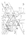
- FIG. 3 is a perspective view of a section of a facade structure according to the invention shown.
- the articulated fixing of the holding elements 10a on the primary building construction increases the freedom of movement of the Facade construction 1, but still allows the removal on the Facade construction 1 loads on the primary building construction.
- the facade structure 1 does not have to apply any prestressing forces to the facade elements 20 in the holding elements 10a, 10b set. Instead, there are slight differences in distance, such as those found in Within the usual tolerances result in one in the support structure Moving the support elements 11 relative to the holding elements 10a, 10b and thus to compensate.
- FIG. 4 is an exploded view for a fixation on the primary facade 2 equipped holding element 10a shown.
- Holding element 10a made of a basic element with two spherical bearing sections 102 and a web 107 connecting them. Slots 106 are in the web 107 shaped, which serve as holding slots for attaching the facade elements 20.
- On the web 107 are screwed to the side parts 108 by means of bolts 109.
- a fastening cover 110 is attached to the web 107 by means of bolts 111 put on and protrudes beyond the side parts 108. With the joint bearing sections 102 Support elements 11 are shown connected.
- the holding element 10a instructs one of the spherical bearing sections 102 on an extension 112, in which one Bearing opening 113 is introduced in the form of an elongated hole.
- the holding element 10a With this extension 112 and the bearing opening 113 arranged thereon, the holding element 10a a bearing connection L, which is rigid with the primary building construction is connected to be fastened with a bearing pin 118.
- a bearing sleeve 119 is placed on it.
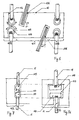
- FIG. 5 is a schematic perspective view of a holding element 10, which either as a holding element 10a with extension or as a holding element 10b can be formed without an extension.
- a holding element 10a with extension or as a holding element 10b can be formed without an extension.
- the bearing section 102 In the bearing section 102 are two opposite bearing blocks 103 by means of a bearing pin 104 articulated. 5a, this is again taken in a sectional view shown along the section line A-A in Fig. 5.
- the bearing blocks 103 are Internal screw thread 105 attached, into the free ends of support elements 11 can be screwed.
- Bearing blocks 103 about 2 ° to about 10 ° with respect to the holding element 10 can move.
- FIG. 5b An alternative embodiment of a spherical bearing section 102 is shown in FIG. 5b shown.
- a single bearing block 103 in which from above as from below a support member 11 can be screwed, and which by a Bolt 104 is articulated.
- Such a bearing block allows only one restricted relative movement between the support elements 11 and the Holding element 10, since here both support elements 11 with respect to the Holding element 10 are moved equally.
- a facade structure 1 can have different holding elements 10 with either separate bearing blocks 103 in the spherical bearing section 102 or a continuous bearing block 103 be used.
- the holding elements 10b can be one Bearing block 103 according to FIG. 5b, the holding elements 10a two separate bearing blocks 103 according to FIG. 5a.
- FIG. 6 shows an alternative embodiment of the in a schematic view Spherical bearing sections 102 of a holding element 10 are shown. Here are for Fixing the ends of the support elements 11 in bearing openings 114 articulated arranged rotary anchor 115 provided. These can be compared to the body of the holding element 10 by a maximum angle of 2 ° to approximately depending on the application Can be tilted 10 °. 6 are also shown at an angle ⁇ led obliquely into the holding element 10 with respect to the facade level Holding slots 106, each with a holding slot 106 in the figure from above or from is guided at the bottom into the holding element 10 and these holding slots are parallel to each other.
- Figs. 7 and 7a is a variant of the embodiment shown in FIG. 6 of the spherical bearing section 102 shown, in which the rotary anchor 115 is not in two separate storage openings 114, but in a common, as an elongated hole trained bearing opening 117 are arranged.
- the holding elements functionally can be divided into two separate elements, namely a joint element for connecting support elements and a pure one Holding element, which without an articulated connection to the support or Joint elements is arranged and only the holder of the facade elements serves.
Landscapes
- Engineering & Computer Science (AREA)
- Architecture (AREA)
- Civil Engineering (AREA)
- Structural Engineering (AREA)
- Physics & Mathematics (AREA)
- Electromagnetism (AREA)
- Load-Bearing And Curtain Walls (AREA)
Abstract
Description
- Fig. 1
- eine geschnittene Seitenansicht eines erfindungsgemäßen Fassadenaufbaus,
- Fig. 2
- den in Fig. 1 mit II bezeichneten Ausschnitt in vergrößerter Darstellung,
- Fig. 3
- in perspektivischer Ansicht einen Ausschnitt aus einem erfindungsgemäßen Fassadenaufbau,
- Fig. 4
- in Explosionsdarstellung ein Halteelement aus einem erfindungsgemäßen Fassadenaufbau mit daran anschließenden weiteren Elementen,
- Fig. 5
- schematisch und skizzenhaft den Aufbau eines Halteelementes eines Gelenkabschnitts eines Halteelementes,
- Fig. 5a
- in schematischer Darstellung eine Schnittansicht auf einen Schnitt entlang der Linie A-A in Fig. 5,
- Fig. 5b
- in perspektivischer Darstellung skizzenhaft eine alternative Ausgestaltung eines Lagerblocks für einen Gelenklagerabschnitt eines Halteelementes gemäß Fig. 5,
- Fig. 6
- in schematisch geschnittener Seitenansicht ein Halteelement mit alternativ ausgestalteten Gelenklagerabschnitten sowie in dem Halteabschnitt ausgebildeten Halteschlitzen,
- Fig. 7
- eine Variante zu dem Halteabschnitt gemäß Fig. 6 in schematischer Seitenansicht und
- Fig. 7a
- ebenfalls in schematischer Ansicht die in Fig. 7 dargestellte Variante in geschnittener Vorderansicht.
- 1
- Fassadenaufbau
- 2
- Primärfassade
- 10
- Halteelement
- 10a
- Halteelement
- 10b
- Halteelement
- 11
- Tragelement
- 12
- Führungselement
- 20
- Fassadenelement
- 101
- Halteabschnitt
- 102
- Gelenklagerabschnitt
- 103
- Lagerblock
- 104
- Bolzen
- 105
- Gewinde
- 106
- Schlitz
- 107
- Steg
- 108
- Seitenteil
- 109
- Bolzen
- 110
- Befestigungsdeckel
- 111
- Bolzen
- 112
- Fortsatz
- 113
- Lageröffnung
- 114
- Lageröffnung
- 115
- Drehanker
- 116
- elastisches Element
- 117
- Lageröffnung
- 118
- Bolzen
- 119
- Lagerhülse
- α
- Winkel
- S
- Abstand
- L
- Lageranschluß
Claims (17)
- Fassadenaufbau gebildet aus mehreren in einer Tragkonstruktion gehaltenen, im wesentlichen plattenförmigen Fassadenelementen (20), insbesondere Glaselementen, wobei die Tragkonstruktion im wesentlichen vertikal entlang der Fassade verlaufende, lastaufnehmende Tragelemente (11) und mit den Tragelementen (11) verbundene Halteelemente (10, 10a,10b) aufweist, wobei die Fassadenelemente (20) in den Halteelementen (10, 10a, 10b) gelagert und die Halteelemente (10, 10a, 10b) mit den Tragelementen (11) gelenkig verbunden sind.
- Fassadenaufbau nach Anspruch 1, gekennzeichnet durch stab- oder seilförmige Tragelemente (11).
- Fassadenaufbau nach einem der Ansprüche 1 oder 2, dadurch gekennzeichnet, daß die Tragelemente (11) mit den Halteelementen (10, 10a, 10b) derart gelenkig verbunden sind, daß sie relativ zu den Halteelementen (10, 10a, 10b) wenigstens in einer senkrecht zu einer Fassadenebene verlaufenden, im wesentlichen vertikalen Ebene bewegbar sind.
- Fassadenaufbau nach Anspruch 3, dadurch gekennzeichnet, daß die Tragelemente (11) um einen Winkel von zwischen 2° und 10° relativ zu den mit diesen gelenkig verbundenen Halteelementen (10, 10a, 10b) bewegt werden können.
- Fassadenaufbau nach einem der voranstehenden Ansprüche, dadurch gekennzeichnet, daß die Fassadenelemente (20) im Bereich ihrer Oberkante sowie Unterkante in Halteschlitzen (106) der Halteelemente (10, 10a, 10b) gehalten sind.
- Fassadenaufbau nach einem der voranstehenden Ansprüche, dadurch gekennzeichnet, daß die Fassadenelemente (20) unter einem Winkel (α) zu der im wesentlichen vertikal verlaufenden Fassadenebene angeordnet sind und einander so überlappen, daß jeweils eine Oberkante eines unteren Fassadenelementes (20) von der Unterkante eines darüber angeordneten Fassadenelementes (20) überlappt wird.
- Fassadenaufbau nach einem der voranstehenden Ansprüche, dadurch gekennzeichnet, daß dieser eine einer Primärfassade (2) eines Gebäudes vorgesetzte Sekundärfassade ist und daß wenigstens ein Teil der Halteelemente (10a) an der primären Gebäudekonstruktion festgelegt ist.
- Fassadenaufbau nach Anspruch 7, dadurch gekennzeichnet, daß die an der primären Gebäudekonstruktion festgelegten Halteelemente (10a) gelenkig an dieser festgelegt sind und zwar derart, daß die Verbindung eine Bewegung der Halteelemente (10b) relativ zu der primären Gebäudekonstruktion wenigstens in einer auf der Fassadenebene der Sekundärfassade senkrecht stehenden, im wesentlichen vertikal verlaufenden Ebene ermöglicht.
- Fassadenaufbau nach einem der voranstehenden Ansprüche, dadurch gekennzeichnet, daß an einem Halteelement (10, 10a, 10b) jeweils zwei in einer im wesentlichen horizontalen Reihe angeordnete Fassadenelemente (20) vorzugsweise unter Belassung einer Stoßfuge aneinander angrenzen, wobei an zwischen zwei solcher horizontaler Reihen aus Fassadenelementen (20) angeordnete Halteelemente (10, 10a, 10b) zugleich Fassadenelemente (20) aus den beiden übereinanderliegenden Reihen vorzugsweise ebenfalls unter Belassung einer Stoßfuge aneinander angrenzen.
- Halteelement zur Verwendung in einem Fassadenaufbau (1) nach einem der voranstehenden Ansprüche mit einem Gelenklagerabschnitt (102) zum Aufnehmen und gelenkigen Lagern eines freien Endes eines im wesentlichen stab- oder seilförmigen Tragelementes (11) und einem Halteabschnitt (101) zum Aufnehmen eines mit dem Halteelement (10, 10a, 10b) zu haltenden Fassadenelementes (20).
- Halteelement nach Anspruch 10, dadurch gekennzeichnet, daß es zwei einander axial gegenüberliegende Gelenklagerabschnitte (102) und einen zwischen diesen Gelenklagerabschnitten (102) verlaufenden Halteabschnitt (101) mit Halterungen für ein oberes und ein unteres Fassadenelement (20) aufweist.
- Halteelement nach Anspruch 11, dadurch gekennzeichnet, daß die Halterungen als Halteschlitze (106) ausgebildet sind.
- Halteelement nach einem der Ansprüche 11 oder 12, dadurch gekennzeichnet, daß es im wesentlichen quaderförmig geformt ist, wobei im Bereich der Stirnseiten auf jeweils zwei einander gegenüberliegenden Längsflächen Anschlüsse zum Verbinden eines in dem Quader befindlichen Gelenks mit den Tragelementen (11) so angeordnet sind, daß die mit dem Gelenk verbundenen Tragelemente (11) im wesentlichen senkrecht zu den Längsflächen verlaufen, wobei jeweils zwei entlang der Schmalseiten des Quaders einander gegenüberliegende Tragelemente (11) zueinander fluchten.
- Halteelement nach Anspruch 13, dadurch gekennzeichnet, daß im Bereich zwischen den Anschlüssen parallel zu den Schmalkanten des Quaders verlaufende und quer zur Lotrichtung der Längsseite mit den Anschlüssen in den Quader geführte Schlitze (106) als Halterungen für die Fassadenelemente (20) angeordnet sind.
- Halteelement nach Anspruch 14, dadurch gekennzeichnet, daß ein erster Schlitz (106) in eine erste mit einem Anschluß versehene Längsseite des Quaders und parallel zu dem ersten Schlitz (106) ein zweiter Schlitz (106) in die gegenüberliegende Seite geführt ist.
- Halteelement nach einem der Ansprüche 10 bis 15, dadurch gekennzeichnet, daß dieses mehrteilig aufgebaut ist.
- Halteelement nach einem der Ansprüche 10 bis 16, dadurch gekennzeichnet, daß an diesem ein Fortsatz (112) ausgebildet ist, der eine Befestigungsstruktur (113) zum gelenkigen Festlegen des Halteelementes (10a) an einem beispielsweise in der primären Gebäudekonstruktion ausgebildeten Befestigungspunkt (L) aufweist.
Applications Claiming Priority (2)
| Application Number | Priority Date | Filing Date | Title |
|---|---|---|---|
| DE10304833A DE10304833A1 (de) | 2003-02-06 | 2003-02-06 | Fassadenaufbau sowie Halteelement zur Verwendung in einem solchen |
| DE10304833 | 2003-02-06 |
Publications (2)
| Publication Number | Publication Date |
|---|---|
| EP1445390A2 true EP1445390A2 (de) | 2004-08-11 |
| EP1445390A3 EP1445390A3 (de) | 2005-09-28 |
Family
ID=32603179
Family Applications (1)
| Application Number | Title | Priority Date | Filing Date |
|---|---|---|---|
| EP04002275A Withdrawn EP1445390A3 (de) | 2003-02-06 | 2004-02-03 | Fassadenaufbau sowie Halteelement zur Verwendung in einem solchen Fassadenaufbau |
Country Status (2)
| Country | Link |
|---|---|
| EP (1) | EP1445390A3 (de) |
| DE (1) | DE10304833A1 (de) |
Cited By (2)
| Publication number | Priority date | Publication date | Assignee | Title |
|---|---|---|---|---|
| FR3113502A1 (fr) * | 2020-08-20 | 2022-02-25 | André AKERIB | Dispositif de panneau vitré et procédé d'implantation associé |
| EP4539335A1 (de) * | 2023-10-09 | 2025-04-16 | Simone Mela | Gebäudemodul |
Families Citing this family (3)
| Publication number | Priority date | Publication date | Assignee | Title |
|---|---|---|---|---|
| DE202008012164U1 (de) * | 2008-09-13 | 2010-02-11 | Längle Glas GmbH | Glasfassade |
| CN102051932B (zh) * | 2009-12-29 | 2012-01-25 | 北京江河幕墙股份有限公司 | 双自由度调节拉索幕墙 |
| CN104018585A (zh) * | 2014-04-15 | 2014-09-03 | 苏州金螳螂建筑装饰股份有限公司 | 玻璃幕墙横梁与立柱新型连接结构 |
Family Cites Families (4)
| Publication number | Priority date | Publication date | Assignee | Title |
|---|---|---|---|---|
| DE4005676A1 (de) * | 1990-02-22 | 1991-08-29 | Buchtal Gmbh | Absorber fuer elektromagnetische wellen |
| AT1255U1 (de) * | 1995-09-11 | 1997-01-27 | Feigl Bernhard | Fassade |
| DE19901757A1 (de) * | 1999-01-18 | 2000-07-20 | Schueco Int Kg | Fassade oder Lichtdach mit Scheiben oder Füllungsplatten versetzt zum Scheiben- oder Plattenrand halternden Beschlägen |
| DE19911490A1 (de) * | 1999-01-29 | 2000-08-03 | Paul Schlosbauer | Verstellbare Fassadenschale mit einem Tragrahmen für ein Gebäude |
-
2003
- 2003-02-06 DE DE10304833A patent/DE10304833A1/de not_active Withdrawn
-
2004
- 2004-02-03 EP EP04002275A patent/EP1445390A3/de not_active Withdrawn
Cited By (2)
| Publication number | Priority date | Publication date | Assignee | Title |
|---|---|---|---|---|
| FR3113502A1 (fr) * | 2020-08-20 | 2022-02-25 | André AKERIB | Dispositif de panneau vitré et procédé d'implantation associé |
| EP4539335A1 (de) * | 2023-10-09 | 2025-04-16 | Simone Mela | Gebäudemodul |
Also Published As
| Publication number | Publication date |
|---|---|
| EP1445390A3 (de) | 2005-09-28 |
| DE10304833A1 (de) | 2004-08-19 |
Similar Documents
| Publication | Publication Date | Title |
|---|---|---|
| EP0784126B1 (de) | Gebäudeskelett aus Profilstäben | |
| DE3736553A1 (de) | Wandverbindungsteil | |
| DE3177307T2 (de) | Rahmen zur Einfassung eines Teiles einer Wand. | |
| EP1832690A2 (de) | Bauelement zur Wärmedämmung | |
| DE202017105133U1 (de) | Schwenkbare Halte-, Stütz- und/oder Verstelleinrichtung für Solarmodule | |
| DE2134167B2 (de) | Großflächige Gebäudewand | |
| EP1445390A2 (de) | Fassadenaufbau sowie Halteelement zur Verwendung in einem solchen Fassadenaufbau | |
| EP1954897B1 (de) | Verbindungsknoten für ein Raumtragwerk, insbesondere für eine geodätische Struktur | |
| DE2206973A1 (de) | Raeumliches bauelement zur bildung von trag- und stuetzwerken aller art | |
| DE102017104344B3 (de) | Begrenzung für ein Hochbeet | |
| EP1134328A2 (de) | Profilverbinder für Brandschutzkonstruktionen | |
| EP0086751B1 (de) | Auf Zug beanspruchbarer Anker | |
| EP0596207A1 (de) | Blechprofil, vorzugsweise in kaltgewalzter Ausführung, zum erstellen von Traggerüsten, Bühnen und dgl. | |
| EP2574702B1 (de) | Dach- oder Wandkonstruktion | |
| EP0971084B1 (de) | Schalungsanschlag | |
| DE20301849U1 (de) | Fassadenaufbau sowie Halteelement zur Verwendung in einem solchen | |
| DE3128505C2 (de) | Vorrichtung zur Verbindung einer hölzernen Fachwerksäule mit hölzernen Fachwerkträgern | |
| DE202008017065U1 (de) | Verbindungsvorrichtung | |
| DE10253500A1 (de) | Keramikbauelement zur Anordnung in einem Bauwerk | |
| DE102010027368B4 (de) | Vorrichtung zur Eckbefestigung einer Leibungsplatte | |
| DE202017101192U1 (de) | Begrenzung für ein Hochbeet | |
| DE202020102155U1 (de) | Modular aufbaubares Gebäudeträgergerüst | |
| EP4050170B1 (de) | Bauwerk mit thermisch isolierendem bauelement | |
| DE2820920A1 (de) | Isolierbauplatte fuer wandkonstruktionen | |
| CH681314A5 (de) |
Legal Events
| Date | Code | Title | Description |
|---|---|---|---|
| PUAI | Public reference made under article 153(3) epc to a published international application that has entered the european phase |
Free format text: ORIGINAL CODE: 0009012 |
|
| AK | Designated contracting states |
Kind code of ref document: A2 Designated state(s): AT BE BG CH CY CZ DE DK EE ES FI FR GB GR HU IE IT LI LU MC NL PT RO SE SI SK TR |
|
| AX | Request for extension of the european patent |
Extension state: AL LT LV MK |
|
| PUAL | Search report despatched |
Free format text: ORIGINAL CODE: 0009013 |
|
| AK | Designated contracting states |
Kind code of ref document: A3 Designated state(s): AT BE BG CH CY CZ DE DK EE ES FI FR GB GR HU IE IT LI LU MC NL PT RO SE SI SK TR |
|
| AX | Request for extension of the european patent |
Extension state: AL LT LV MK |
|
| AKX | Designation fees paid |
Designated state(s): AT BE BG CH CY CZ DE DK EE ES FI FR GB GR HU IE IT LI LU MC NL PT RO SE SI SK TR |
|
| STAA | Information on the status of an ep patent application or granted ep patent |
Free format text: STATUS: THE APPLICATION IS DEEMED TO BE WITHDRAWN |
|
| 18D | Application deemed to be withdrawn |
Effective date: 20060329 |