EP1445516B1 - Boîte de vitesses automatique à rapports multiples - Google Patents
Boîte de vitesses automatique à rapports multiples Download PDFInfo
- Publication number
- EP1445516B1 EP1445516B1 EP04001622A EP04001622A EP1445516B1 EP 1445516 B1 EP1445516 B1 EP 1445516B1 EP 04001622 A EP04001622 A EP 04001622A EP 04001622 A EP04001622 A EP 04001622A EP 1445516 B1 EP1445516 B1 EP 1445516B1
- Authority
- EP
- European Patent Office
- Prior art keywords
- speed
- clutch
- vehicle speed
- input shaft
- shift
- Prior art date
- Legal status (The legal status is an assumption and is not a legal conclusion. Google has not performed a legal analysis and makes no representation as to the accuracy of the status listed.)
- Expired - Lifetime
Links
Images

Classifications
-
- F—MECHANICAL ENGINEERING; LIGHTING; HEATING; WEAPONS; BLASTING
- F16—ENGINEERING ELEMENTS AND UNITS; GENERAL MEASURES FOR PRODUCING AND MAINTAINING EFFECTIVE FUNCTIONING OF MACHINES OR INSTALLATIONS; THERMAL INSULATION IN GENERAL
- F16H—GEARING
- F16H61/00—Control functions within control units of change-speed- or reversing-gearings for conveying rotary motion ; Control of exclusively fluid gearing, friction gearing, gearings with endless flexible members or other particular types of gearing
- F16H61/04—Smoothing ratio shift
- F16H61/0437—Smoothing ratio shift by using electrical signals
-
- F—MECHANICAL ENGINEERING; LIGHTING; HEATING; WEAPONS; BLASTING
- F16—ENGINEERING ELEMENTS AND UNITS; GENERAL MEASURES FOR PRODUCING AND MAINTAINING EFFECTIVE FUNCTIONING OF MACHINES OR INSTALLATIONS; THERMAL INSULATION IN GENERAL
- F16H—GEARING
- F16H2200/00—Transmissions for multiple ratios
- F16H2200/003—Transmissions for multiple ratios characterised by the number of forward speeds
- F16H2200/0052—Transmissions for multiple ratios characterised by the number of forward speeds the gear ratios comprising six forward speeds
-
- F—MECHANICAL ENGINEERING; LIGHTING; HEATING; WEAPONS; BLASTING
- F16—ENGINEERING ELEMENTS AND UNITS; GENERAL MEASURES FOR PRODUCING AND MAINTAINING EFFECTIVE FUNCTIONING OF MACHINES OR INSTALLATIONS; THERMAL INSULATION IN GENERAL
- F16H—GEARING
- F16H2306/00—Shifting
- F16H2306/40—Shifting activities
- F16H2306/44—Removing torque from current gears
-
- F—MECHANICAL ENGINEERING; LIGHTING; HEATING; WEAPONS; BLASTING
- F16—ENGINEERING ELEMENTS AND UNITS; GENERAL MEASURES FOR PRODUCING AND MAINTAINING EFFECTIVE FUNCTIONING OF MACHINES OR INSTALLATIONS; THERMAL INSULATION IN GENERAL
- F16H—GEARING
- F16H2306/00—Shifting
- F16H2306/40—Shifting activities
- F16H2306/50—Coupling of new gear
-
- F—MECHANICAL ENGINEERING; LIGHTING; HEATING; WEAPONS; BLASTING
- F16—ENGINEERING ELEMENTS AND UNITS; GENERAL MEASURES FOR PRODUCING AND MAINTAINING EFFECTIVE FUNCTIONING OF MACHINES OR INSTALLATIONS; THERMAL INSULATION IN GENERAL
- F16H—GEARING
- F16H2306/00—Shifting
- F16H2306/40—Shifting activities
- F16H2306/52—Applying torque to new gears
-
- F—MECHANICAL ENGINEERING; LIGHTING; HEATING; WEAPONS; BLASTING
- F16—ENGINEERING ELEMENTS AND UNITS; GENERAL MEASURES FOR PRODUCING AND MAINTAINING EFFECTIVE FUNCTIONING OF MACHINES OR INSTALLATIONS; THERMAL INSULATION IN GENERAL
- F16H—GEARING
- F16H2312/00—Driving activities
- F16H2312/16—Coming to a halt
-
- F—MECHANICAL ENGINEERING; LIGHTING; HEATING; WEAPONS; BLASTING
- F16—ENGINEERING ELEMENTS AND UNITS; GENERAL MEASURES FOR PRODUCING AND MAINTAINING EFFECTIVE FUNCTIONING OF MACHINES OR INSTALLATIONS; THERMAL INSULATION IN GENERAL
- F16H—GEARING
- F16H3/00—Toothed gearings for conveying rotary motion with variable gear ratio or for reversing rotary motion
- F16H3/006—Toothed gearings for conveying rotary motion with variable gear ratio or for reversing rotary motion power being selectively transmitted by parallel flow paths, e.g. dual clutch transmissions
-
- F—MECHANICAL ENGINEERING; LIGHTING; HEATING; WEAPONS; BLASTING
- F16—ENGINEERING ELEMENTS AND UNITS; GENERAL MEASURES FOR PRODUCING AND MAINTAINING EFFECTIVE FUNCTIONING OF MACHINES OR INSTALLATIONS; THERMAL INSULATION IN GENERAL
- F16H—GEARING
- F16H61/00—Control functions within control units of change-speed- or reversing-gearings for conveying rotary motion ; Control of exclusively fluid gearing, friction gearing, gearings with endless flexible members or other particular types of gearing
- F16H61/68—Control functions within control units of change-speed- or reversing-gearings for conveying rotary motion ; Control of exclusively fluid gearing, friction gearing, gearings with endless flexible members or other particular types of gearing specially adapted for stepped gearings
- F16H61/684—Control functions within control units of change-speed- or reversing-gearings for conveying rotary motion ; Control of exclusively fluid gearing, friction gearing, gearings with endless flexible members or other particular types of gearing specially adapted for stepped gearings without interruption of drive
- F16H61/688—Control functions within control units of change-speed- or reversing-gearings for conveying rotary motion ; Control of exclusively fluid gearing, friction gearing, gearings with endless flexible members or other particular types of gearing specially adapted for stepped gearings without interruption of drive with two inputs, e.g. selection of one of two torque-flow paths by clutches
-
- Y—GENERAL TAGGING OF NEW TECHNOLOGICAL DEVELOPMENTS; GENERAL TAGGING OF CROSS-SECTIONAL TECHNOLOGIES SPANNING OVER SEVERAL SECTIONS OF THE IPC; TECHNICAL SUBJECTS COVERED BY FORMER USPC CROSS-REFERENCE ART COLLECTIONS [XRACs] AND DIGESTS
- Y10—TECHNICAL SUBJECTS COVERED BY FORMER USPC
- Y10T—TECHNICAL SUBJECTS COVERED BY FORMER US CLASSIFICATION
- Y10T74/00—Machine element or mechanism
- Y10T74/19—Gearing
- Y10T74/19219—Interchangeably locked
- Y10T74/19251—Control mechanism
- Y10T74/19256—Automatic
- Y10T74/1926—Speed responsive
Definitions
- the present invention relates in general to multistage automatic transmissions for wheeled motor vehicles as for example known from EP 1 122 116 A2 , and more particularly to the multistage automatic transmissions of a constant-mesh type. More specifically, the present invention is concerned with the multistage automatic transmission having a speed change control system incorporated therewith.
- first and second concentric input shafts there are arranged first and second concentric input shafts, synchromesh gear pairs, a first clutch for establishing connection/disconnection between an associated engine and the first input shaft, and a second clutch for establishing connection/disconnection between the engine and the second input shaft.
- the gear change is carried out by suitably switching ON/OFF operation of the first and second clutches.
- a gear-to-gear ratio between the first and second speeds is set larger than that between other speeds in view of expected power and fuel consumption performances.
- the deceleration shock felt by passengers is higher than that in other downshift operations. This is because the rotation speed gap of the input shaft or shafts and an inertia force of the engine show marked values at such downshift operation.
- a multistage automatic transmission which, upon downshift operation from the second speed to the first speed by the driver, carries out a smoothed downshifting of the transmission without deteriorating the running performance of the associated motor vehicle.
- a multistage automatic transmission for use in a motor vehicle, which comprises first and second clutches each selectively establishing and disestablishing a torque transmission path from an engine; a first input shaft connected to the first clutch and having a first speed drive gear tightly mounted thereon; a second input shaft coaxially arranged with the first input shaft and connected to the second clutch, the second input shaft having a second speed drive gear rotatably mounted thereon; an output shaft extending in parallel with the first and second input shafts, the output shaft having a first speed driven gear rotatably mounted thereon and a second speed driven gear tightly mounted thereon, the first and second speed driven gears being meshed with the first and second speed drive gears respectively; a first shift clutch for uniting the first speed driven gear with the output shaft when actuated; a second shift clutch for uniting the second speed drive gear with the second input shaft when actuated; and a control system for controlling the first and second clutches and the first and second shift clutches to provide the
- a multistage automatic transmission for use in a motor vehicle, which comprises first and second clutches each selectively establishing and disestablishing a torque transmission path from an engine; a first input shaft connected to the first clutch and having a first speed drive gear tightly mounted thereon; a second input shaft coaxially arranged with the first input shaft and connected to the second clutch, the second input shaft having a second speed drive gear rotatably mounted thereon; an output shaft extending in parallel with the first and second input shafts, the output shaft having a first speed driven gear rotatably mounted thereon and a second speed driven gear tightly mounted thereon, the first and second speed driven gears being meshed with the first and second speed drive gears respectively; a first shift clutch for uniting the first speed driven gear with the output shaft when actuated; a second shift clutch for uniting the second speed drive gear with the second input shaft when actuated; and a control system for controlling the first and second clutches and the first and second shift clutches to provide the
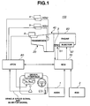
- a speed change control system 100 that is operatively applied to a multistage automatic transmission, which is an embodiment of the present invention.
- Engine 60 is an engine, such as an internal combustion engine.
- Engine 60 has at its intake section an electronically controlled throttle 61 that electronically controls a throttle opening of an air intake passage.
- Engine 60 has also fuel injectors 62 each being exposed to a cylinder of engine 60 for injecting fuel thereinto.
- a multistage automatic transmission 20 is connected to an output shaft of engine 60 through an electromagnetic clutch 40.
- Engine 60 is controlled by an engine control unit (ECU) 70, and transmission 20 is controlled by a transmission control unit (ATCU) 80.
- Each of the control units 70 and 80 has a micro-computer that includes CPU (central processing unit), RAM (random access memory), ROM (read only memory, and input and output interfaces.
- an accelerator open degree sensor (AODS) 1, an engine speed sensor (ESS) 2 and a throttle open degree sensor 3 feed engine control unit 70 with corresponding information signals.
- Transmission control unit 80 is fed with a vehicle speed signal and a range signal (inhibitor signal).
- the range signal is a signal that represents the range that has been just selected by the driver.
- Engine control unit 70 and transmission control unit 80 are electrically connected to exchange information signals.
- engine control unit 70 Upon processing the information signals fed thereto, engine control unit 70 issues control signals for controlling the throttle opening and the amount of fuel injected to each cylinder. Like this, upon processing the information signals fed thereto, transmission control unit 80 issues control signals for controlling a speed change actuator "A” and two clutch actuators "a” and “b” of electromagnetic clutch 40.
- Transmission 20 has electromagnetic clutch 40 operatively connected thereto.
- Electromagnetic clutch 40 is of a twin type comprising a first clutch 40a which carries out engagement/disengagement between a first input shaft 21 and an engine output shaft 6 with the aid of clutch actuator "a” (see Fig. 1 ), and a second clutch 40b which carries out engagement/disengagement between a second input shaft 22 and engine output shaft 6 with the aid of the other clutch actuator "b" (see Fig. 1 ).
- first, third and fifth speed drive gears 31, 33 and 35 Disposed about first input shaft 21 are first, third and fifth speed drive gears 31, 33 and 35 and a first reverse gear R1.
- First speed drive gear 31 and first reverse gear R1 are integral with first input shaft 21, while third and fifth speed drive gears 33 and 35 are rotatably disposed on first input shaft 21.
- Rotatably disposed about first input shaft 21 is a second input shaft 22.
- second, fourth and sixth speed drive gears 32, 34 and 36 Disposed about second input shaft 22 are second, fourth and sixth speed drive gears 32, 34 and 36.
- Sixth speed drive gear 36 is integral with second input shaft 22 to rotate therewith, while second and fourth speed drive gears 32 and 34 are rotatably disposed about second input shaft 22.
- An output shaft 23 and an auxiliary shaft 24 extend beside and in parallel with first and second input shafts 21 and 22. Disposed about output shaft 23 are first, second, third, fourth, fifth and sixth speed driven gears 41, 42, 43, 44, 45 and 46 and a third reverse gear R3. Second, third, fourth and fifth speed driven gears 42, 43, 44 and 45 and third reverse gear R3 are integral with output shaft 23 to rotate therewith, while, first and sixth speed driven gear 41 and 46 are rotatably disposed about output shaft 23.
- auxiliary shaft 24 Rotatably disposed about auxiliary shaft 24 is a second reverse gear R2.
- first input shaft 21 Disposed on first input shaft 21 is a 3-5 shift clutch 210 that carries out engagement/disengagement between third speed drive gear 33 and first input shaft 21 and/or that between fifth speed drive gear 35 and first input shaft 21.
- a 2-4 shift clutch 220 Disposed on second input shaft 22 is a 2-4 shift clutch 220 that carries out engagement/disengagement between second speed drive gear 32 and second input shaft 22 and/or that between fourth speed drive gear 34 and second input shaft 22.
- a 1-6 shift clutch 230 Disposed on output shaft 23 is a 1-6 shift clutch 230 that carries out engagement/disengagement between first speed driven gear 41 and output shaft 23 and/or that between sixth speed driven gear 46 and output shaft 23.
- auxiliary shaft 24 Disposed on auxiliary shaft 24 is a reverse clutch 240 that takes both an engaged condition wherein second reverse gear R2 is meshed with both first and third reverse gears R1 and R3 and a disengaged condition wherein second reverse gear R2 is released from both first and third reverse gears R1 and R3.
- shift clutch 210, 2-4 shift clutch 220, 1-6 shift clutch 230 and reverse shift clutch 240 are actuated by speed change actuator "A" (see Fig. 1 ). That is, upon receiving a speed change instruction, each shift clutch 210, 220, 230 or 240 effects the engagement or disengagement for providing a torque transmission path that is needed.
- first and second clutches 40a and 40b Under cruising, that is, when the associated motor vehicle is moving without carrying out the speed change, both first and second clutches 40a and 40b assume the engaged condition and a torque transmission is effected through either one of the first and second clutches 40a and 40b.
- both first and second clutches 40a and 40b are in their disengaged condition. It is to be noted that the neutral condition is also achieved even when first and second clutches 40a and 40b assume their engaged condition so long as the shift clutches 210, 220, 230 and 240 are in their neutral positions.
- First clutch 40a is operatively engaged, and by 1-6 shift clutch 230, first speed driven gear 41 is united with output shaft 23. Under this condition, the engine torque from the engine is transmitted to first clutch 40a, first input shaft 21, first speed drive gear 31, first speed driven gear 41 and output shaft 23 and then to a final reduction gear (not shown).
- Second clutch 40b is operatively engaged, and by 2-4 shift clutch 220, second speed drive gear 32 is united with second input shaft 22. Under this condition, the engine torque from the engine is transmitted to second clutch 40b, second input shaft 22, second speed drive gear 32, second speed driven gear 42 and output shaft 23 and then to the final reduction gear (not shown).
- First clutch 40a is operatively engaged, and by 3-5 shift clutch 210, third speed drive gear 33 is united with first input shaft 21. Under this condition, the engine torque from the engine is transmitted to first clutch 40a, first input shaft 21, third speed drive gear 33, third speed driven gear 43 and output shaft 23 and then to the final reduction gear (not shown).
- Second clutch 40b is operatively engaged, and by 2-4 shift clutch 220, fourth speed drive gear 34 is united with second input shaft 22. Under this condition, the engine torque from the engine is transmitted to second clutch 40b, second input shaft 22, fourth speed drive gear 34, fourth speed driven gear 44 and output shaft 23 and then to the final reduction gear (not shown).
- First clutch 40a is operatively engaged, and by 3-5 shift clutch 210, fifth speed drive gear 35 is united with first input shaft 21. Under this condition, the engine torque from the engine is transmitted to first clutch 40a, first input shaft 21, fifth speed drive gear 35, fifth speed driven gear 45 and output shaft 23 and then to the final reduction gear (not shown).
- Second clutch 40b is operatively engaged, and by 1-6 shift clutch 230, sixth speed driven gear 46 is united with output shaft 23. Under this condition, the engine torque from the engine is transmitted to second clutch 40b, second input shaft 22, sixth speed drive gear 36, sixth speed driven gear 46 and output shaft 23 and then to the final reduction gear (not shown).
- First clutch 40a is operatively engage, and by reverse clutch 240, second reverse gear R2 is meshed with both first and third reverse gears R1 and R3. Under this condition, the engine torque from the engine is transmitted to first clutch 40a, first input shaft 21, first reverse gear R1, second reverse gear R2, third reverse gear R3 and output shaft 23 and to the final reduction gear (not shown).
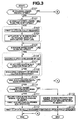
- FIG. 3 and 4 there are shown flowcharts showing programmed operation steps that are executed by transmission control unit (ATCU) 80 when a downshift from the second speed to the first speed is carried out.
- ATCU transmission control unit
- second clutch 40b is operatively engaged, and by 2-4 shift clutch 220 (that is, by moving this ciutch 220 rightward in Fig. 2 ), second speed drive gear 32 is united with second input shaft 22.
- shift clutches 210, 230 and 240 are in their neutral conditions.
- first clutch 40a is operatively engaged, and by 1-6 shift clutch 230 (that is, by moving this clutch 230 leftward in Fig. 2 ), first speed driven gear 41 is united with output shaft 23.
- step S101 judgment is carried out as to whether the current cruising of the vehicle is under the second speed or not. If NO, that is, when the current cruising is not under the second speed, the operation flow goes to END to stop the control. While, if YES, that is, when the current cruising is under the second speed, the operation flow goes to step S102.
- step S102 judgment is carried out as to whether the current vehicle speed is equal to or lower than a pre-shift vehicle speed "V1" for 2 -> 1 speed change or not.
- the pre-shift vehicle speed "V1" for 2 -> 1 speed change is a speed that is basically needed for the 2 -> 1 speed change. If NO, that is, when the current vehicle speed is higher than the pre-shift vehicle speed "V1”, the operation flow returns back to an input part of this step S102. If YES, that is, when the current vehicle speed is lower than the pre-shift vehicle speed "V1", the operation flow goes to step S103.
- step S103 first clutch 40a (see Fig. 2 ) is fully disengaged or released.
- step S104 speed change actuator "A” is energized to move 1-6 shift clutch 230 leftward in Fig. 2 to engage first speed driven gear 41 with output shaft 23.
- speed change actuator "A” is energized to move 1-6 shift clutch 230 leftward in Fig. 2 to engage first speed driven gear 41 with output shaft 23.
- first clutch 40a because of the disengaged condition of first clutch 40a, the engagement of first speed driven gear 41 with output shaft 23 does not induce the torque transmission from the engine to output shaft 23.
- step S105 judgment is carried out as to whether the current engine speed is generally the same as an idling speed of the engine or not. If NO, that is, when the current engine speed is not the same as the idling speed, the operation flow returns back to an input part of this step S105. While, if YES, that is, when the current engine speed is generally the same as the idling speed, the operation flow goes to step S106.
- step S106 second clutch 40b is released by a degree of " ⁇ X”. Then, operation flow goes to step S107.
- step S107 judgment is carried out as to whether a slip degree of second clutch 40b is equal to or greater than a predetermined degree " ⁇ T1" or not. If NO, that is, when the slip degree of second clutch 40b is smaller than the predetermined degree " ⁇ T1", the operation flow returns back to step S106. If YES, that is, when the slip degree is equal to or greater than the predetermined degree " ⁇ T1", the operation flow goes to step S108.
- step S108 an engaging capacity of second clutch 40b is maintained. Then, the operation flow goes to step S109.
- step S109 judgment is carried out as to whether an accelerator pedal has been depressed or not. If NO, that is, when the accelerator pedal has not been depressed, the operation flow goes to step S201 of the auxiliary part of the flowchart of Fig. 4 , which will be described in detail hereinafter. If YES, that is, when the accelerator pedal has been depressed, the operation flow goes to step S110.
- step S110 judgment is carried out as to whether a condition suitable for 2 -> 1 speed change (or 2 -> 1 downshift speed change) has been established or not. If NO, that is, when such condition has not been established, the operation flow goes to S113 which will be described in detail hereinafter. While, if YES, that is, when such condition has been already established, the operation flow goes to step S111.
- transmission control unit (ATCU) 80 issues to engine control unit (ECU) 70 an instruction signal representative of an engine torque needed at the speed change, and an engaging capacity of first clutch 40a is gradually increased and at the same time, the engaging capacity of second clutch 40b is gradually decreased. Then, the operation flow goes to step S112.
- step S112 first clutch 40a is fully engaged.
- step S110 that is, when the condition suitable for the 2 -> 1 speed change has not been established, the operation flow goes to step S113.
- transmission control unit (ATCU) 80 issues to engine control unit (ECU) 70 an instruction signal representative of an engine torque provided when second clutch 40b is fully engaged. That is, under such condition, the 2 -> 1 speed change is not actually carried out. Then, the operation flow goes to step S114.
- step S114 second clutch 40b is fully engaged.
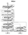
- step S109 that is, when the accelerator pedal has not been depressed, the operation flow goes to step S201 of the flowchart of Fig. 4 .
- step S201 judgment is carried out as to whether the current vehicle speed is equal to or lower than a clutch engagement vehicle speed "V3" for the 2 -> 1 speed change or not. If NO, that is, when the current vehicle speed is higher than the clutch engagement vehicle speed "V3" for the 2 -> 1 speed change, the operation flow returned back to an input part of step S201. While, if YES, that is, when the current vehicle speed is equal to or lower than the clutch engagement vehicle speed "V3" for the 2 -> 1 speed change, the operation flow goes to step S202.
- step S202 second clutch 40b is fully released or disengaged. Then, operation flow goes to step S203.
- step S203 first clutch 40a is engaged by a degree of " ⁇ X”. Then, operation flow goes to step S204.
- step S204 judgment is carried out as to whether a slip degree of first clutch 40a is equal to or smaller than a predetermined degree " ⁇ T2" or not. If NO, that is, when the slip degree of first clutch 40a is larger than the predetermined degree " ⁇ T2”, the operation flow returns to step S203. While, if YES, that is, when the slip degree is equal to or smaller than the predetermined degree " ⁇ T2", the operation flow goes to step S205.
- step S205 the engaging capacity of first clutch 40a is maintained. Then, the operation flow goes to step S206.
- step S206 judgment is carried out as to whether the accelerator pedal has been depressed or not. If NO, that is, when the accelerator pedal has not been depressed, the operation flow goes to step S209 which will be described hereinafter. While, if TES, that is, when the accelerator pedal has been depressed, the operation flow goes to step S207.
- transmission control unit (ATCU) 80 issues to engine control unit (ECU) 70 an instruction signal representative of an engine torque provided when first clutch 40a is fully engaged. Then, the operation flow goes to step S208.
- step S208 first clutch 40a is fully engaged.
- step S206 that is, when the accelerator pedal has not been depressed, the operation flow goes to step S209.
- step S209 judgment is carried out as to whether or not the current vehicle speed has come to a very low speed or zero. If NO, that is, when the current vehicle speed has not come to such very low speed, the operation flow returns to step S206. While, if YES, that is, when the current vehicle speed has come to such very low speed or zero, the operation flow goes to step S210.
- both first and second clutches 40a and 40b are fully released or disengaged.
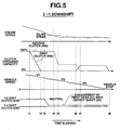
- FIG. 5 there is shown a flowchart that pictorially shows the control of the 2 -> 1 speed downshift in a case wherein depression of the accelerator pedal does not take place and finally the associated motor vehicle stops. More specifically, the control shown by the flowchart of Fig. 5 appears when the operation steps flow through steps S101, S102, S103, S104, S105, S106, S107, S108, S109, S201, S202, S203, S204, S205, S206, S209 and S210 of the flowcharts of Figs. 3 and 4 .
- second clutch 40b Under cruising of the vehicle at the second speed of the transmission, second clutch 40b is operatively engaged and 2-4 shift clutch 220 establishes the engagement between second speed drive gear 32 with second input shaft 22.
- the clutch-half-engaged vehicle speed "V2" is lower than the pre-shift vehicle speed “V1” but higher than the clutch engagement vehicle speed "V3".
- first speed is fully established in the transmission because first clutch 40 takes the engaged condition. It is to be noted that due to the released condition of second clutch 40b, the torque transmission at the second speed is not established.
- second clutch 40b starts its engaging operation. Due to this starting of engaging operation of second clutch 40b, undesired engine stall can be avoided even when a rapid engine braking takes place. Furthermore, when the downshift from the second speed to the first speed is under operation, the actual speed change takes place at the time when the vehicle speed lowers to such a level as not to induce an engine howling. Thus, engine noise that would occur at the downshift operation is suppressed or at least minimized and thus conformable downshift operation from the second speed to the first speed is achieved. As is known, once the transmission has taken the first speed, depression of the accelerator pedal provides the vehicle with a rapid acceleration.
- first clutch 40a As is seen from the time chart of Fig. 5 , once the automatic transmission 20 assumes the first speed from the second speed, the engaging capacity of first clutch 40a is held at a relatively low level. Accordingly, even when, due to reduction in vehicle speed, an engine load is applied to the transmission 20 upon engine braking, undesired engine stall can be avoided. That is, upon such engine braking, a suitable slippage takes place in first clutch 40a to dampen a torque transmission shock.
- the pre-shift vehicle speed "V1" is provided for 2 -> 1 speed change. That is, when the current vehicle speed lowers to the pre-shift vehicle speed "V1”, releasing movement of first clutch 40a that has kept its engaged condition starts, and then, that is, after first clutch 40a is fully released, speed change actuator "A" is energized to operate 1-6 shift clutch 230 to engaged first speed driven gear 41 with output shaft 23. Upon this, the torque transmission path for the first speed is incompletely provided in the transmission 20. Then, when the vehicle speed lowers to the clutch engagement vehicle speed "V3", first clutch 40a becomes engaged with a small engaging capacity. With this, assured and smoothed 2-1 downshift is carried out.
Landscapes
- Engineering & Computer Science (AREA)
- General Engineering & Computer Science (AREA)
- Mechanical Engineering (AREA)
- Control Of Transmission Device (AREA)
Claims (6)
- Transmission automatique à plusieurs étages destinée à être utilisée dans un véhicule à moteur, comprenant :des premier et deuxième embrayages (40a, 40b) établissant et séparant chacun sélectivement une trajectoire de transmission de couple d'un moteur ;un premier arbre d'entrée (21) raccordé au premier embrayage (40a) et ayant un premier engrenage d'entraînement de vitesse (31) monté de manière serrée sur ce dernier ;un deuxième arbre d'entrée (22) agencé de manière coaxiale avec le premier arbre d'entrée (21) et raccordé au deuxième embrayage (40b), le deuxième arbre d'entrée (22) ayant un deuxième engrenage d'entraînement de vitesse (32) monté de manière rotative sur ce dernier ;un arbre de sortie (23) s'étendant parallèlement aux premier et deuxième arbres d'entrée (21, 22), l'arbre de sortie (23) ayant un premier engrenage entraîné de vitesse (41) monté de manière rotative sur ce dernier et un deuxième engrenage entraîné de vitesse (42) monté de manière serrée sur ce dernier, les premier et deuxième engrenages entraînés de vitesse (41, 42) étant engrenés avec les premier et deuxième engrenages d'entraînement de vitesse (31, 32), respectivement ;un premier embrayage de changement de vitesse (230) pour réunir le premier engrenage entraîné de vitesse (41) avec l'arbre de sortie (23) lorsqu'il est actionné ;un deuxième embrayage de changement de vitesse (220) pour réunir le deuxième engrenage d'entraînement de vitesse (32) avec le deuxième arbre d'entrée (22) lorsqu'il est actionné ; et caractérisée par :un système de commande (80) pour commander les premier et deuxième embrayages (40a, 40b) et les premier et deuxième embrayages de changement de vitesse (230, 220) pour fournir la transmission avec une vitesse souhaitée, le système de commande (80) dotant la transmission de la première vitesse en mettant en prise le premier embrayage (40a) et en actionnant le premier embrayage de changement de vitesse (230) et de la deuxième vitesse en mettant en prise le deuxième embrayage (40b) et en actionnant le deuxième embrayage de changement de vitesse (220),dans lequel le système de commande (80) comprend :un dispositif qui émet un signal de vitesse de véhicule représentatif d'une vitesse de véhicule ; etune unité de commande qui est configurée pour réaliser les étapes consistant à :lorsque, après que la transmission est à la deuxième vitesse, la vitesse de véhicule représentée par le signal de vitesse de véhicule devient égale ou inférieure à une première vitesse prédéterminée (V1), commencer l'opération consistant à libérer complètement la condition mise en prise du premier embrayage (40a) ;lorsque, après que la vitesse de véhicule est devenue égale ou inférieure à une deuxième vitesse prédéterminée (V2) qui est inférieure à la première vitesse prédéterminée (V1), commencer l'opération consistant à libérer la condition mise en prise du deuxième embrayage (40b) ; etlorsque, après que la vitesse de véhicule est devenue égale ou inférieure à une troisième vitesse prédéterminée (V3) qui est inférieure à la deuxième vitesse prédéterminée (V2), commencer l'opération consistant à libérer complètement la condition mise en prise du deuxième embrayage (40b) et commencer l'opération consistant à mettre en prise le premier embrayage (40a) à partir de la condition complètement libérée de ce dernier.
- Transmission automatique à plusieurs étages selon la revendication 1, l'unité de commande est configurée pour réaliser en outre l'étape consistant à :lorsqu'un temps prédéterminé s'est écoulé à partir du moment où la vitesse de véhicule est devenue égale ou inférieure à la troisième vitesse prédéterminée (V3), maintenir la force de mise en prise du premier embrayage (40a) à un niveau partiel.
- Transmission automatique à plusieurs étages selon la revendication 2, dans laquelle l'unité de commande est configurée pour réaliser en outre l'étape consistant à :maintenir la force de mise en prise du premier embrayage (40a) au niveau partiel jusqu'à ce que la vitesse de véhicule devienne nulle.
- Transmission automatique à plusieurs étages selon la revendication 1, 2 ou 3, dans laquelle l'unité de commande est configurée pour réaliser en outre l'étape consistant à :lorsque la condition mise en prise du premier embrayage (40a) est complètement libérée, actionner le premier embrayage de changement de vitesse (230) pour réunir le premier engrenage entraîné de vitesse (41) avec l'arbre de sortie (23).
- Transmission automatique à plusieurs étages selon la revendication 1, 2, 3 ou 4, dans laquelle l'unité de commande est configurée pour réaliser en outre l'étape consistant à :une fois que la condition mise en prise du premier embrayage (40a) est complètement libérée, maintenir la condition complètement libérée du premier embrayage (40a) jusqu'à ce que la vitesse de véhicule devienne égale ou inférieure à la troisième vitesse prédéterminée (V3).
- Transmission automatique à plusieurs étages selon la revendication 1, 2, 3, 4 ou 5, dans laquelle l'unité de commande est configurée pour réaliser en outre l'étape consistant à :lorsqu'un temps prédéterminé s'est écoulé à partir du moment où l'opération de libération du deuxième embrayage (40b) commence en raison du fait que la vitesse de véhicule devient également inférieure à la deuxième vitesse prédéterminée (V2), maintenir la force de mise en prise du deuxième embrayage (40b) à un niveau partiel jusqu'à ce que la vitesse de véhicule devienne égale ou inférieure à la troisième vitesse prédéterminée (V3).
Applications Claiming Priority (2)
| Application Number | Priority Date | Filing Date | Title |
|---|---|---|---|
| JP2003027728 | 2003-02-05 | ||
| JP2003027728A JP3826888B2 (ja) | 2003-02-05 | 2003-02-05 | 多段式自動変速機の変速制御装置 |
Publications (3)
| Publication Number | Publication Date |
|---|---|
| EP1445516A2 EP1445516A2 (fr) | 2004-08-11 |
| EP1445516A3 EP1445516A3 (fr) | 2010-02-24 |
| EP1445516B1 true EP1445516B1 (fr) | 2011-08-17 |
Family
ID=32652975
Family Applications (1)
| Application Number | Title | Priority Date | Filing Date |
|---|---|---|---|
| EP04001622A Expired - Lifetime EP1445516B1 (fr) | 2003-02-05 | 2004-01-26 | Boîte de vitesses automatique à rapports multiples |
Country Status (4)
| Country | Link |
|---|---|
| US (1) | US6949051B2 (fr) |
| EP (1) | EP1445516B1 (fr) |
| JP (1) | JP3826888B2 (fr) |
| CN (2) | CN101915303A (fr) |
Cited By (1)
| Publication number | Priority date | Publication date | Assignee | Title |
|---|---|---|---|---|
| DE102024132768B3 (de) | 2024-11-11 | 2026-03-05 | Audi Aktiengesellschaft | Fahrzeug mit einem Doppelkupplungsgetriebe |
Families Citing this family (27)
| Publication number | Priority date | Publication date | Assignee | Title |
|---|---|---|---|---|
| DE50302896D1 (de) * | 2003-08-14 | 2006-05-18 | Getrag Ford Transmissions Gmbh | Verfahren zum Schalten von zwei Kupplungen |
| US7060005B2 (en) * | 2004-01-05 | 2006-06-13 | Diamondback Fitness, Inc. | Exercise device |
| JP2006226380A (ja) * | 2005-02-16 | 2006-08-31 | Toyota Motor Corp | ツインクラッチ式変速機の制御装置 |
| DE102005046648A1 (de) * | 2005-09-29 | 2007-04-05 | Dr.Ing.H.C. F. Porsche Ag | Getriebe |
| JP4828929B2 (ja) * | 2005-12-19 | 2011-11-30 | 日立オートモティブシステムズ株式会社 | 自動変速機の制御装置,制御方法及び自動変速装置 |
| DE102006020064A1 (de) * | 2006-04-29 | 2007-10-31 | Dr.Ing.H.C. F. Porsche Ag | Verfahren zum Anfahren bei Brennkraftmaschinen mit Doppelkupplungsgetriebe |
| DE102007010292B4 (de) | 2007-03-02 | 2018-03-01 | Audi Ag | Schaltvorrichtung für ein Getriebe, insbesondere ein Doppelkupplungs-Wechselgetriebe |
| JP5192166B2 (ja) * | 2007-03-28 | 2013-05-08 | 株式会社小松製作所 | 建設車両 |
| JP5181237B2 (ja) * | 2008-03-26 | 2013-04-10 | 本田技研工業株式会社 | 車両の変速制御装置 |
| JP5232565B2 (ja) * | 2008-08-04 | 2013-07-10 | アイシン・エーアイ株式会社 | デュアルクラッチ式変速機 |
| ITBO20090159A1 (it) * | 2009-03-18 | 2010-09-19 | Ferrari Spa | Metodo di controllo per l'esecuzione di un cambio marcia ascendente in una trasmissione manuale automatica provvista di un cambio a doppia frizione |
| US8485056B2 (en) * | 2009-11-10 | 2013-07-16 | GM Global Technology Operations LLC | Dual clutch multi-speed transmission |
| US8328688B2 (en) | 2010-01-25 | 2012-12-11 | Ford Global Technologies, Llc | Ratio shift control system and method for a multiple-ratio automatic transmission |
| US8337361B2 (en) | 2010-01-25 | 2012-12-25 | Ford Global Technologies, Llc | Multiple-ratio automatic transmission control method and system for ratio upshifts |
| US8775044B2 (en) | 2011-06-08 | 2014-07-08 | Ford Global Technologies, Llc | Clutch torque trajectory correction to provide torque hole filling during a ratio upshift |
| JP5902423B2 (ja) * | 2011-09-20 | 2016-04-13 | アイシン・エーアイ株式会社 | 車両の動力伝達制御装置 |
| JP5787703B2 (ja) * | 2011-10-04 | 2015-09-30 | アイシン・エーアイ株式会社 | デュアルクラッチ式自動変速機 |
| JP5847521B2 (ja) * | 2011-10-05 | 2016-01-20 | アイシン・エーアイ株式会社 | デュアルクラッチ式自動変速機 |
| US8636613B2 (en) | 2011-12-19 | 2014-01-28 | Ford Global Technologies, Llc | Clutch torque trajectory correction to provide torque hole filling during a ratio upshift |
| CN104395648B (zh) | 2012-03-23 | 2017-06-30 | 环太平洋工程产品(1987)有限公司 | 具有提供替选传动比的替选扭矩传输路径的双离合器式动力变速器 |
| CN104380050B (zh) | 2012-03-23 | 2018-03-23 | 环太平洋工程产品(1987)有限公司 | 用于变速器的齿轮接合机构以及相关方法 |
| US8808141B2 (en) | 2012-05-07 | 2014-08-19 | Ford Global Technologies, Llc | Torque hole filling in a hybrid vehicle during automatic transmission shifting |
| JP2014163410A (ja) * | 2013-02-21 | 2014-09-08 | Aisin Seiki Co Ltd | 車両用駆動装置 |
| US8938340B2 (en) | 2013-03-13 | 2015-01-20 | Ford Global Technologies, Llc | Automatic transmission shift control based on clutch torque capacity detection using calculated transmission input torque |
| KR101551009B1 (ko) * | 2013-12-18 | 2015-09-07 | 현대자동차주식회사 | Dct 차량의 변속 제어 방법 |
| KR101826557B1 (ko) * | 2016-05-17 | 2018-02-07 | 현대자동차 주식회사 | 차량의 변속 제어 장치 및 방법 |
| US10399557B2 (en) | 2017-11-10 | 2019-09-03 | Ford Global Technologies, Llc | Engine/motor torque control for torque hole filling in a hybrid vehicle during automatic transmission shifting |
Family Cites Families (13)
| Publication number | Priority date | Publication date | Assignee | Title |
|---|---|---|---|---|
| US4790418A (en) * | 1987-04-30 | 1988-12-13 | Ford Motor Company | Transmission clutch loop transfer control |
| JPH1182729A (ja) | 1997-09-03 | 1999-03-26 | Toyota Motor Corp | ツインクラッチ式自動変速機の変速制御装置 |
| JP3570192B2 (ja) | 1998-01-13 | 2004-09-29 | トヨタ自動車株式会社 | 自動変速機の飛び越しダウンシフト制御装置 |
| US6286381B1 (en) * | 1999-12-17 | 2001-09-11 | Daimlerchrysler Corporation | Gear preselect system for an electro-mechanical automatic transmission having dual input shafts |
| DE10004530B4 (de) * | 2000-02-02 | 2012-11-15 | Volkswagen Ag | Verfahren zur Steuerung eines Doppelkupplungsgetriebes |
| JP3741355B2 (ja) | 2000-04-17 | 2006-02-01 | 愛知機械工業株式会社 | 自動車用多段変速機 |
| DE10160308A1 (de) * | 2001-01-12 | 2002-07-18 | Zf Sachs Ag | Verfahren zum Betrieb eines eine Mehrfach-Kupplungseinrichtung und ein Lastschaltgetriebe aufweisenden Antriebsstrangs und derartiger Antriebsstrang mit entprechender Steuereinheit |
| WO2002055910A1 (fr) * | 2001-01-12 | 2002-07-18 | Zf Sachs Ag | Procede permettant de faire fonctionner un ensemble transmission possedant un dispositif embrayage multiple et une boite de vitesse couplable sous charge, et ensemble transmission de ce type dote d'une unite de commande correspondante |
| US6463821B1 (en) * | 2001-06-29 | 2002-10-15 | Daimlerchrysler Corporation | Method of controlling a transmission having a dual clutch system |
| JP2003027728A (ja) | 2001-07-19 | 2003-01-29 | Matsushita Electric Works Ltd | 床下配線ピット |
| JP3738740B2 (ja) * | 2002-03-19 | 2006-01-25 | 日産自動車株式会社 | ツインクラッチ式歯車変速機 |
| US6832978B2 (en) * | 2003-02-21 | 2004-12-21 | Borgwarner, Inc. | Method of controlling a dual clutch transmission |
| US6869382B2 (en) * | 2003-05-07 | 2005-03-22 | Daimlerchrysler Corporation | Double-downshift gear strategy for a dual clutch automatic transmission |
-
2003
- 2003-02-05 JP JP2003027728A patent/JP3826888B2/ja not_active Expired - Fee Related
-
2004
- 2004-01-26 EP EP04001622A patent/EP1445516B1/fr not_active Expired - Lifetime
- 2004-02-02 US US10/768,661 patent/US6949051B2/en not_active Expired - Fee Related
- 2004-02-05 CN CN2010101323011A patent/CN101915303A/zh active Pending
- 2004-02-05 CN CNA2004100550718A patent/CN1570426A/zh active Pending
Cited By (1)
| Publication number | Priority date | Publication date | Assignee | Title |
|---|---|---|---|---|
| DE102024132768B3 (de) | 2024-11-11 | 2026-03-05 | Audi Aktiengesellschaft | Fahrzeug mit einem Doppelkupplungsgetriebe |
Also Published As
| Publication number | Publication date |
|---|---|
| EP1445516A2 (fr) | 2004-08-11 |
| US6949051B2 (en) | 2005-09-27 |
| CN101915303A (zh) | 2010-12-15 |
| CN1570426A (zh) | 2005-01-26 |
| JP2004239327A (ja) | 2004-08-26 |
| JP3826888B2 (ja) | 2006-09-27 |
| US20040154420A1 (en) | 2004-08-12 |
| EP1445516A3 (fr) | 2010-02-24 |
Similar Documents
| Publication | Publication Date | Title |
|---|---|---|
| EP1445516B1 (fr) | Boîte de vitesses automatique à rapports multiples | |
| US4516671A (en) | Control apparatus for a torque convertor clutch | |
| EP1467128B1 (fr) | Transmission automatique à plusieurs étages | |
| US6908413B2 (en) | Driving control apparatus for vehicle and driving control method for vehicle | |
| US6860833B2 (en) | Driving control apparatus for vehicle and control method of same | |
| JPH0142849B2 (fr) | ||
| US4665777A (en) | Control for shifting between gears of a vehicle automatic transmission | |
| US5704873A (en) | Control system for clutch reengagement during an in-gear stopped state of an automatic transmission | |
| EP1190888A2 (fr) | Système de transmission avec embrayage d'entrée pour un véhicule | |
| US4694709A (en) | Control of a vehicle automatic transmission | |
| US20040204290A1 (en) | Vehicle including lock-up clutch | |
| US6878095B2 (en) | Automatic-clutch control system of automatic clutch type transmission | |
| JPS6346303B2 (fr) | ||
| JP2008144738A (ja) | 車両用動力出力装置の制御装置 | |
| CN100472105C (zh) | 自动变速器的变速控制装置和变速控制方法 | |
| US5431604A (en) | Control system for automatic transmission | |
| JP4234870B2 (ja) | 車両用自動変速機の変速制御方法 | |
| US6059681A (en) | Neutral control device of automatic transmission | |
| JP3402223B2 (ja) | 自動変速機の変速制御装置 | |
| JP2010121730A (ja) | 自動変速機の変速制御装置 | |
| JPH0439460A (ja) | 自動変速機の制御装置 | |
| JPH05263923A (ja) | 車両用自動変速機の制御装置 | |
| JP2874012B2 (ja) | 車両用自動変速機の油圧制御装置 | |
| JPS61244956A (ja) | 車輌一時停止時自動変速機運転制御方法 | |
| JPH06185604A (ja) | 自動変速機の変速制御装置 |
Legal Events
| Date | Code | Title | Description |
|---|---|---|---|
| PUAI | Public reference made under article 153(3) epc to a published international application that has entered the european phase |
Free format text: ORIGINAL CODE: 0009012 |
|
| 17P | Request for examination filed |
Effective date: 20040127 |
|
| AK | Designated contracting states |
Kind code of ref document: A2 Designated state(s): AT BE BG CH CY CZ DE DK EE ES FI FR GB GR HU IE IT LI LU MC NL PT RO SE SI SK TR |
|
| AX | Request for extension of the european patent |
Extension state: AL LT LV MK |
|
| PUAL | Search report despatched |
Free format text: ORIGINAL CODE: 0009013 |
|
| AK | Designated contracting states |
Kind code of ref document: A3 Designated state(s): AT BE BG CH CY CZ DE DK EE ES FI FR GB GR HU IE IT LI LU MC NL PT RO SE SI SK TR |
|
| AX | Request for extension of the european patent |
Extension state: AL LT LV MK |
|
| 17Q | First examination report despatched |
Effective date: 20100521 |
|
| AKX | Designation fees paid |
Designated state(s): DE FR GB |
|
| GRAP | Despatch of communication of intention to grant a patent |
Free format text: ORIGINAL CODE: EPIDOSNIGR1 |
|
| GRAS | Grant fee paid |
Free format text: ORIGINAL CODE: EPIDOSNIGR3 |
|
| GRAA | (expected) grant |
Free format text: ORIGINAL CODE: 0009210 |
|
| RAP1 | Party data changed (applicant data changed or rights of an application transferred) |
Owner name: NISSAN MOTOR CO., LTD. |
|
| AK | Designated contracting states |
Kind code of ref document: B1 Designated state(s): DE FR GB |
|
| REG | Reference to a national code |
Ref country code: GB Ref legal event code: FG4D |
|
| REG | Reference to a national code |
Ref country code: DE Ref legal event code: R096 Ref document number: 602004033945 Country of ref document: DE Effective date: 20111013 |
|
| PLBE | No opposition filed within time limit |
Free format text: ORIGINAL CODE: 0009261 |
|
| STAA | Information on the status of an ep patent application or granted ep patent |
Free format text: STATUS: NO OPPOSITION FILED WITHIN TIME LIMIT |
|
| 26N | No opposition filed |
Effective date: 20120521 |
|
| REG | Reference to a national code |
Ref country code: DE Ref legal event code: R097 Ref document number: 602004033945 Country of ref document: DE Effective date: 20120521 |
|
| PGFP | Annual fee paid to national office [announced via postgrant information from national office to epo] |
Ref country code: DE Payment date: 20140122 Year of fee payment: 11 |
|
| PGFP | Annual fee paid to national office [announced via postgrant information from national office to epo] |
Ref country code: FR Payment date: 20140108 Year of fee payment: 11 |
|
| PGFP | Annual fee paid to national office [announced via postgrant information from national office to epo] |
Ref country code: GB Payment date: 20140122 Year of fee payment: 11 |
|
| REG | Reference to a national code |
Ref country code: DE Ref legal event code: R119 Ref document number: 602004033945 Country of ref document: DE |
|
| GBPC | Gb: european patent ceased through non-payment of renewal fee |
Effective date: 20150126 |
|
| PG25 | Lapsed in a contracting state [announced via postgrant information from national office to epo] |
Ref country code: GB Free format text: LAPSE BECAUSE OF NON-PAYMENT OF DUE FEES Effective date: 20150126 Ref country code: DE Free format text: LAPSE BECAUSE OF NON-PAYMENT OF DUE FEES Effective date: 20150801 |
|
| REG | Reference to a national code |
Ref country code: FR Ref legal event code: ST Effective date: 20150930 |
|
| PG25 | Lapsed in a contracting state [announced via postgrant information from national office to epo] |
Ref country code: FR Free format text: LAPSE BECAUSE OF NON-PAYMENT OF DUE FEES Effective date: 20150202 |