EP1445533A2 - Kfz-Scheinwerfer mit Einabu-Zusatzmodul - Google Patents
Kfz-Scheinwerfer mit Einabu-Zusatzmodul Download PDFInfo
- Publication number
- EP1445533A2 EP1445533A2 EP04290248A EP04290248A EP1445533A2 EP 1445533 A2 EP1445533 A2 EP 1445533A2 EP 04290248 A EP04290248 A EP 04290248A EP 04290248 A EP04290248 A EP 04290248A EP 1445533 A2 EP1445533 A2 EP 1445533A2
- Authority
- EP
- European Patent Office
- Prior art keywords
- complementary module
- illuminating element
- module
- contact
- connector
- Prior art date
- Legal status (The legal status is an assumption and is not a legal conclusion. Google has not performed a legal analysis and makes no representation as to the accuracy of the status listed.)
- Granted
Links
Images


Classifications
-
- B—PERFORMING OPERATIONS; TRANSPORTING
- B60—VEHICLES IN GENERAL
- B60Q—ARRANGEMENT OF SIGNALLING OR LIGHTING DEVICES, THE MOUNTING OR SUPPORTING THEREOF OR CIRCUITS THEREFOR, FOR VEHICLES IN GENERAL
- B60Q1/00—Arrangement of optical signalling or lighting devices, the mounting or supporting thereof or circuits therefor
- B60Q1/0088—Details of electrical connections
-
- B—PERFORMING OPERATIONS; TRANSPORTING
- B60—VEHICLES IN GENERAL
- B60Q—ARRANGEMENT OF SIGNALLING OR LIGHTING DEVICES, THE MOUNTING OR SUPPORTING THEREOF OR CIRCUITS THEREFOR, FOR VEHICLES IN GENERAL
- B60Q1/00—Arrangement of optical signalling or lighting devices, the mounting or supporting thereof or circuits therefor
- B60Q1/0088—Details of electrical connections
- B60Q1/0094—Arrangement of electronic circuits separated from the light source, e.g. mounting of housings for starter circuits for discharge lamps
-
- F—MECHANICAL ENGINEERING; LIGHTING; HEATING; WEAPONS; BLASTING
- F21—LIGHTING
- F21S—NON-PORTABLE LIGHTING DEVICES; SYSTEMS THEREOF; VEHICLE LIGHTING DEVICES SPECIALLY ADAPTED FOR VEHICLE EXTERIORS
- F21S41/00—Illuminating devices specially adapted for vehicle exteriors, e.g. headlamps
- F21S41/10—Illuminating devices specially adapted for vehicle exteriors, e.g. headlamps characterised by the light source
- F21S41/19—Attachment of light sources or lamp holders
- F21S41/192—Details of lamp holders, terminals or connectors
-
- H—ELECTRICITY
- H01—ELECTRIC ELEMENTS
- H01R—ELECTRICALLY-CONDUCTIVE CONNECTIONS; STRUCTURAL ASSOCIATIONS OF A PLURALITY OF MUTUALLY-INSULATED ELECTRICAL CONNECTING ELEMENTS; COUPLING DEVICES; CURRENT COLLECTORS
- H01R33/00—Coupling devices specially adapted for supporting apparatus and having one part acting as a holder providing support and electrical connection via a counterpart which is structurally associated with the apparatus, e.g. lamp holders; Separate parts thereof
- H01R33/74—Devices having four or more poles, e.g. holders for compact fluorescent lamps
- H01R33/76—Holders with sockets, clips, or analogous contacts adapted for axially-sliding engagement with parallely-arranged pins, blades, or analogous contacts on counterpart, e.g. electronic tube socket
- H01R33/7607—Holders with sockets, clips, or analogous contacts adapted for axially-sliding engagement with parallely-arranged pins, blades, or analogous contacts on counterpart, e.g. electronic tube socket the parallel terminal pins having a circular disposition
- H01R33/7635—Holders with sockets, clips, or analogous contacts adapted for axially-sliding engagement with parallely-arranged pins, blades, or analogous contacts on counterpart, e.g. electronic tube socket the parallel terminal pins having a circular disposition the terminals being collectively connected, e.g. to a PCB
-
- F—MECHANICAL ENGINEERING; LIGHTING; HEATING; WEAPONS; BLASTING
- F21—LIGHTING
- F21S—NON-PORTABLE LIGHTING DEVICES; SYSTEMS THEREOF; VEHICLE LIGHTING DEVICES SPECIALLY ADAPTED FOR VEHICLE EXTERIORS
- F21S41/00—Illuminating devices specially adapted for vehicle exteriors, e.g. headlamps
- F21S41/10—Illuminating devices specially adapted for vehicle exteriors, e.g. headlamps characterised by the light source
- F21S41/14—Illuminating devices specially adapted for vehicle exteriors, e.g. headlamps characterised by the light source characterised by the type of light source
- F21S41/17—Discharge light sources
- F21S41/172—High-intensity discharge light sources
-
- H—ELECTRICITY
- H01—ELECTRIC ELEMENTS
- H01R—ELECTRICALLY-CONDUCTIVE CONNECTIONS; STRUCTURAL ASSOCIATIONS OF A PLURALITY OF MUTUALLY-INSULATED ELECTRICAL CONNECTING ELEMENTS; COUPLING DEVICES; CURRENT COLLECTORS
- H01R12/00—Structural associations of a plurality of mutually-insulated electrical connecting elements, specially adapted for printed circuits, e.g. printed circuit boards [PCB], flat or ribbon cables, or like generally planar structures, e.g. terminal strips, terminal blocks; Coupling devices specially adapted for printed circuits, flat or ribbon cables, or like generally planar structures; Terminals specially adapted for contact with, or insertion into, printed circuits, flat or ribbon cables, or like generally planar structures
- H01R12/70—Coupling devices
- H01R12/71—Coupling devices for rigid printing circuits or like structures
- H01R12/72—Coupling devices for rigid printing circuits or like structures coupling with the edge of the rigid printed circuits or like structures
- H01R12/721—Coupling devices for rigid printing circuits or like structures coupling with the edge of the rigid printed circuits or like structures cooperating directly with the edge of the rigid printed circuits
Definitions
- the present invention relates to a projector device for motor vehicles, said projector device being composed in particular of an illuminating element assembled with a module complementary insert in the form of a housing.
- the complementary module comprises a set of electrical elements and / or electronic and / or mechanical devices intended directly for the operation of the projector or the operation of accessory and / or complex functions associated with the projector.
- the main purpose of the invention is to propose a solution particular in the realization of the electrical contacts between the element illuminating and the complementary module; this solution presents advantages especially in terms of ease of assembly of the element illuminating with the complementary module, and incidentally in term clutter of the add-on module when assembled with the illuminating element, or the simplicity of the molds used in the realization of the illuminating element.
- the add-on module may contain an electronic card of LCS card type (Light Control System in English, lighting control system), which is used to manage the implementation of complex functions (FBL, DBL, DRL, Cordy ...) for the projector to which this circuit board is associated.
- LCS card type Light Control System in English, lighting control system
- the module complement may also include a control card to control a mechanical element of the actuator type.
- a ballast is a module particular complementary content preferably in a device headlamp type headlamp using as a light source a discharge lamp. More particularly, in the invention, reference is made to Xenon ballasts, also known as HID (High Intensity) Discharge in English, for high intensity discharge), which are necessary to create and maintain an electric arc used in xenon lamps.
- HID High Intensity Discharge in English, for high intensity discharge
- An electronic module creates a high voltage within ballast to obtain the electric arc at the light source used.
- a complementary module of the type ballast is therefore essential to provide the necessary energy for the good operation of the projector.
- a projector device 100 is essentially composed of an illuminating element 101 and a system-type ballast 102 Xenon.
- the illuminating element 101 there is notably a reflector 106 in which a light source 103, of the lamp type, has been placed. discharge.
- the light source 103 produces a light beam coming out of the illuminating element 101 at an exit surface 108, which constitutes the front part of the illuminating element 101.
- the light source 103 which rests on a lamp holder element 104, is connected to a high module voltage 105 serving to supply it
- the high voltage module is powered by means of a first link 107, constituting an output beam, which is preferably shielded and coming out of the illuminating element 101 at a first opening, formed in a lower face 109 of the illuminating element 101, in which a first counterpart 110 of connector has been arranged.
- This first counterpart 110 is intended to receive a first connector 111 of the ballast 102.
- the latter comprises a second connector 112, associated with a second connector counterpart 113 disposed at a second opening in the face lower 109 of the illuminating element 101.
- a second electrical connection 117, constituting an input beam, is connected to the second connector 112; it makes it possible to convey various electrical signals, in particular a signal from the ballast and various control signals from of the vehicle.
- the connection between the ballast 102 and the illuminating element 101 is carried out between the lower face 109 of the illuminating element 101 and a face upper 115 ballast 102, at a recess 114 formed in at least a part of the lower face and the rear face of the element illuminating 101, ie approximately under the set constituted by the reflector 106, the lamp holder element 104 and the high voltage module 105.
- the ballast 102 is fixed on the illuminating element 101 by means of at least two screws 116 which are arranged vertically in openings provided for this purpose.
- this zone corresponds to the zone situated under the reflector element 101, which by elsewhere is quite accessible and facilitates the fitting accordingly: this place that the heat produced by the light source 103 is the least important, and the lower part of the illuminating element 101 is easier access that, for example, the back part.
- the fact that the 110 and 113 connector counterparts are arranged vertically on the rear face 109 of the illuminating element 101 poses a first problem: indeed, the mold which is used to manufacture the illuminating element 101 opens in a horizontal direction, and the need to be able to have vertical connector counterparts imposes the presence of drawers in the mold used.
- This mold being used for all projector elements, including those working with a halogen-type light source, this disadvantage, in addition to being penalizing in terms of complexity in the realization of the mold, increases unnecessarily the cost of all the projectors.
- a third problem encountered with the projectors of state of the art when associated with a module complementary is that they are relatively bulky, the module complementary 102 having a high height due to its own design.
- a fourth problem with the projectors state of the art when associated with a module complementary lies in the complexity of the assembly operation, in particular because of the means of fixation used: in the state of the described technique, we must use at least two screws to secure the element illuminating 101 and ballast 102. The smaller the number of screws, the better the duration and simplicity of assembly.
- the device according to the invention responds to the problems that come to be exposed.
- a illuminating element associated with a complementary module which presents a great ease of assembly compared to those of the state of the art, in particular by reducing the number of elements intervening to connect electrically the complementary module and the illuminating element, and which, in some embodiments, eliminates the need to provide drawers, to place the connector counterpart, in the manufacturing mold of the illuminating element.
- a recess is made under the reflector and an organization different elements of the device such as the add-on module exceeds or exceeds a minimum out of the recess, at least in the sense of height. It is also planned to achieve the solidarity of the complementary module with illuminating element by means of an element unique fastening, for example a screw disposed at a plane of contact defined by a front of the add-on module and a wall side of the recess. It is at the level of this contact plan that the counterpart connector contacts the contact areas of the card electronic complementary module.
- the invention therefore essentially relates to a projector device comprising an illuminating element comprising in particular a reflector, a light source and a housing comprising a set of lateral faces including a rear face, a lower face, an upper face.
- the element illuminating device comprises at least one connector counterpart arranged in an opening in the illuminating element, said counterpart of connector comprising a set of e connectivity elements intended for come in contact with a set of electrical contact zones of a complementary module, each electrical contact zone being arranged so that it is directly accessible, for the element of connectivity for which it is intended, on a superficial part of a card electronic complementary module.
- the insertion of the card as mentioned above is reversible: the card is removable. This This feature is advantageous because it makes it easy to replace defective cards for example.
- the card is no longer necessarily removable.
- the device according to the invention comprises a part additional, which is mounted removably on the housing and which carries the connector counterpart and the add-on module. In case of problem of operation, it is then the whole of this piece, of the connector counterpart and module that is replaced.
- This piece additional is mounted appropriately on the housing, which she may be a portion / extension (removable).
- elastic means are provided between the counterpart connector and the add-on and / or the device illuminating. Their function is, in particular by their shape and elasticity, compensate for the games that may exist between these different elements, block any relative movement between them.
- Another object of the invention is a motor vehicle equipped with a projector device, comprising a complementary module, including the main features that have been specified, possibly with least one of the features just mentioned.
- FIG. 2 shows a device 200 according to the invention in section vertically, which is composed in particular of an illuminating element 201 and a complementary module 202 of the HID ballast type, which can in particular include an electronic control card 216.
- a reflector 212 in which a light source 203, of the lamp type, has been placed. discharge.
- reflector is meant a reflective surface capable of return light signals that meet it.
- the light source 203 produces a light beam coming out of the illuminating element 201 at the level an exit surface 208, which constitutes the front part of the element illuminating 201.
- the light source 203 which rests on a lamp-holder element 204, is connected to a high voltage module 205 serving to feed it.
- a recess 206 is provided in at least a part of a bottom surface 207 and a portion 209 of a rear surface 208 of the illuminating element 201, the orientations of these surfaces being defined in considering the headlamp device in an operating position usual on a motor vehicle, the exit surface of the beam luminous component constituting the front face of the illuminating element.
- the recess 206 is of substantially parallelepipedal shape in the example described, but its shape could be different in other embodiments of the invention.
- it has been sought to limit the congestion associated with the addition of the ballast type 202 add-on module. Two solutions are proposed, each of the two solutions being possibly be implemented alone or associated with the other solution according to different embodiments of the projector device 200.
- the first solution is to arrange, for example by clipping and with a little play, a counter-part 210 of connector on the rear part 209 of the illuminating element 201 which is at the level of the recess 206.
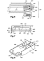
- the joining the connector portion 210 with a contact zone the complementary module can be done according to a plan vertical, called contact plane or joining plane, ie by moving the ballast 202 in a horizontal direction towards the illuminating element 201, and not a vertical direction as was the case in the example described in This junction will be more particularly detailed in FIGS. 4.
- the space requirement in the sense of height which was previously the presence of several connector and connector counterparts in a horizontal junction plane, has disappeared. With such a new the overall height of a headlamp device incorporating a complementary module advantageously decreases.
- an organization of different conductive electrical connections which allows to be limited to the presence of a single connector counterpart 210.
- a first electrical connection 213 constituting an input beam, which transports from the outside of the projector device 200 to the counterpart connector 210, a set of power and control.
- This first electrical connection 213 enters the illuminating element 201 at an opening 214 to go to connect on the counterpart 210.
- a bypass at counterpart 210 provides a second electrical connection, in the form of an output beam, which allows to feed the light source 203.
- FIGS. 3 and 4 show two examples of realization of electrical connection between the complementary module 202 and the projector device 201.
- the connector counterpart 210 is floating on the portion 209 of the rear surface 208 of the illuminating element 201.
- a first seal 501 and a second seal 502 are disposed between the portion rear 209 and the counterpart 210.
- the role of the first seal 501 and the second seal 502 will be specified later.
- One end, accessible from outside the illuminating element 201, has an opening 303. In an upper part of the opening 303, a first set 304 of connectivity elements, and in a lower part of the opening 303, a second set 305 of elements of connectivity.
- a connector element is a connection element electric composed of one or more conductive elements, of the paw type metal, slightly deformable to let slip without too much a support, comprising a set of contact zones, in an opening in which said connector element is disposed; the deformation of the connector element is elastic so that it remains supported on the area of the support at which it is located, said zone corresponding preferably to a contact zone of the support.
- the opening 303 is intended to receive one end of the card 216.
- the least one set of electrical contact areas For examples illustrated, a first set of contact areas 306 and a second set of contact areas 307 are shown respectively on an upper part and on a lower part of the electronic card 216.
- Figures 3 and 4 being sectional views, they show only one unique element of connectivity and that a single contact zone of sets to which they belong.
- the sets of elements of connectivity are in fact made up of a juxtaposition of elements of identical connections, or of different types, arranged in the alignment of the visible connector element, parallel to the visible plane in Figures 3 and 4.
- the sets of contact areas consist of a juxtaposition of contact zones, preferably identical, arranged in alignment with the visible contact area, parallel to the plane visible in Figures 3 and 4.
- the first set of contact areas 306, disposed on the upper part of the card 216, is apparent from Figure 5.
- the different contact zones 306 and 307 are arranged directly on the electronic card 216, that is to say that the electrical contacts are laid bare on the surface of the electronic board 216. In some embodiments, they can be integrated into the initial thickness of the electronic card, in the manner of the contact of a chip in a smart card. So when the map electronics 216 is embedded in the opening 303 of the counterpart 210, the elements of connections are directly in contact with the different contact areas. Preferably, the relationship between the elements connectivity and contact areas is bijective, ie each contact area is affected by a single element of connection.
- each first zone of contact of the first set 306 of contact zones is connected electrically to a second contact zone of the second assembly 307 contact areas, the first contact zone and the second zone of contact contact being preferably located one above the other.
- the link between two electrically connected contact areas is ensured via via, or bridging, internal to the electronic card 216.
- a similar configuration is planned for the sets of elements of connectivity, where each first element of connectivity of the first set of connection elements 304 is electrically connected to a second element of connectivity of the second set 305 of elements of connectivity, the first element of connectivity and the second connector element being preferably located one above the other.
- Such an embodiment ensures a good quality of electrical connection between connector elements and contact areas.
- each zone of contact and the connection element with which it is associated may be carried out by means of an intermediate part 211, electrically conductor, composed for example of a first set of legs of contact 308 and a second set of contact tabs 309, the tabs the same set being arranged in alignment with the contact tab visible, parallel to the plane visible in Figure 5. It is expected a contact tab by contact area.
- the two sets of legs are join at the level of a holding rod 310 which is intended to be inserted between the first set of connection elements 304 and the second set of connection elements 305 so as to ensure the electrical contact between the contact areas and the connection elements appropriate.
- Means cooperating to center all the contact zones compared to all the elements of connectivity when the card electronics is embedded in the counterpart are provided in the invention.
- Such means may in particular involve one or several guide pins 311 on counterpart 210 intended to come fit into a suitable opening 312, visible in Figure 5.
- a screw 300 in addition to various elements already present in FIG. represented a screw 300, preferably self-tapping, which, after having been introduced into a fastener located on the lower part of the ballast 202, is inserted in part 209 of the rear face, at the level of the recess 206 of the illuminating element 201 (shown in hatched lines) and the lateral part of the ballast 202 (shown in gray) serving as a plane of junction.
- the junction constituted by the screw 300 and the threaded bore 301 is preferably arranged centrally in width, as is visible on the figure 8. It is arranged under the bond which is established between the counterpart connector 210 and the set of contact areas.
- the head of the screw 300 comes directly, without the screw is inserted into a fastener, press a part protruding ballast 202 to maintain it on the illuminating element 201.
- a self-centering device of the set of elements of connectivity on the set of contact areas is planned: it appears at the Figure 8 in the form of two centering pins 500 arranged on the counterpart 210; these centering pins are intended to orient correctly the set of contact zones towards the connectivity elements counterpart 210 when the illuminating element 201 and the ballast 202 fit one into the other.
- the centering pins can be arranged on the module 202, or be replaced by chamfers arranged on the ballast 202 and / or the illuminating element 201.
- the screw 300 could be replaced by another mechanical means of fixation, for example a thrust spring which would be disposed behind the ballast 202 and which would exert on him a horizontal push to maintain operational the connection between the set of contact areas and the set of connection elements.
- a thrust spring which would be disposed behind the ballast 202 and which would exert on him a horizontal push to maintain operational the connection between the set of contact areas and the set of connection elements.
- 400 or slideways, visible in FIGS. 7 and 8, are provided on the illuminating element 201 at the recess 206. They are intended for guide, with a minimum of play, the horizontal translation movement of the ballast 202 when installed in the device 200, in order to facilitate mounting. 401 recesses, or protruding elements, of a size adequate to enter the guide rails 400, are provided for this purpose on the side walls of the ballast 202.
- the guide rails 400 play also a support role of the ballast 202 which can allow the use of a single screw 300.
- the guiding slides 400 may be arranged on a any face of the illuminating element 201 or the complementary module 202, possibly at the level of the recess 206 when it exists.
- a protruding element 401 slides along a slide of 400, it reaches a blocking position, for example by abutment mechanical, which corresponds to the final position of the add-on module, that is, its commissioning position.
- abutment mechanical which corresponds to the final position of the add-on module, that is, its commissioning position.
- the assembly of contact areas is properly embedded in the set of elements of connectors, ie the mechanical stop and the electrical connection are made at the same time. So that the connection electrical supply is satisfactory, the various means of centering can be arranged so that they also act at that moment.
- the guiding slides 400 are arranged inside the same the illuminating element 201, the complementary module then being intended to be contained in the illuminating element 201, which has an advantage in terms of sealing device according to the invention.
- the guiding rails 400 shrink gradually, so as to slow down by friction and then stop from the blocking position, the progression of the protruding elements 401.
- the protruding elements 401 can thus be blocked in the guide rails 400, thus able to maintain the module complementary 202 on the illuminating element 201 without using means of additional fixation.
- the first seal 501 of the lip seal type, already visible in FIGS. 4, and which appears in FIGS. 6 and 8, is arranged in the recess 206 for come wrap the ballast 202 at its front face, thus making Sealing the projector device 200 relative to the outside world.
- the first seal 501 can end with a membrane 502, visible by example in Figure 6, which ensures the seal between the ballast 202 and the connector against 210.
- This membrane 502 could take the shape of a second seal, dissociated from the first seal 501, which would prevent any infiltration of liquid between the ballast 202 and the illuminating element 201 at level of the fastening with play of the counterpart 210 on the illuminating element 201.
Landscapes
- Engineering & Computer Science (AREA)
- Mechanical Engineering (AREA)
- General Engineering & Computer Science (AREA)
- Non-Portable Lighting Devices Or Systems Thereof (AREA)
Applications Claiming Priority (2)
| Application Number | Priority Date | Filing Date | Title |
|---|---|---|---|
| FR0301570A FR2850729B1 (fr) | 2003-02-04 | 2003-02-04 | Dispositif projecteur equipe d'un module complementaire encastrable pour vehicule automobile |
| FR0301570 | 2003-02-04 |
Publications (3)
| Publication Number | Publication Date |
|---|---|
| EP1445533A2 true EP1445533A2 (de) | 2004-08-11 |
| EP1445533A3 EP1445533A3 (de) | 2008-10-29 |
| EP1445533B1 EP1445533B1 (de) | 2014-12-10 |
Family
ID=32606035
Family Applications (1)
| Application Number | Title | Priority Date | Filing Date |
|---|---|---|---|
| EP04290248.6A Expired - Lifetime EP1445533B1 (de) | 2003-02-04 | 2004-01-30 | Beleuchtungs- oder Signalisierungsvorrichtung für Kraftfahrzeug mit Einbau-Zusatzmodul |
Country Status (5)
| Country | Link |
|---|---|
| US (1) | US7222990B2 (de) |
| EP (1) | EP1445533B1 (de) |
| JP (1) | JP4554225B2 (de) |
| ES (1) | ES2532367T3 (de) |
| FR (1) | FR2850729B1 (de) |
Cited By (2)
| Publication number | Priority date | Publication date | Assignee | Title |
|---|---|---|---|---|
| FR3102644A1 (fr) * | 2019-10-29 | 2021-04-30 | Psa Automobiles Sa | Dispositif de support et de connexion d’une carte électronique pour le pilotage d’un module d’éclairage ou de signalisation de véhicule automobile |
| FR3139772A1 (fr) * | 2022-09-20 | 2024-03-22 | Psa Automobiles Sa | Bloc optique pour véhicule automobile doté de moyens de connexion électrique simplifiés |
Families Citing this family (10)
| Publication number | Priority date | Publication date | Assignee | Title |
|---|---|---|---|---|
| FR2843445B1 (fr) | 2002-08-08 | 2005-05-27 | Valeo Vision | Dispositif projecteur equipe d'un module complementaire pour vehicule automobile |
| FR2852381B1 (fr) * | 2003-03-14 | 2005-05-27 | Valeo Vision | Dispositif de blindage pour une connexion entre un projecteur et un module complementaire |
| JP4572796B2 (ja) * | 2004-11-11 | 2010-11-04 | 株式会社デンソー | 放電灯点灯装置 |
| FR2922714B1 (fr) * | 2007-10-19 | 2010-03-12 | Valeo Vision | Dispositif d'alimentation electrique pour une lampe a decharge comportant un blindage de ballast et un blindage de faisceau raccordes en parllele a un potentiel commun |
| US8070338B2 (en) * | 2008-04-07 | 2011-12-06 | General Electric Company | Three-mode integrated headlamp |
| EP2793317B1 (de) * | 2013-04-15 | 2016-03-02 | Siemens Aktiengesellschaft | Steckverbinder |
| US9086203B2 (en) * | 2013-11-06 | 2015-07-21 | GM Global Technology Operations LLC | Sealed bulb connector system for a headlamp assembly |
| DE102017106948A1 (de) * | 2017-03-31 | 2018-10-04 | HELLA GmbH & Co. KGaA | Lichtmodul für einen Scheinwerfer eines Fahrzeugs mit einem digital ansteuerbaren Lichtverteilungsmittel, insbesondere LCD-Scheinwerfer |
| JP2018206724A (ja) * | 2017-06-09 | 2018-12-27 | 株式会社小糸製作所 | 光源モジュール |
| KR102512377B1 (ko) * | 2021-08-10 | 2023-03-21 | 현대모비스 주식회사 | 엘이디 드라이버 모듈 및 이를 포함하는 차량 |
Family Cites Families (52)
| Publication number | Priority date | Publication date | Assignee | Title |
|---|---|---|---|---|
| GB1519150A (en) * | 1974-12-14 | 1978-07-26 | Lucas Electrical Ltd | Lamp assembly |
| US4182532A (en) | 1978-02-01 | 1980-01-08 | Walker Frank S Sr | Vehicle roof support member |
| US4674015A (en) * | 1986-05-05 | 1987-06-16 | Smith Daniel R | Fluorescent light fixture with removable ballast |
| US5198962A (en) * | 1989-08-03 | 1993-03-30 | Tyson Glenn M | Lighting system |
| JP2592005B2 (ja) * | 1990-05-18 | 1997-03-19 | 株式会社小糸製作所 | 車輌用前照灯 |
| GB2249825B (en) * | 1990-10-15 | 1994-06-22 | Koito Mfg Co Ltd | Vehicular headlamp |
| US5343370A (en) * | 1990-10-23 | 1994-08-30 | Koito Manufacturing Co., Ltd. | Motor vehicle headlamp |
| JP2768870B2 (ja) * | 1991-08-05 | 1998-06-25 | 株式会社小糸製作所 | バラスト回路と点灯回路間のコード接続構造 |
| US5107405A (en) * | 1991-08-20 | 1992-04-21 | Koito Manufacturing Co., Ltd. | Motor vehicle headlamp |
| DE4310307B4 (de) * | 1993-03-30 | 2004-10-14 | Robert Bosch Gmbh | Scheinwerfer für Fahrzeuge |
| JP2772323B2 (ja) * | 1993-04-28 | 1998-07-02 | 矢崎総業株式会社 | シールドコネクタ用端子およびシールドコネクタ |
| DE4334721B4 (de) * | 1993-10-12 | 2005-06-23 | Automotive Lighting Reutlingen Gmbh | Scheinwerfer für Fahrzeuge |
| JP2828584B2 (ja) * | 1993-12-27 | 1998-11-25 | 株式会社小糸製作所 | 自動車用ヘッドランプ |
| JP3062912B2 (ja) * | 1994-04-26 | 2000-07-12 | 株式会社小糸製作所 | 車輌用灯具 |
| JP3010518B2 (ja) * | 1994-06-28 | 2000-02-21 | 株式会社小糸製作所 | 車輌用前照灯 |
| DE4445223A1 (de) * | 1994-12-17 | 1996-06-20 | Bosch Gmbh Robert | Scheinwerfer für Fahrzeuge |
| JP3061248B2 (ja) * | 1995-01-20 | 2000-07-10 | 株式会社小糸製作所 | 自動車用ヘッドランプ |
| DE19504112A1 (de) * | 1995-02-08 | 1996-08-22 | Wila Leuchten Gmbh | Anschlußeinheit für einseitig gesockelte Entladungslampen |
| US6066921A (en) * | 1995-02-28 | 2000-05-23 | Matsushita Electric Works, Ltd. | Discharge lamp lighting device |
| JPH09129379A (ja) * | 1995-11-06 | 1997-05-16 | Koito Mfg Co Ltd | 放電灯点灯装置 |
| JP3195215B2 (ja) | 1995-12-28 | 2001-08-06 | 株式会社小糸製作所 | 自動車用ヘッドランプ |
| US5879073A (en) * | 1996-01-29 | 1999-03-09 | Koito Manufacturing Co., Ltd. | Vehicular lamp having discharge bulb |
| JP3159078B2 (ja) * | 1996-08-30 | 2001-04-23 | 株式会社デンソー | 高圧放電灯装置 |
| DE19644995A1 (de) * | 1996-10-31 | 1998-05-07 | Mannesmann Vdo Ag | Anzeigeinstrument mit einem beleuchtbaren Anzeigefeld |
| DE19649722A1 (de) * | 1996-11-30 | 1998-06-04 | Reitter & Schefenacker Gmbh | Heckleuchte für Kraftfahrzeuge |
| JPH10261301A (ja) * | 1997-01-16 | 1998-09-29 | Honda Motor Co Ltd | 車両用前照灯 |
| JPH10208505A (ja) * | 1997-01-24 | 1998-08-07 | Koito Mfg Co Ltd | 車輌用前照灯 |
| GB2324599A (en) * | 1997-04-22 | 1998-10-28 | Ford Motor Co | Looped light pipe illuminator for illuminating dials etc. |
| FR2769072B1 (fr) * | 1997-09-26 | 1999-12-24 | Valeo Vision | Projecteur de vehicule automobile equipe d'une lampe a decharge et de moyens perfectionnes de blindage electromagnetique |
| JP3737295B2 (ja) * | 1997-11-11 | 2006-01-18 | 株式会社小糸製作所 | 車両用前照灯 |
| US6043614A (en) * | 1998-03-06 | 2000-03-28 | Osram Sylvania Inc. | Alternating current hid lamp with magnetic deflection |
| FR2783593B1 (fr) | 1998-09-21 | 2000-12-29 | Valeo Vision | Projecteur de vehicule automobile equipe d'une lampe a decharge et de moyens perfectionnes de blindage electromagnetique |
| US6102550A (en) * | 1999-02-16 | 2000-08-15 | Photronix, Llc | Bracket assembly for fluorescent lighting fixture having removable, high-frequency power output ballast |
| JP3854421B2 (ja) * | 1999-02-23 | 2006-12-06 | 株式会社小糸製作所 | 放電バルブを有する車両用灯具 |
| JP2000251511A (ja) * | 1999-03-03 | 2000-09-14 | Koito Mfg Co Ltd | 車両用灯具 |
| FR2795691B1 (fr) | 1999-07-02 | 2001-08-17 | Valeo Vision | Projecteur de vehicule automobile equipe d'une lampe a decharge et de moyens de blindage electromagnetique perfectionnes |
| DE19941538A1 (de) | 1999-09-01 | 2001-03-15 | Hella Kg Hueck & Co | Gerät zur Aufnahme einer Gasentladungslampe eines Fahrzeug-Scheinwerfers |
| JP3893812B2 (ja) * | 1999-09-30 | 2007-03-14 | 松下電工株式会社 | 照明装置 |
| EP1598592B1 (de) * | 1999-09-30 | 2008-07-23 | Matsushita Electric Works, Ltd. | Beleuchtungseinrichtung |
| JP3720224B2 (ja) | 1999-10-19 | 2005-11-24 | 株式会社小糸製作所 | 車両用前照灯 |
| AU2001278022A1 (en) | 2000-08-01 | 2002-02-13 | Osram Sylvania Inc. | Aperture lamp, aperture lamp housing and aperture lamp assembly |
| DE10193456T1 (de) | 2000-08-18 | 2002-10-24 | Mitsubishi Electric Corp | Abgeschirmter Draht, Verfahren zur Herstellung eines abgeschirmten Drahtes und Leuchtvorrichtung für eine Entladungslampe, welche den abgeschirmten Draht verwendet |
| JP2002150830A (ja) | 2000-11-07 | 2002-05-24 | Denso Corp | 放電灯装置 |
| JP2002170407A (ja) | 2000-12-01 | 2002-06-14 | Koito Mfg Co Ltd | 車両用前照灯 |
| JP3928691B2 (ja) | 2000-12-06 | 2007-06-13 | 株式会社小糸製作所 | 車輌用前照灯 |
| FR2826099B1 (fr) | 2001-06-18 | 2003-12-19 | Valeo Vision | Dispositif d'eclairage ou de signalisation d'aspect ameliore pour vehicule automobile |
| DE10137350B4 (de) * | 2001-07-31 | 2006-10-05 | Hella Kgaa Hueck & Co. | Beleuchtungseinrichtung |
| US6672747B2 (en) | 2001-08-07 | 2004-01-06 | Denso Corporation | Vehicle headlamp having removable lighting control unit |
| JP3931092B2 (ja) | 2002-02-08 | 2007-06-13 | 株式会社小糸製作所 | 車輌用前照灯 |
| JP4000269B2 (ja) | 2002-03-22 | 2007-10-31 | 株式会社小糸製作所 | 車輌用前照灯 |
| FR2843445B1 (fr) | 2002-08-08 | 2005-05-27 | Valeo Vision | Dispositif projecteur equipe d'un module complementaire pour vehicule automobile |
| FR2852381B1 (fr) * | 2003-03-14 | 2005-05-27 | Valeo Vision | Dispositif de blindage pour une connexion entre un projecteur et un module complementaire |
-
2003
- 2003-02-04 FR FR0301570A patent/FR2850729B1/fr not_active Expired - Fee Related
-
2004
- 2004-01-30 ES ES04290248.6T patent/ES2532367T3/es not_active Expired - Lifetime
- 2004-01-30 EP EP04290248.6A patent/EP1445533B1/de not_active Expired - Lifetime
- 2004-02-03 US US10/771,991 patent/US7222990B2/en not_active Expired - Lifetime
- 2004-02-04 JP JP2004027598A patent/JP4554225B2/ja not_active Expired - Fee Related
Cited By (3)
| Publication number | Priority date | Publication date | Assignee | Title |
|---|---|---|---|---|
| FR3102644A1 (fr) * | 2019-10-29 | 2021-04-30 | Psa Automobiles Sa | Dispositif de support et de connexion d’une carte électronique pour le pilotage d’un module d’éclairage ou de signalisation de véhicule automobile |
| EP3815972A1 (de) * | 2019-10-29 | 2021-05-05 | PSA Automobiles SA | Träger- und vrebindungsvorrichtung einer elektronischen karte für die steuerung eines licht- oder signalisierungsmoduls eines kraftfahrzeugs |
| FR3139772A1 (fr) * | 2022-09-20 | 2024-03-22 | Psa Automobiles Sa | Bloc optique pour véhicule automobile doté de moyens de connexion électrique simplifiés |
Also Published As
| Publication number | Publication date |
|---|---|
| JP2004241386A (ja) | 2004-08-26 |
| FR2850729A1 (fr) | 2004-08-06 |
| FR2850729B1 (fr) | 2006-03-17 |
| US20040184281A1 (en) | 2004-09-23 |
| US7222990B2 (en) | 2007-05-29 |
| ES2532367T3 (es) | 2015-03-26 |
| JP4554225B2 (ja) | 2010-09-29 |
| EP1445533A3 (de) | 2008-10-29 |
| EP1445533B1 (de) | 2014-12-10 |
Similar Documents
| Publication | Publication Date | Title |
|---|---|---|
| EP1445533B1 (de) | Beleuchtungs- oder Signalisierungsvorrichtung für Kraftfahrzeug mit Einbau-Zusatzmodul | |
| EP2775197B1 (de) | Vorrichtung zur Beleuchtung und/oder Signalisierung für ein Kraftfahrzeug, die einen Lichtwellenleiter umfasst | |
| EP1388711B1 (de) | Beleuchtungs- oder Signalleuchte mit Zusatzmodul für Kraftfahrzeug | |
| FR3056702B1 (fr) | Module lumineux avec dispositif de pilotage integre | |
| EP4065882A1 (de) | Optisches element und lichtmodul eines kraftfahrzeuges mit einem solchen optischen element | |
| FR2922167A1 (fr) | Module d'eclairage pour un phare ou eclairage d'un vehicule automobile. | |
| FR3026468B1 (fr) | Dispositif a composant semi-conducteur monte sur un dissipateur de chaleur, procede de montage, et dispositif d'eclairage pour vehicule automobile comportant un tel dispositif | |
| FR3056699B1 (fr) | Module lumineux et dispositif lumineux pour vehicule auto-mobile comportant un tel module lumineux | |
| EP0430792B1 (de) | Verbesserung für Multiplex-Steuergeräte für eine Anordnung elektrischer Elemente in einem Kraftfahrzeug | |
| EP1839946B1 (de) | Beleuchtungsvorrichtung für elektrischen Zigarrenanzünder oder multi-funktionelle elektrische Steckdose | |
| EP1516777B1 (de) | Beleuchtungsvorrichtung für elektrischen Zigarrenanzünder oder multi-funktionelle elektrische Steckdose | |
| EP1458061B1 (de) | Abschirmvorrichtung für eine Verbindung zwischen einem Scheinwerfer und einem komplimentären Modul | |
| EP0624495B1 (de) | Elektrische Baugruppe für die Multiplexsteuerung einer Beleuchtungs- oder Signaleinrichtung an Kraftfahrzeugen | |
| EP3270052A1 (de) | Halterung eines leuchtmittels für kraftfahrzeug | |
| FR2996629A1 (fr) | Module d'eclairage a lentille pilotee electriquement | |
| FR3078559A1 (fr) | Dispositif d’eclairage de vehicule, a masque a nervures de limitation de sortie de photons de guides de lumiere. | |
| EP3383150B1 (de) | Stromversorgungsvorrichtung für mindestens eine led und mindestens ein elektronisches bauelement, mit einer ein insert enthaltenden stromversorgungssteuerschaltung | |
| FR2786145A1 (fr) | Structure de feux pour vehicule automobile | |
| FR2867837A1 (fr) | Dispositif projecteur equipe d'une carte de controle electronique pour vehicule automobile | |
| FR2685439A1 (fr) | Projecteur de vehicule automobile presentant une disposition de circuit electronique perfectionnee. | |
| FR3105360A1 (fr) | Module lumineux d’un véhicule automobile comportant deux sources lumineuses | |
| EP3270040B1 (de) | Leuchtmodul für kraftfahrzeug | |
| FR2842479A1 (fr) | Dispositif projecteur avec carte de controle electronique pour vehicule automobile | |
| WO2011131894A1 (fr) | Douille a double verrouillage pour ampoule electrique | |
| EP2051574A1 (de) | Vorrichtung zur Stromversorgung einer Leuchtstofflampe, die eine Abschirmung des Vorschaltgeräts umfasst |
Legal Events
| Date | Code | Title | Description |
|---|---|---|---|
| PUAI | Public reference made under article 153(3) epc to a published international application that has entered the european phase |
Free format text: ORIGINAL CODE: 0009012 |
|
| AK | Designated contracting states |
Kind code of ref document: A2 Designated state(s): AT BE BG CH CY CZ DE DK EE ES FI FR GB GR HU IE IT LI LU MC NL PT RO SE SI SK TR |
|
| AX | Request for extension of the european patent |
Extension state: AL LT LV MK |
|
| RIN1 | Information on inventor provided before grant (corrected) |
Inventor name: MYOTTE, DAVID Inventor name: NICOLAI, JEAN-MARC Inventor name: DUARTE, MARC |
|
| PUAL | Search report despatched |
Free format text: ORIGINAL CODE: 0009013 |
|
| AK | Designated contracting states |
Kind code of ref document: A3 Designated state(s): AT BE BG CH CY CZ DE DK EE ES FI FR GB GR HU IE IT LI LU MC NL PT RO SE SI SK TR |
|
| AX | Request for extension of the european patent |
Extension state: AL LT LV MK |
|
| 17P | Request for examination filed |
Effective date: 20090420 |
|
| 17Q | First examination report despatched |
Effective date: 20090609 |
|
| AKX | Designation fees paid |
Designated state(s): AT BE BG CH CY CZ DE DK EE ES FI FR GB GR HU IE IT LI LU MC NL PT RO SE SI SK TR |
|
| RIC1 | Information provided on ipc code assigned before grant |
Ipc: F21V 19/00 20060101AFI20130624BHEP Ipc: H01R 33/76 20060101ALI20130624BHEP Ipc: F21V 23/02 20060101ALI20130624BHEP |
|
| GRAP | Despatch of communication of intention to grant a patent |
Free format text: ORIGINAL CODE: EPIDOSNIGR1 |
|
| INTG | Intention to grant announced |
Effective date: 20131211 |
|
| GRAS | Grant fee paid |
Free format text: ORIGINAL CODE: EPIDOSNIGR3 |
|
| GRAP | Despatch of communication of intention to grant a patent |
Free format text: ORIGINAL CODE: EPIDOSNIGR1 |
|
| INTG | Intention to grant announced |
Effective date: 20140715 |
|
| GRAA | (expected) grant |
Free format text: ORIGINAL CODE: 0009210 |
|
| AK | Designated contracting states |
Kind code of ref document: B1 Designated state(s): AT BE BG CH CY CZ DE DK EE ES FI FR GB GR HU IE IT LI LU MC NL PT RO SE SI SK TR |
|
| REG | Reference to a national code |
Ref country code: GB Ref legal event code: FG4D Free format text: NOT ENGLISH |
|
| REG | Reference to a national code |
Ref country code: CH Ref legal event code: EP |
|
| REG | Reference to a national code |
Ref country code: IE Ref legal event code: FG4D Free format text: LANGUAGE OF EP DOCUMENT: FRENCH |
|
| REG | Reference to a national code |
Ref country code: AT Ref legal event code: REF Ref document number: 700848 Country of ref document: AT Kind code of ref document: T Effective date: 20150115 |
|
| REG | Reference to a national code |
Ref country code: DE Ref legal event code: R096 Ref document number: 602004046294 Country of ref document: DE Effective date: 20150122 |
|
| REG | Reference to a national code |
Ref country code: RO Ref legal event code: EPE |
|
| REG | Reference to a national code |
Ref country code: NL Ref legal event code: T3 |
|
| REG | Reference to a national code |
Ref country code: ES Ref legal event code: FG2A Ref document number: 2532367 Country of ref document: ES Kind code of ref document: T3 Effective date: 20150326 |
|
| REG | Reference to a national code |
Ref country code: SE Ref legal event code: TRGR |
|
| PG25 | Lapsed in a contracting state [announced via postgrant information from national office to epo] |
Ref country code: FI Free format text: LAPSE BECAUSE OF FAILURE TO SUBMIT A TRANSLATION OF THE DESCRIPTION OR TO PAY THE FEE WITHIN THE PRESCRIBED TIME-LIMIT Effective date: 20141210 |
|
| PG25 | Lapsed in a contracting state [announced via postgrant information from national office to epo] |
Ref country code: GR Free format text: LAPSE BECAUSE OF FAILURE TO SUBMIT A TRANSLATION OF THE DESCRIPTION OR TO PAY THE FEE WITHIN THE PRESCRIBED TIME-LIMIT Effective date: 20150311 |
|
| REG | Reference to a national code |
Ref country code: SK Ref legal event code: T3 Ref document number: E 18312 Country of ref document: SK |
|
| PG25 | Lapsed in a contracting state [announced via postgrant information from national office to epo] |
Ref country code: EE Free format text: LAPSE BECAUSE OF FAILURE TO SUBMIT A TRANSLATION OF THE DESCRIPTION OR TO PAY THE FEE WITHIN THE PRESCRIBED TIME-LIMIT Effective date: 20141210 Ref country code: PT Free format text: LAPSE BECAUSE OF FAILURE TO SUBMIT A TRANSLATION OF THE DESCRIPTION OR TO PAY THE FEE WITHIN THE PRESCRIBED TIME-LIMIT Effective date: 20150410 |
|
| REG | Reference to a national code |
Ref country code: CH Ref legal event code: PL |
|
| PG25 | Lapsed in a contracting state [announced via postgrant information from national office to epo] |
Ref country code: LU Free format text: LAPSE BECAUSE OF FAILURE TO SUBMIT A TRANSLATION OF THE DESCRIPTION OR TO PAY THE FEE WITHIN THE PRESCRIBED TIME-LIMIT Effective date: 20150130 |
|
| REG | Reference to a national code |
Ref country code: DE Ref legal event code: R097 Ref document number: 602004046294 Country of ref document: DE |
|
| PG25 | Lapsed in a contracting state [announced via postgrant information from national office to epo] |
Ref country code: MC Free format text: LAPSE BECAUSE OF FAILURE TO SUBMIT A TRANSLATION OF THE DESCRIPTION OR TO PAY THE FEE WITHIN THE PRESCRIBED TIME-LIMIT Effective date: 20141210 |
|
| PLBE | No opposition filed within time limit |
Free format text: ORIGINAL CODE: 0009261 |
|
| STAA | Information on the status of an ep patent application or granted ep patent |
Free format text: STATUS: NO OPPOSITION FILED WITHIN TIME LIMIT |
|
| PG25 | Lapsed in a contracting state [announced via postgrant information from national office to epo] |
Ref country code: LI Free format text: LAPSE BECAUSE OF NON-PAYMENT OF DUE FEES Effective date: 20150131 Ref country code: DK Free format text: LAPSE BECAUSE OF FAILURE TO SUBMIT A TRANSLATION OF THE DESCRIPTION OR TO PAY THE FEE WITHIN THE PRESCRIBED TIME-LIMIT Effective date: 20141210 Ref country code: CH Free format text: LAPSE BECAUSE OF NON-PAYMENT OF DUE FEES Effective date: 20150131 |
|
| REG | Reference to a national code |
Ref country code: IE Ref legal event code: MM4A |
|
| 26N | No opposition filed |
Effective date: 20150911 |
|
| PG25 | Lapsed in a contracting state [announced via postgrant information from national office to epo] |
Ref country code: IE Free format text: LAPSE BECAUSE OF NON-PAYMENT OF DUE FEES Effective date: 20150130 |
|
| REG | Reference to a national code |
Ref country code: FR Ref legal event code: PLFP Year of fee payment: 13 |
|
| REG | Reference to a national code |
Ref country code: AT Ref legal event code: UEP Ref document number: 700848 Country of ref document: AT Kind code of ref document: T Effective date: 20141210 |
|
| PG25 | Lapsed in a contracting state [announced via postgrant information from national office to epo] |
Ref country code: SI Free format text: LAPSE BECAUSE OF FAILURE TO SUBMIT A TRANSLATION OF THE DESCRIPTION OR TO PAY THE FEE WITHIN THE PRESCRIBED TIME-LIMIT Effective date: 20141210 |
|
| REG | Reference to a national code |
Ref country code: FR Ref legal event code: PLFP Year of fee payment: 14 |
|
| PG25 | Lapsed in a contracting state [announced via postgrant information from national office to epo] |
Ref country code: BG Free format text: LAPSE BECAUSE OF FAILURE TO SUBMIT A TRANSLATION OF THE DESCRIPTION OR TO PAY THE FEE WITHIN THE PRESCRIBED TIME-LIMIT Effective date: 20141210 Ref country code: HU Free format text: LAPSE BECAUSE OF FAILURE TO SUBMIT A TRANSLATION OF THE DESCRIPTION OR TO PAY THE FEE WITHIN THE PRESCRIBED TIME-LIMIT; INVALID AB INITIO Effective date: 20040130 |
|
| PG25 | Lapsed in a contracting state [announced via postgrant information from national office to epo] |
Ref country code: CY Free format text: LAPSE BECAUSE OF FAILURE TO SUBMIT A TRANSLATION OF THE DESCRIPTION OR TO PAY THE FEE WITHIN THE PRESCRIBED TIME-LIMIT Effective date: 20141210 |
|
| PGFP | Annual fee paid to national office [announced via postgrant information from national office to epo] |
Ref country code: RO Payment date: 20171220 Year of fee payment: 15 Ref country code: SK Payment date: 20171215 Year of fee payment: 15 |
|
| REG | Reference to a national code |
Ref country code: FR Ref legal event code: PLFP Year of fee payment: 15 |
|
| PGFP | Annual fee paid to national office [announced via postgrant information from national office to epo] |
Ref country code: SE Payment date: 20180122 Year of fee payment: 15 |
|
| REG | Reference to a national code |
Ref country code: SK Ref legal event code: MM4A Ref document number: E 18312 Country of ref document: SK Effective date: 20190130 |
|
| PG25 | Lapsed in a contracting state [announced via postgrant information from national office to epo] |
Ref country code: SE Free format text: LAPSE BECAUSE OF NON-PAYMENT OF DUE FEES Effective date: 20190131 Ref country code: RO Free format text: LAPSE BECAUSE OF NON-PAYMENT OF DUE FEES Effective date: 20190130 Ref country code: SK Free format text: LAPSE BECAUSE OF NON-PAYMENT OF DUE FEES Effective date: 20190130 |
|
| PGFP | Annual fee paid to national office [announced via postgrant information from national office to epo] |
Ref country code: CZ Payment date: 20191219 Year of fee payment: 17 |
|
| PGFP | Annual fee paid to national office [announced via postgrant information from national office to epo] |
Ref country code: GB Payment date: 20200131 Year of fee payment: 17 Ref country code: AT Payment date: 20191223 Year of fee payment: 17 Ref country code: IT Payment date: 20200114 Year of fee payment: 17 Ref country code: ES Payment date: 20200227 Year of fee payment: 17 |
|
| PGFP | Annual fee paid to national office [announced via postgrant information from national office to epo] |
Ref country code: TR Payment date: 20200120 Year of fee payment: 17 |
|
| PGFP | Annual fee paid to national office [announced via postgrant information from national office to epo] |
Ref country code: NL Payment date: 20201214 Year of fee payment: 18 |
|
| PGFP | Annual fee paid to national office [announced via postgrant information from national office to epo] |
Ref country code: FR Payment date: 20210128 Year of fee payment: 18 |
|
| PGFP | Annual fee paid to national office [announced via postgrant information from national office to epo] |
Ref country code: DE Payment date: 20210112 Year of fee payment: 18 Ref country code: BE Payment date: 20210114 Year of fee payment: 18 |
|
| REG | Reference to a national code |
Ref country code: AT Ref legal event code: MM01 Ref document number: 700848 Country of ref document: AT Kind code of ref document: T Effective date: 20210130 |
|
| GBPC | Gb: european patent ceased through non-payment of renewal fee |
Effective date: 20210130 |
|
| PG25 | Lapsed in a contracting state [announced via postgrant information from national office to epo] |
Ref country code: AT Free format text: LAPSE BECAUSE OF NON-PAYMENT OF DUE FEES Effective date: 20210130 Ref country code: CZ Free format text: LAPSE BECAUSE OF NON-PAYMENT OF DUE FEES Effective date: 20210130 |
|
| PG25 | Lapsed in a contracting state [announced via postgrant information from national office to epo] |
Ref country code: GB Free format text: LAPSE BECAUSE OF NON-PAYMENT OF DUE FEES Effective date: 20210130 |
|
| REG | Reference to a national code |
Ref country code: ES Ref legal event code: FD2A Effective date: 20220427 |
|
| PG25 | Lapsed in a contracting state [announced via postgrant information from national office to epo] |
Ref country code: IT Free format text: LAPSE BECAUSE OF NON-PAYMENT OF DUE FEES Effective date: 20210130 |
|
| PG25 | Lapsed in a contracting state [announced via postgrant information from national office to epo] |
Ref country code: ES Free format text: LAPSE BECAUSE OF NON-PAYMENT OF DUE FEES Effective date: 20210131 |
|
| REG | Reference to a national code |
Ref country code: DE Ref legal event code: R119 Ref document number: 602004046294 Country of ref document: DE |
|
| REG | Reference to a national code |
Ref country code: NL Ref legal event code: MM Effective date: 20220201 |
|
| REG | Reference to a national code |
Ref country code: BE Ref legal event code: MM Effective date: 20220131 |
|
| PG25 | Lapsed in a contracting state [announced via postgrant information from national office to epo] |
Ref country code: NL Free format text: LAPSE BECAUSE OF NON-PAYMENT OF DUE FEES Effective date: 20220201 Ref country code: DE Free format text: LAPSE BECAUSE OF NON-PAYMENT OF DUE FEES Effective date: 20220802 |
|
| PG25 | Lapsed in a contracting state [announced via postgrant information from national office to epo] |
Ref country code: FR Free format text: LAPSE BECAUSE OF NON-PAYMENT OF DUE FEES Effective date: 20220131 Ref country code: BE Free format text: LAPSE BECAUSE OF NON-PAYMENT OF DUE FEES Effective date: 20220131 |
|
| PG25 | Lapsed in a contracting state [announced via postgrant information from national office to epo] |
Ref country code: TR Free format text: LAPSE BECAUSE OF NON-PAYMENT OF DUE FEES Effective date: 20210130 |