EP1445557A2 - Eiserzeuger - Google Patents
Eiserzeuger Download PDFInfo
- Publication number
- EP1445557A2 EP1445557A2 EP03024744A EP03024744A EP1445557A2 EP 1445557 A2 EP1445557 A2 EP 1445557A2 EP 03024744 A EP03024744 A EP 03024744A EP 03024744 A EP03024744 A EP 03024744A EP 1445557 A2 EP1445557 A2 EP 1445557A2
- Authority
- EP
- European Patent Office
- Prior art keywords
- ice
- cam
- sensing
- lever
- storage tray
- Prior art date
- Legal status (The legal status is an assumption and is not a legal conclusion. Google has not performed a legal analysis and makes no representation as to the accuracy of the status listed.)
- Withdrawn
Links
Images


Classifications
-
- F—MECHANICAL ENGINEERING; LIGHTING; HEATING; WEAPONS; BLASTING
- F25—REFRIGERATION OR COOLING; COMBINED HEATING AND REFRIGERATION SYSTEMS; HEAT PUMP SYSTEMS; MANUFACTURE OR STORAGE OF ICE; LIQUEFACTION SOLIDIFICATION OF GASES
- F25C—PRODUCING, WORKING OR HANDLING ICE
- F25C1/00—Producing ice
- F25C1/22—Construction of moulds; Filling devices for moulds
- F25C1/24—Construction of moulds; Filling devices for moulds for refrigerators, e.g. freezing trays
-
- F—MECHANICAL ENGINEERING; LIGHTING; HEATING; WEAPONS; BLASTING
- F25—REFRIGERATION OR COOLING; COMBINED HEATING AND REFRIGERATION SYSTEMS; HEAT PUMP SYSTEMS; MANUFACTURE OR STORAGE OF ICE; LIQUEFACTION SOLIDIFICATION OF GASES
- F25C—PRODUCING, WORKING OR HANDLING ICE
- F25C5/00—Working or handling ice
- F25C5/18—Storing ice
- F25C5/182—Ice bins therefor
- F25C5/187—Ice bins therefor with ice level sensing means
-
- F—MECHANICAL ENGINEERING; LIGHTING; HEATING; WEAPONS; BLASTING
- F25—REFRIGERATION OR COOLING; COMBINED HEATING AND REFRIGERATION SYSTEMS; HEAT PUMP SYSTEMS; MANUFACTURE OR STORAGE OF ICE; LIQUEFACTION SOLIDIFICATION OF GASES
- F25C—PRODUCING, WORKING OR HANDLING ICE
- F25C1/00—Producing ice
- F25C1/10—Producing ice by using rotating or otherwise moving moulds
-
- F—MECHANICAL ENGINEERING; LIGHTING; HEATING; WEAPONS; BLASTING
- F25—REFRIGERATION OR COOLING; COMBINED HEATING AND REFRIGERATION SYSTEMS; HEAT PUMP SYSTEMS; MANUFACTURE OR STORAGE OF ICE; LIQUEFACTION SOLIDIFICATION OF GASES
- F25C—PRODUCING, WORKING OR HANDLING ICE
- F25C5/00—Working or handling ice
- F25C5/18—Storing ice
- F25C5/182—Ice bins therefor
- F25C5/185—Ice bins therefor with freezing trays
Definitions
- the present invention relates, in general, to ice makers and, more particularly, though not exclusively, to an ice maker capable of efficiently making and removing ice cubes.
- an ice maker is installed in a refrigerator or a vending machine to make ice cubes out of water which is supplied to the ice maker.
- a conventional ice maker includes drive and driven pulleys which are installed to be spaced apart from each other by a predetermined distance.
- An ice making conveyor is wrapped around the drive and driven pulleys, and is provided with a plurality of ice making parts to contain water therein.
- a heater is installed at a predetermined position in the ice making conveyor.
- the heater applies heat to the ice making parts which face downward, thus removing the ice cubes from the lower ice making parts.
- An ice storage tray is provided under the ice making conveyor to store the ice cubes removed from the ice making parts.
- the ice making conveyor is moved by the drive and driven pulleys to make the ice making parts having the ice cubes face downward. Thereafter, electricity is applied to the heater to generate heat. The ice cubes are removed from the ice making parts by the heat, prior to being stored in the ice storage tray.
- the conventional ice maker has a problem in that the ice maker is designed to continuously make ice cubes, thus an excessive number of ice cubes are made when the ice maker continues operations after a proper point of time. In this case, the ice cubes overflow the ice storage tray.
- an ice maker comprising: an ice making unit; an ice storage tray for receiving ice from the ice making unit; and an ice level sensing unit to sense a level of ice stored in the ice storage tray, thus shutting off electricity.
- the ice maker includes first and second pulleys which are installed to be spaced apart from each other, a drive unit which rotates the first and second pulleys, an ice making conveyor which is wrapped around the first and second pulleys and has a plurality of ice making parts concavely formed to contain water therein, and wherein the ice storage tray is provided under the ice making conveyor to store ice cubes dropping from the ice making parts.
- the ice level sensing unit may include a sensing lever which moves up and down in a see-saw manner, a cam which is rotated by a force transmitted from the drive unit to move the sensing lever up and down, and a switch which is pressed by the sensing lever to turn on or off the electricity.
- the sensing lever may comprise a bar of a predetermined length, the bar comprising a hinge part which is provided at a middle portion of the bar to allow the bar to move up and down relative to the hinge part, a sensing part which is provided at a first side of the bar around the hinge part to be supported by the ice cubes stored in the ice storage tray, and a lever part which is provided at a second side of the bar opposite to the sensing part and is operated by the force of the drive unit transmitted through the cam to move the bar up and down.
- the lever part may include, at an end thereof, a pressing part having a circular cross-section to be operated by the force of the drive unit transmitted through the cam, thus pressing the switch down.
- the cam is rotated by the force of the drive unit transmitted through the first and second pulleys which are rotated by the drive unit, with a projection provided at a predetermined portion of the cam to apply the force to the lever part according to a rotating angle of the cam.
- the switch suitably shuts off the electricity, when the switch is pressed down by the sensing lever over a predetermined period.
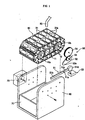
- an ice maker includes first and second pulleys 10a and 10b which are installed to be spaced apart from each other by a predetermined distance.
- a drive unit 20 rotates the first and second pulleys 10a and 10b.
- An ice making conveyor 30 is wrapped around the first and second pulleys 10a and 10b.
- the first pulley 10a comprises a drive pulley 10a which is rotated by a force transmitted from the drive unit 20.
- the second pulley 10b comprises a driven pulley 10b which is rotated by the force transmitted from the first pulley 10a through the ice making conveyor 30.
- a support bracket 11 Between the drive and driven pulleys 10a and 10b is provided a support bracket 11.
- the drive and driven pulleys 10a and 10b are installed at opposite ends of the support bracket 11 to be spaced apart from each other by a predetermined distance.
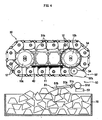
- the ice making conveyor 30 includes a plurality of tray cells 31 with concave ice making parts 31a.
- the tray cells 31 are hinged to each other to form the ice making conveyor 30 of a closed loop shape.
- Each of the ice making parts 31a is made of a metal, such as stainless steel, thus allowing heat to be easily transferred to each of the ice making parts 31a.
- the pulley's 10a, 10b, drive unit 20, ice making conveyor 30 and ice making parts 31a together comprise an ice making unit.
- An engaging projection 31b is projected from an inside portion of each of the tray cells 31 to be subject to the force transmitted from the drive pulley 10a. Further, a plurality of engaging holes 12 are provided on outer circumferential surfaces of the drive and driven pulleys 10a and 10b at regular intervals to engage with the engaging projections 31b. Thus, when the force is transmitted from the drive pulley 10a to the tray cells 31, via the engaging projections 31b and the engaging holes 12, the tray cells 31 rotate around the drive and driven pulleys 10a and 10b.
- the ice maker also includes a heater 40 (see, FIG. 2) to apply heat to the ice making parts 31a.
- the heater 40 is mounted to a lower portion of the support bracket 11 to apply heat to the tray cells 31 defining the ice making parts 31a which face downward.
- the support bracket 11 is mounted at both ends thereof to an interior of a cooling compartment to install the ice maker in the cooling compartment.
- a mounting bracket 60 is provided to hold both sides of the support bracket 11, thus supporting the ice making conveyor 30 in the cooling compartment.
- An ice storage tray 70 is provided under the ice making conveyor 30 to store ice cubes made from the ice making parts 31a.
- a water supply pipe 80 is provided above the ice making conveyor 30 to supply water to the tray cells 31.
- the ice maker includes an ice level sensing unit 50 to sense a level of the ice cubes which are stored in the ice storage tray 70. Once the level of the ice cubes sensed by the ice level sensing unit 50 has reached a predetermined level, the ice maker stops making the ice cubes.
- the ice level sensing unit 50 measures the level of the ice cubes stored in the ice storage tray 70, thus detecting an amount of the ice.
- the ice level sensing unit 50 includes a sensing lever 51, a cam 52, and a switch 53.
- the sensing lever 51 is hinged at a middle portion thereof to the mounting bracket 60 to move up and down in a see-saw manner.
- the cam 52 moves the sensing lever 51 in the see-saw manner.
- the switch 53 is pressed by the sensing lever 51 to turn on or off the electricity which is applied to the ice maker.
- the sensing lever 51 comprises a bar of a predetermined length.
- the bar includes a hinge part 51a which is hinged to the mounting bracket 60.
- a sensing part 51b is provided at a first side of the bar around the hinge part 51a to be supported by the ice cubes stored in the ice storage tray 70.
- a lever part 51c is provided at a second side of the bar which is opposite to the sensing part 51b, and is operated by the force of the drive unit 20 transmitted through the cam 52.
- a pressing part 51d At an end of the lever part 51c is provided a pressing part 51d to press the switch 53.
- the pressing part 51d has a circular cross-section so that the force of the drive unit 20 is easily transmitted from the cam 52 to the pressing part 51d.
- a projection part 52a is provided at a predetermined portion of the cam 52 to be eccentric from a center of rotation of the cam 52.
- the projection part 52a at specific angles transmits the force of the drive unit 20 to the pressing part 51d to move the pressing part 51d.
- the pressing part 51d periodically presses the switch 53 down.
- the cam 52 is rotated by the rotating force transmitted from the drive unit 20.
- the rotating force of the drive unit 20 is transmitted to the cam 52 through a pair of intermediate gears 54 connected to a shaft of the driven pulley 10b which is rotated by the ice making conveyor 30.
- the switch 53 is installed under the pressing part 51d of the sensing lever 51 to be pressed by the pressing part 51d which is moved downward by the cam 52.
- the switch 53 is kept pressed by the pressing parts 51d, the electricity supplied to the ice maker is shut off, thus stopping the operation of the ice maker.
- the cam 52 of the ice level sensing unit 50 is rotated by the rotating force transmitted from the drive unit 20 through the ice making conveyor 30 and the drive and driven pulleys 10a and 10b.
- the cam 52 may be rotated by a different drive unit without being limited to the above-mentioned embodiment.
- water is supplied through the water supply pipe 80 to the ice making parts 31a of the tray cells 31 which face upward. Since the ice maker is installed in the cooling compartment of a refrigerator, cool air is continuously supplied to the water which is contained in the ice making parts 31a. Thus, after a predetermined period, the water in the ice making parts 31a is converted into ice.
- the ice making conveyor 30 is moved by the drive unit 20 and the drive and driven pulleys 10a and 10b, thus moving the ice cubes.
- the drive pulley 10a is rotated.
- the engaging holes 12 provided on the outer circumferential surface of the drive pulley 10a engage with the engaging projections 31b provided on the tray cells 31 to move the ice making conveyor 30.
- the ice making parts 31a having the ice cubes face downward.
- the sensing part 51b of the sensing lever 51 which moves up and down in the see-saw manner, is supported by the ice cubes. At this time, the sensing lever 51 does not move downward. Further, the pressing part 51d provided at the second side of the sensing lever 51 which is opposite to the sensing part 51b, keeps on pressing the switch 53 down. When such a state is continued for a predetermined period, the switch 53 shuts off the electricity which is supplied to the ice maker, thus stopping the ice production.
- preferred embodiments of the present invention provide an ice maker, which is provided with an ice level sensing unit to measure a level of ice cubes stored in an ice storage tray, thus stopping an operation of the ice maker when the level of the ice cubes stored in the ice storage tray exceeds a predetermined level, therefore preventing an excessive number of ice cubes from being stored in the ice storage tray.
Landscapes
- Engineering & Computer Science (AREA)
- Physics & Mathematics (AREA)
- Mechanical Engineering (AREA)
- Thermal Sciences (AREA)
- General Engineering & Computer Science (AREA)
- Production, Working, Storing, Or Distribution Of Ice (AREA)
Applications Claiming Priority (2)
| Application Number | Priority Date | Filing Date | Title |
|---|---|---|---|
| KR2003005070 | 2003-01-25 | ||
| KR10-2003-0005070A KR100535681B1 (ko) | 2003-01-25 | 2003-01-25 | 제빙기 |
Publications (2)
| Publication Number | Publication Date |
|---|---|
| EP1445557A2 true EP1445557A2 (de) | 2004-08-11 |
| EP1445557A3 EP1445557A3 (de) | 2006-05-24 |
Family
ID=32653306
Family Applications (1)
| Application Number | Title | Priority Date | Filing Date |
|---|---|---|---|
| EP03024744A Withdrawn EP1445557A3 (de) | 2003-01-25 | 2003-10-29 | Eiserzeuger |
Country Status (3)
| Country | Link |
|---|---|
| US (1) | US7013657B2 (de) |
| EP (1) | EP1445557A3 (de) |
| KR (1) | KR100535681B1 (de) |
Cited By (1)
| Publication number | Priority date | Publication date | Assignee | Title |
|---|---|---|---|---|
| RU2478886C2 (ru) * | 2007-07-02 | 2013-04-10 | В.Схонен Бехер Б.В. | Устройство и способ для изготовления кубиков льда и дозирующее устройство для кубиков льда |
Families Citing this family (12)
| Publication number | Priority date | Publication date | Assignee | Title |
|---|---|---|---|---|
| US7426812B2 (en) * | 2006-03-09 | 2008-09-23 | Reddy Ice Corporation | Ice bagging apparatus |
| US7849660B2 (en) * | 2003-11-06 | 2010-12-14 | Reddy Ice Corporation | Ice bagging system and method |
| US8381534B2 (en) * | 2007-05-31 | 2013-02-26 | Reddy Ice Corporation | Ice distribution system and method |
| US8468784B2 (en) | 2010-02-02 | 2013-06-25 | Reddy Ice Corporation | Ice bagging system including auxiliary source of bags |
| FR2882810B1 (fr) * | 2005-03-02 | 2007-04-27 | Air Liquide | Generateur de glacons de produits liquides ou pateux |
| US8763352B2 (en) | 2006-08-11 | 2014-07-01 | Reddy Ice Corporation | Ice bagging system and method |
| JPWO2008026292A1 (ja) * | 2006-09-01 | 2010-01-14 | ホシザキ電機株式会社 | 流下式製氷機 |
| KR100845858B1 (ko) * | 2006-12-29 | 2008-07-14 | 엘지전자 주식회사 | 제빙장치 및 그 제어방법 |
| KR20090006510A (ko) * | 2007-07-12 | 2009-01-15 | 엘지전자 주식회사 | 냉장고용 제빙 어셈블리 |
| US20090308085A1 (en) * | 2008-06-12 | 2009-12-17 | General Electric Company | Rotating icemaker assembly |
| US8844310B2 (en) * | 2009-12-14 | 2014-09-30 | Whirlpool Corporation | High capacity ice storage in a freezer compartment |
| TWI808533B (zh) * | 2020-11-10 | 2023-07-11 | 日商Zero Food股份有限公司 | 蒸發器 |
Family Cites Families (19)
| Publication number | Priority date | Publication date | Assignee | Title |
|---|---|---|---|---|
| US2531087A (en) * | 1945-11-28 | 1950-11-21 | Tharaldsen Tharald Warberg | Freezing apparatus |
| US2510400A (en) * | 1948-10-08 | 1950-06-06 | Frederick A Hurley | Ice-cube dispensing machine |
| US3199309A (en) * | 1962-10-29 | 1965-08-10 | Gen Motors Corp | Ice maker of the endless flexible belt type |
| US3247682A (en) * | 1964-03-27 | 1966-04-26 | Gen Motors Corp | Manually actuatable ice maker |
| US3309892A (en) * | 1964-12-28 | 1967-03-21 | Gen Motors Corp | Flexible belt-type ice maker |
| US3392286A (en) * | 1964-12-28 | 1968-07-09 | Gen Motors Corp | Refrigerating apparatus |
| US3308632A (en) * | 1964-12-28 | 1967-03-14 | Gen Motors Corp | Ice maker with door mounted bin |
| US3529430A (en) * | 1968-02-05 | 1970-09-22 | Dole Valve Co | Belt driven ice maker |
| US3580007A (en) * | 1969-08-22 | 1971-05-25 | Eaton Yale & Towne | Belt-driven ice maker |
| IL41765A (en) * | 1973-03-13 | 1976-02-29 | Deshe A | Dispenser for ice cubes and the like |
| US4002041A (en) * | 1975-06-18 | 1977-01-11 | General Motors Corporation | Thermostat control system for an automatic ice maker |
| US4206614A (en) * | 1978-09-11 | 1980-06-10 | Allbritton Harold L | Ice producing apparatus |
| US4635444A (en) * | 1985-04-11 | 1987-01-13 | White Consolidated Industries, Inc. | Ice maker |
| US4822996A (en) * | 1986-04-03 | 1989-04-18 | King-Seeley Thermos Company | Ice bin level sensor with time delay |
| US5261248A (en) * | 1992-02-24 | 1993-11-16 | Whirlpool Corporation | Fill cup sleeve for a recoverable domestic icemaker |
| US5922030A (en) * | 1995-12-20 | 1999-07-13 | Nartron Corporation | Method and system for controlling a solid product release mechanism |
| US6378999B1 (en) * | 1997-07-17 | 2002-04-30 | Fuji Xerox Co., Ltd. | Aqueous ink jet recording liquid and ink jet recording method |
| KR20000021989A (ko) | 1998-09-30 | 2000-04-25 | 전주범 | 자동 제빙기의 이빙에러 및 만빙감지 장치 |
| US6418736B1 (en) * | 2001-06-20 | 2002-07-16 | Hoshizaki America, Inc. | Ice level detector |
-
2003
- 2003-01-25 KR KR10-2003-0005070A patent/KR100535681B1/ko not_active Expired - Fee Related
- 2003-10-29 EP EP03024744A patent/EP1445557A3/de not_active Withdrawn
- 2003-12-01 US US10/724,168 patent/US7013657B2/en not_active Expired - Fee Related
Cited By (1)
| Publication number | Priority date | Publication date | Assignee | Title |
|---|---|---|---|---|
| RU2478886C2 (ru) * | 2007-07-02 | 2013-04-10 | В.Схонен Бехер Б.В. | Устройство и способ для изготовления кубиков льда и дозирующее устройство для кубиков льда |
Also Published As
| Publication number | Publication date |
|---|---|
| US7013657B2 (en) | 2006-03-21 |
| US20040144108A1 (en) | 2004-07-29 |
| KR20040068434A (ko) | 2004-07-31 |
| EP1445557A3 (de) | 2006-05-24 |
| KR100535681B1 (ko) | 2005-12-09 |
Similar Documents
| Publication | Publication Date | Title |
|---|---|---|
| EP1445557A2 (de) | Eiserzeuger | |
| KR101932076B1 (ko) | 냉장고 | |
| US20040237566A1 (en) | Ice maker | |
| US7810346B2 (en) | Icemaker and method for controlling the same | |
| EP1916489B1 (de) | Eiserzeugungsgerät | |
| KR20220015679A (ko) | 제빙기 및 이를 포함하는 냉장고, 및 이의 제어방법 | |
| JP2010179101A (ja) | 氷塊調量装置 | |
| KR20240043379A (ko) | 제빙기 및 이를 포함하는 냉장고 | |
| KR20040067645A (ko) | 제빙기 | |
| KR100609920B1 (ko) | 냉장고 | |
| KR20220044029A (ko) | 제빙기 및 이를 포함하는 냉장고 | |
| KR20220126401A (ko) | 센싱 제어가 가능한 제빙기 및 이를 포함하는 냉장고 | |
| KR20060133729A (ko) | 냉장고용 제빙장치 | |
| KR100774001B1 (ko) | 냉장고 | |
| KR20020012442A (ko) | 냉장고의 얼음저장량 조절구조 및 조절방법 | |
| KR20040106052A (ko) | 제빙기 | |
| KR20250100947A (ko) | 제빙기 및 이를 포함하는 냉장고 | |
| JP3467501B2 (ja) | 飲食物等の熱処理装置 | |
| KR20090109420A (ko) | 냉장고 제빙기의 만빙 감지 장치 | |
| KR100634362B1 (ko) | 만빙 감지기 | |
| KR100724111B1 (ko) | 제빙기 | |
| KR20220126400A (ko) | 제빙수 공급부가 구비된 제빙기 및 이를 포함하는 냉장고 | |
| KR20220126402A (ko) | 회전 가이드부재가 구비된 제빙기 및 이를 포함하는 냉장고 | |
| KR100704897B1 (ko) | 만빙 감지기 | |
| JP5032162B2 (ja) | 自動製氷装置 |
Legal Events
| Date | Code | Title | Description |
|---|---|---|---|
| PUAI | Public reference made under article 153(3) epc to a published international application that has entered the european phase |
Free format text: ORIGINAL CODE: 0009012 |
|
| AK | Designated contracting states |
Kind code of ref document: A2 Designated state(s): AT BE BG CH CY CZ DE DK EE ES FI FR GB GR HU IE IT LI LU MC NL PT RO SE SI SK TR |
|
| AX | Request for extension of the european patent |
Extension state: AL LT LV MK |
|
| PUAL | Search report despatched |
Free format text: ORIGINAL CODE: 0009013 |
|
| AK | Designated contracting states |
Kind code of ref document: A3 Designated state(s): AT BE BG CH CY CZ DE DK EE ES FI FR GB GR HU IE IT LI LU MC NL PT RO SE SI SK TR |
|
| AX | Request for extension of the european patent |
Extension state: AL LT LV MK |
|
| 17P | Request for examination filed |
Effective date: 20061012 |
|
| AKX | Designation fees paid |
Designated state(s): DE FR GB |
|
| 17Q | First examination report despatched |
Effective date: 20070821 |
|
| STAA | Information on the status of an ep patent application or granted ep patent |
Free format text: STATUS: THE APPLICATION IS DEEMED TO BE WITHDRAWN |
|
| 18D | Application deemed to be withdrawn |
Effective date: 20080103 |