EP1445559A2 - Dispositif frigorifique pour un chargement stocké et/ou transporté dans une chambre de refroidissement d'un véhicule - Google Patents
Dispositif frigorifique pour un chargement stocké et/ou transporté dans une chambre de refroidissement d'un véhicule Download PDFInfo
- Publication number
- EP1445559A2 EP1445559A2 EP04002417A EP04002417A EP1445559A2 EP 1445559 A2 EP1445559 A2 EP 1445559A2 EP 04002417 A EP04002417 A EP 04002417A EP 04002417 A EP04002417 A EP 04002417A EP 1445559 A2 EP1445559 A2 EP 1445559A2
- Authority
- EP
- European Patent Office
- Prior art keywords
- cooling chamber
- heat exchanger
- storage container
- cooling
- coolant
- Prior art date
- Legal status (The legal status is an assumption and is not a legal conclusion. Google has not performed a legal analysis and makes no representation as to the accuracy of the status listed.)
- Granted
Links
- 238000001816 cooling Methods 0.000 title claims description 131
- 239000002826 coolant Substances 0.000 claims abstract description 62
- 235000013372 meat Nutrition 0.000 claims description 6
- 235000013305 food Nutrition 0.000 claims description 5
- 239000007788 liquid Substances 0.000 claims description 4
- 239000000110 cooling liquid Substances 0.000 claims 1
- 238000005057 refrigeration Methods 0.000 description 5
- 230000005611 electricity Effects 0.000 description 3
- 230000015572 biosynthetic process Effects 0.000 description 1
- 230000001419 dependent effect Effects 0.000 description 1
- 238000005265 energy consumption Methods 0.000 description 1
- 230000007613 environmental effect Effects 0.000 description 1
- 230000009969 flowable effect Effects 0.000 description 1
- 238000002955 isolation Methods 0.000 description 1
- 238000005192 partition Methods 0.000 description 1
- 238000005086 pumping Methods 0.000 description 1
- 239000007858 starting material Substances 0.000 description 1
Images



Classifications
-
- F—MECHANICAL ENGINEERING; LIGHTING; HEATING; WEAPONS; BLASTING
- F25—REFRIGERATION OR COOLING; COMBINED HEATING AND REFRIGERATION SYSTEMS; HEAT PUMP SYSTEMS; MANUFACTURE OR STORAGE OF ICE; LIQUEFACTION SOLIDIFICATION OF GASES
- F25D—REFRIGERATORS; COLD ROOMS; ICE-BOXES; COOLING OR FREEZING APPARATUS NOT OTHERWISE PROVIDED FOR
- F25D16/00—Devices using a combination of a cooling mode associated with refrigerating machinery with a cooling mode not associated with refrigerating machinery
-
- F—MECHANICAL ENGINEERING; LIGHTING; HEATING; WEAPONS; BLASTING
- F25—REFRIGERATION OR COOLING; COMBINED HEATING AND REFRIGERATION SYSTEMS; HEAT PUMP SYSTEMS; MANUFACTURE OR STORAGE OF ICE; LIQUEFACTION SOLIDIFICATION OF GASES
- F25D—REFRIGERATORS; COLD ROOMS; ICE-BOXES; COOLING OR FREEZING APPARATUS NOT OTHERWISE PROVIDED FOR
- F25D3/00—Devices using other cold materials; Devices using cold-storage bodies
- F25D3/02—Devices using other cold materials; Devices using cold-storage bodies using ice, e.g. ice-boxes
- F25D3/06—Movable containers
Definitions
- the invention relates to a device for cooling a a cooling chamber of a vehicle and / or transported cargo, especially from food such as Meat, by means of a coolant and on the other hand a heat exchanger acted upon by a fan, wherein the coolant contains that contained in the cooling chamber Cooling chamber air cools.
- a cooling chamber also known as a cooling box a vehicle, whether a motor vehicle or one Trailer
- a cooling box a vehicle is so far cooled by the fact that an outside of Cooling box arranged cooling unit in the form of a device of the above type with one of an electric motor driven. Compressor is used, the electric motor naturally needs the most electrical energy so that in Heat exchanger cold can be generated, which then by means of Fan through the heat exchanger pushed outside air Cooling chamber air, hereinafter referred to as indoor air becomes.
- the object on which the invention is based is seen in to create a device of the type mentioned, which during during the trip and also during a stopover Energy expenditure for refrigeration requires and therefore the mentioned disadvantages, including noise pollution. Further Cooling should be particularly economical his.
- the coolant in the storage tank (s) Before starting a storage or transport trip, the coolant in the storage tank (s) to about cool down minus 20 ° C to about minus 30 ° C, what's on can be done in different ways, as discussed below will be explained.
- Coolant is provided in such an amount that it lasts for hours, for example a whole day, can absorb or absorb enough heat to the content keep the cooling chamber at a desired cooling temperature, which is expediently between 0 ° C and plus 2 ° C.
- the storage container or containers can advantageously be used Formation of the heat exchanger sealed by the coolant passing through heat exchanger tubes, which have open ends that match the air of the interior of the Cooling chamber are connected in such a way that the fan Inside air of the cold room through the heat exchanger tubes lets it flow through, which cools the indoor air caused.
- the storage container or storage containers can expediently be located inside the Cooling chamber of the vehicle can be arranged and the Heat exchanger tubes with their open ends through each other opposing free walls of the storage container or Step through the storage container and the open ends on the one hand Inlets for indoor air to be cooled and on the other hand Form outlet openings for cooled indoor air.
- the fan or fans can be circulation of the indoor air inside the cooling chamber cause a flow through the heat exchanger tubes from their Guaranteed inlet side to the outlet side.
- the coolant tank or tanks can be on the Be arranged inside the cooling chamber, its or their walls, which have the openings of the heat exchanger tubes a distance from the respective opposite walls of the Have cooling chamber. Furthermore, the outlet openings of the Heat exchanger tubes in one leading to the ceiling of the cold room Open air duct in which the fan is or are arranged and under the ceiling of the cooling chamber an outlet for the cooled indoor air.
- a removable shelf can be arranged the openings for the access of indoor air to be cooled to the inlet openings of the heat exchanger tubes.
- the width of the storage container or the total width of the storage container approximately the width of the Correspond to the cooling chamber and its length on the one hand the depth of the on a front wall of the cooling chamber arranged air duct and on the other hand by the distance of the Inlet openings of the heat exchanger tubes from a rear wall of the Cooling chamber may be limited.
- Coolant to about minus 20 ° C or 30 ° C can be outside the Cooling unit with cooling unit attached to the vehicle Plate heat exchanger and circulation pump may be provided, the one second coolant in the form of a liquid containing Cooling pipes in a closed circuit through the first coolant the or the storage container (s) are passed.
- the cooling unit can be stopped when the vehicle is stationary, whether now overnight or during the day, via a mains connection operate in such a way that the storage container subsequently so to speak charged and for a long time Refrigerated transport e.g. of meat in the cooling chamber is sufficient.
- the coolant container (s), if necessary after removing a shelf, so present, removable from the cooling chamber of the vehicle, in one external cooling space can be cooled down and back into the Cooling chamber can be spent.
- the coolant contained in the storage tank is liquid, in this case it can also e.g. around trade a gel.
- the function of the or, if necessary, also several fans can expedient depending on an adjustable Have the thermostat controlled, just with a view to compliance a preferred temperature interval for the respective load the interior air of the refrigerator, for example from 0 ° C to plus 2 ° C, as mentioned above.
- a second solution to the invention task after the same inventive principle is characterized in that Heat exchanger and fan together in the cooling chamber arranged aggregate that forms at least one on the vehicle arranged, insulated containing the coolant Storage container is provided that the or Storage tank via with a battery operated circulation pump equipped connecting pipes connected to the heat exchanger are, and that the fan is battery operated and for one Circulation of the internal air in the cooling chamber through the heat exchanger to cool them.
- the circulation pump and / or the fan be thermostatically controlled.
- the one or more storage containers are expedient on the inner floor and the heat exchanger with the fan (s) is under the Ceiling of the cold room arranged.
- an insert shelf on the or Storage container (s) can be arranged, which recesses for the passage of the connecting pipes from the Has storage tank (s) to the heat exchanger.
- the user can Storage containers arranged under the vehicle floor and the coolant-carrying connecting pipes can be through the Vehicle floor up through to the under the cooling chamber ceiling arranged heat exchanger to be performed.
- the storage container (s), if necessary after removing a shelf and after loosening screw connections between the coolant tank and Connection pipes can be removed from the cooling chamber of the vehicle or removable from the underside of the vehicle floor, in one External stationary cooling cell can be moved and cooled down there and can be brought back into the cooling chamber if necessary can be attached and connected to the underside of the vehicle his.
- the arrangement can also be made in both solutions be that the coolant is a coolant that comes from the or the storage container (s) in a separate Pumpable transport container, in the transport container in a External stationary freezer cell can be moved and processed there or freezable and then in the transport container returnable and from the same back to the or Storage container can be filled in or on.
- the coolant is a coolant that comes from the or the storage container (s) in a separate Pumpable transport container, in the transport container in a External stationary freezer cell can be moved and processed there or freezable and then in the transport container returnable and from the same back to the or Storage container can be filled in or on.
- a particular advantage of the invention according to both solutions is that they are in all existing cooling chambers or refrigerated box of existing transport vehicles can be retrofitted. Furthermore, the cooled filling of the Storage tanks, for example, by night electricity charging Deploy inexpensively, regardless of whether that Coolant remains in the respective storage tank and there is cooled down by a cooling unit, whether a Storage containers and their contents as a whole or just that Coolant of a storage tank permanently installed in the vehicle after pumping into a transport container in a freezer cell spent and charged there, so to speak. critical is that regardless of whether there is a cooling unit on the vehicle is present or not, during a transport trip and the intermediate stops that become necessary, even if these take longer, no refrigeration generated by on-board energy is required. Only the fan or fans and Any existing circulation pumps require electrical Electricity from the 12V electrical system, which is a relative low energy consumption means temporarily out a powerful vehicle battery alone can be without any engine power.
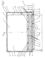
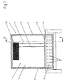
- Fig. 1 shows a first embodiment of an apparatus for Cooling a stored in a cooling chamber 1 of a vehicle 2 and / or transported cargo, not shown, in particular from foods such as meat, by means of a a cooling medium or coolant 3 and on the other hand from one Fan 4 acted upon heat exchanger 5, the coolant 3rd the cooling chamber air 6 contained in the cooling chamber cools.
- the storage container is advantageous 7 to form the heat exchanger 5 by the coolant 3 passes through sealed heat exchanger tubes 8, which have open ends 9 and 10 which are in contact with the air of the Interior of the cooling chamber 1 are connected.
- the battery used is usually a alternator-powered storage battery or a rechargeable battery.
- the storage container 7 is inside the Cooling chamber 1 of the vehicle 2 arranged, the heat exchanger tubes 8 with their open ends 9, 10 through each other opposing free walls 11, 12 of the storage container 7 through and form the open ends on the one hand Inlet openings 9 for the indoor air to be cooled 6 and on the other hand, outlet openings 10 for the cooled interior air 6.
- the storage container is 7 on the inner floor 13 of the cooling chamber 1 (see insulating walls 14) arranged and has two partitions Z for support, the 2 through openings Z 'for the coolant 3rd have.
- the outlet openings 10 of the Heat exchanger tubes 8 open into a ceiling 17 of the cooling chamber 1 leading air duct 18 in which the fan 4 is arranged and the under the ceiling 17 of the cooling chamber 1 an outlet 18 'for has the cooled indoor air 6.
- a removable Insert 19 arranged with cross supports 19 ', which is not Openings 20 shown for access to be cooled Internal air 6 to the inlet openings 9 of the heat exchanger tubes 8 has.
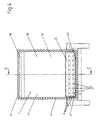
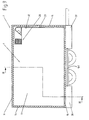
- the width b of the coolant tank 7 corresponds to FIG. 2 the width of the cooling chamber 1, its length L is on the one hand the depth T of the front wall 16 of the cooling chamber 1 arranged air duct 18 and on the other hand by the distance D of the storage container 7 from the rear wall 15 of the cooling chamber 1 limited.
- Openings 20 are provided in the insert base 19.
- the in the Storage tank 7 contained coolant to about minus 20 ° C. up to minus 30 ° C outside of the cooling chamber 1 on the vehicle 2 attached cooling unit 22 with plate heat exchanger 23 and Circulation pump (not shown) provided, a second Coolant in the form of a liquid containing, not Cooling tubes shown in a closed circuit, the coolant 3rd cool down the storage tank 7, which the cooling unit 22nd through a supply line 24 with circulation pump 25 from the Storage tank 7 supplied and after cooling through a derivative 26 from the cooling unit and the Storage tank is fed again.
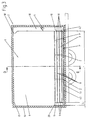
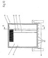
- FIG. 1 In the second embodiment shown in FIG Storage container 7 'due to its own lower bottom 42, the can slide more easily on rails 42 'from the cooling chamber 1 of the Removable vehicle 2, in an external, not shown, stationary cooling cell can be moved, cooled down there and at Need can be brought back into the cooling chamber 1.
- a separate refrigeration unit 22 (Fig. 1) on Vehicle 2 can be dispensed with.
- the function of the fan 4 is dependent on one adjustable thermostat controlled, which is not shown.
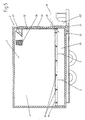
- FIG. 1 In the third embodiment shown in FIG Invention is a device for cooling a stored and / or in a cooling chamber 1 of a vehicle 2 transported cargo, not shown, especially from Food such as meat, on the one hand by one Coolant 29 and on the other hand from a fan 27 acted upon heat exchanger 28, the coolant 29 the in the cooling chamber or internal air 6 containing cooling chamber 1 cools.
- the heat exchanger 28 forms with its fan 27 an assembly arranged within the cooling chamber 1. Furthermore is at least one coolant 26 arranged on vehicle 2 containing, provided storage container 30, wherein in only one storage container 30 is shown in the present case is, although it is of course possible, as with the previous ones explained embodiments, multiple storage containers to be provided next to or on top of each other.
- the storage container 30 is connected to the heat exchanger 28 with the Fan 27 expediently in the area of the ceiling 17 of the cooling chamber 1 is arranged over with a battery-operated circulation pump 32 equipped connecting pipes 33, 34 (Fig. 7) connected. Furthermore, the fan 27 is battery operated and ensures Circulation of the inside air 6 of the cooling chamber 1 through the Heat exchanger 28 for cooling the same.
- the circulation pump 32 and / or the fan 27 in a manner not shown thermostatic switch.
- the storage container 30 is expedient on the inner floor 13 of the cooling room 1 is arranged.
- an insert base 19 is on arranged the storage container 30, which is not shown Cutouts for the passage of the connecting pipes 33, 34 from the storage container 30 to the heat exchanger 28.
- Coolant 29 Down to about minus 20 ° C to minus 30 ° C. an attached to the vehicle 2 outside the cooling chamber 1
- a fourth embodiment is shown, the of the third embodiment shown in FIG differs essentially in that the separate Cooling unit 36 is omitted. Instead it is Storage container 30 'after removal of the shelf 19 and after loosening screw connections, not shown, between him and the connecting pipes 33, 34 from the cooling chamber 1 of Removable vehicle 2, in an external, not shown, stationary cold room can be moved, cooled down and at Can be brought back into the cooling chamber 1 and again connected.
- FIG. 7 shows the section along the line F-F in FIG. 6.
- the two further exemplary embodiments according to FIGS. 8, 9 and 10 essentially correspond to the embodiments according to FIGS 5 and 6, with the difference that two through lines 41st connected coolant tank 38 and 39 under the vehicle floor 40 are arranged and which carry the coolant Connecting pipes 33, 34 through the vehicle floor 40 above to the heat exchanger arranged under the cooling chamber ceiling 17 28 are performed.
- FIG. 8 is a separate one in the embodiment of FIG Cooling unit 36 with its functions already described provided, while the embodiment of FIG. 9, thus the sixth embodiment, such a cooling unit 36 is not having.
- Coolant if it is flowable, from the or Storage container (s) in a separate, not shown Pump out the transport container in the transport container in a external, stationary, not shown, stationary freezer spend there to prepare or freeze and then bring it back in the shipping container and out the same again in the or the storage container in or on fill.
Landscapes
- Engineering & Computer Science (AREA)
- Chemical & Material Sciences (AREA)
- Combustion & Propulsion (AREA)
- Physics & Mathematics (AREA)
- Mechanical Engineering (AREA)
- Thermal Sciences (AREA)
- General Engineering & Computer Science (AREA)
- Devices That Are Associated With Refrigeration Equipment (AREA)
Applications Claiming Priority (2)
| Application Number | Priority Date | Filing Date | Title |
|---|---|---|---|
| DE10304545 | 2003-02-04 | ||
| DE10304545A DE10304545A1 (de) | 2003-02-04 | 2003-02-04 | Vorrichtung zum Kühlen einer in einer Kühlkammer eines Fahrzeugs gelagerten und/oder transportierten Ladung |
Publications (3)
| Publication Number | Publication Date |
|---|---|
| EP1445559A2 true EP1445559A2 (fr) | 2004-08-11 |
| EP1445559A3 EP1445559A3 (fr) | 2004-08-25 |
| EP1445559B1 EP1445559B1 (fr) | 2009-10-21 |
Family
ID=32603149
Family Applications (1)
| Application Number | Title | Priority Date | Filing Date |
|---|---|---|---|
| EP04002417A Expired - Lifetime EP1445559B1 (fr) | 2003-02-04 | 2004-02-04 | Dispositif frigorifique pour un chargement stocké et/ou transporté dans une chambre de refroidissement d'un véhicule |
Country Status (3)
| Country | Link |
|---|---|
| EP (1) | EP1445559B1 (fr) |
| AT (1) | ATE446489T1 (fr) |
| DE (3) | DE20321696U1 (fr) |
Cited By (3)
| Publication number | Priority date | Publication date | Assignee | Title |
|---|---|---|---|---|
| DE102013200746A1 (de) * | 2013-01-18 | 2014-07-24 | Blanco Professional Gmbh + Co Kg | Behälter und Verfahren zum Kühlen und/oder Kühlhalten eines Kühlguts |
| DE102013200744A1 (de) * | 2013-01-18 | 2014-07-24 | Blanco Professional Gmbh + Co Kg | Behälter zum Kühlen und/oder Kühlhalten eines Kühlguts sowie Befüllanlage und Verfahren zum Befüllen eines solchen Behälters |
| CN113977165A (zh) * | 2021-10-28 | 2022-01-28 | 重庆工业职业技术学院 | 一种汽车焊接设备用的冷却机构 |
Citations (1)
| Publication number | Priority date | Publication date | Assignee | Title |
|---|---|---|---|---|
| EP0399449A2 (fr) | 1989-05-23 | 1990-11-28 | SEA CONTAINERS ITALIA S.r.l. | Compartiment de transport réfrigéré pour denrées alimentaires et autres denrées périssables |
Family Cites Families (13)
| Publication number | Priority date | Publication date | Assignee | Title |
|---|---|---|---|---|
| US236339A (en) * | 1881-01-04 | Kennabd knott | ||
| US2153696A (en) * | 1934-02-03 | 1939-04-11 | Nash Kelvinator Corp | Air conditioning system |
| US2185022A (en) * | 1935-07-31 | 1939-12-26 | Gen Motors Corp | Refrigerating apparatus |
| US2180502A (en) * | 1936-12-12 | 1939-11-21 | Standard Railway Equipment Mfg | Refrigerator car floor rack |
| FR1327792A (fr) * | 1962-04-07 | 1963-05-24 | Perfectionnement aux équipements de conditionnement d'air pour véhicules ferroviaires et routiers | |
| US3228205A (en) * | 1963-09-12 | 1966-01-11 | Paul R Franklin | Palletized refrigeration unit |
| US4302944A (en) * | 1980-07-15 | 1981-12-01 | Westinghouse Electric Corp. | Thermal storage method and apparatus |
| GB2180049A (en) * | 1985-09-06 | 1987-03-18 | Trevor Colley Stuckey | Refrigeration system for a vehicle body |
| DE3807879C1 (en) * | 1988-03-10 | 1989-08-31 | Daimler-Benz Aktiengesellschaft, 7000 Stuttgart, De | Cooling device for cooling the interior of a motor vehicle |
| EP0412811B1 (fr) * | 1989-08-11 | 1994-07-06 | Sanyo Electric Co., Ltd. | Caisse frigorifique |
| US5090209A (en) * | 1990-10-01 | 1992-02-25 | General Cryogenics Incorporated | Enthalpy control for co2 refrigeration system |
| US5871041A (en) * | 1996-09-25 | 1999-02-16 | Mid-America Capital Resources, Inc. | Thermal energy storage and delivery apparatus and vehicular systems incorporating same |
| DE19735584C2 (de) * | 1997-08-16 | 1999-12-09 | Integral Energietechnik Gmbh | Doppelwandige Kühlzelle |
-
2003
- 2003-02-04 DE DE20321696U patent/DE20321696U1/de not_active Expired - Lifetime
- 2003-02-04 DE DE10304545A patent/DE10304545A1/de not_active Withdrawn
-
2004
- 2004-02-04 AT AT04002417T patent/ATE446489T1/de not_active IP Right Cessation
- 2004-02-04 DE DE502004010251T patent/DE502004010251D1/de not_active Expired - Lifetime
- 2004-02-04 EP EP04002417A patent/EP1445559B1/fr not_active Expired - Lifetime
Patent Citations (1)
| Publication number | Priority date | Publication date | Assignee | Title |
|---|---|---|---|---|
| EP0399449A2 (fr) | 1989-05-23 | 1990-11-28 | SEA CONTAINERS ITALIA S.r.l. | Compartiment de transport réfrigéré pour denrées alimentaires et autres denrées périssables |
Cited By (3)
| Publication number | Priority date | Publication date | Assignee | Title |
|---|---|---|---|---|
| DE102013200746A1 (de) * | 2013-01-18 | 2014-07-24 | Blanco Professional Gmbh + Co Kg | Behälter und Verfahren zum Kühlen und/oder Kühlhalten eines Kühlguts |
| DE102013200744A1 (de) * | 2013-01-18 | 2014-07-24 | Blanco Professional Gmbh + Co Kg | Behälter zum Kühlen und/oder Kühlhalten eines Kühlguts sowie Befüllanlage und Verfahren zum Befüllen eines solchen Behälters |
| CN113977165A (zh) * | 2021-10-28 | 2022-01-28 | 重庆工业职业技术学院 | 一种汽车焊接设备用的冷却机构 |
Also Published As
| Publication number | Publication date |
|---|---|
| DE20321696U1 (de) | 2009-06-04 |
| EP1445559B1 (fr) | 2009-10-21 |
| DE502004010251D1 (de) | 2009-12-03 |
| ATE446489T1 (de) | 2009-11-15 |
| DE10304545A1 (de) | 2004-08-19 |
| EP1445559A3 (fr) | 2004-08-25 |
Similar Documents
| Publication | Publication Date | Title |
|---|---|---|
| DE102009021442B4 (de) | Verteiltes Kühlsystem | |
| DE4307931B4 (de) | Verfahren zum Betrieb eines Mehrkammer-Transportkühlsystems | |
| DE2442407A1 (de) | Kuehlanlage fuer eine kuehlabteilung eines fahrzeuges | |
| EP2596978B1 (fr) | Véhicule thermique doté d'une cellule tempérée, isolée thermiquement | |
| EP3218215B1 (fr) | Système frigorifique | |
| DE2440769A1 (de) | Transportables kuehlaggregat fuer bewegliche kuehlbehaelter | |
| DE202007006732U1 (de) | Kühl- und/oder Gefriergerät | |
| DE102008028066A1 (de) | Verfahren zum Betreiben einer Standklimaanlage in einem Fahrzeug sowie Fahrzeug-Standklimaanlage | |
| WO2016202486A1 (fr) | Étagère réfrigérante | |
| DE202006009803U1 (de) | Verdampfungskühlanordnung für Fahrzeuge | |
| DE10223161A1 (de) | Hybridtemperaturregelsystem | |
| DE102010022993A1 (de) | Transportkältemaschine zum Kühlen des Innenraums | |
| DE68905936T2 (de) | Temperaturregelung für mehrere Abteile eines Kraftfahrzeuges. | |
| DE19907250A1 (de) | Kältemaschine | |
| DE102011105475A1 (de) | Wechselbehälter für ein Nutzfahrzeug | |
| DE202012103717U1 (de) | Thermischer Speicher für Kälteanlagen | |
| DE10304545A1 (de) | Vorrichtung zum Kühlen einer in einer Kühlkammer eines Fahrzeugs gelagerten und/oder transportierten Ladung | |
| EP0424700A1 (fr) | Automobile avec un moteur produisant de la chaleur perdue | |
| DE2047445A1 (de) | Warmeisoherter Behalter, insbe sondere sogenannter Container | |
| DE10306048B4 (de) | Klimatisierungssystem für ein Kraftfahrzeug | |
| DE102021132686A1 (de) | Kühlmitteltank, Kühlmittelkreislauf und Kraftfahrzeug | |
| DE102006061155A1 (de) | Kältegerät | |
| DE29816787U1 (de) | Verdampfungskühlanordnung für Frischdienst-Fahrzeuge mit kombinierter Fahr- und Standkühlung | |
| WO2005058623A1 (fr) | Dispositif de refroidissement de transport, ne presentant pas de dispositif production de froid dans le vehicule de transport | |
| DE102013200746A1 (de) | Behälter und Verfahren zum Kühlen und/oder Kühlhalten eines Kühlguts |
Legal Events
| Date | Code | Title | Description |
|---|---|---|---|
| PUAI | Public reference made under article 153(3) epc to a published international application that has entered the european phase |
Free format text: ORIGINAL CODE: 0009012 |
|
| PUAL | Search report despatched |
Free format text: ORIGINAL CODE: 0009013 |
|
| AK | Designated contracting states |
Kind code of ref document: A2 Designated state(s): AT BE BG CH CY CZ DE DK EE ES FI FR GB GR HU IE IT LI LU MC NL PT RO SE SI SK TR |
|
| AX | Request for extension of the european patent |
Extension state: AL LT LV MK |
|
| AK | Designated contracting states |
Kind code of ref document: A3 Designated state(s): AT BE BG CH CY CZ DE DK EE ES FI FR GB GR HU IE IT LI LU MC NL PT RO SE SI SK TR |
|
| AX | Request for extension of the european patent |
Extension state: AL LT LV MK |
|
| 17P | Request for examination filed |
Effective date: 20050221 |
|
| AKX | Designation fees paid |
Designated state(s): AT BE BG CH CY CZ DE DK EE ES FI FR GB GR HU IE IT LI LU MC NL PT RO SE SI SK TR |
|
| 17Q | First examination report despatched |
Effective date: 20070913 |
|
| GRAP | Despatch of communication of intention to grant a patent |
Free format text: ORIGINAL CODE: EPIDOSNIGR1 |
|
| GRAS | Grant fee paid |
Free format text: ORIGINAL CODE: EPIDOSNIGR3 |
|
| GRAA | (expected) grant |
Free format text: ORIGINAL CODE: 0009210 |
|
| AK | Designated contracting states |
Kind code of ref document: B1 Designated state(s): AT BE BG CH CY CZ DE DK EE ES FI FR GB GR HU IE IT LI LU MC NL PT RO SE SI SK TR |
|
| REG | Reference to a national code |
Ref country code: GB Ref legal event code: FG4D Free format text: NOT ENGLISH |
|
| REG | Reference to a national code |
Ref country code: CH Ref legal event code: EP |
|
| REG | Reference to a national code |
Ref country code: IE Ref legal event code: FG4D |
|
| REF | Corresponds to: |
Ref document number: 502004010251 Country of ref document: DE Date of ref document: 20091203 Kind code of ref document: P |
|
| NLV1 | Nl: lapsed or annulled due to failure to fulfill the requirements of art. 29p and 29m of the patents act | ||
| PG25 | Lapsed in a contracting state [announced via postgrant information from national office to epo] |
Ref country code: FI Free format text: LAPSE BECAUSE OF FAILURE TO SUBMIT A TRANSLATION OF THE DESCRIPTION OR TO PAY THE FEE WITHIN THE PRESCRIBED TIME-LIMIT Effective date: 20091021 Ref country code: PT Free format text: LAPSE BECAUSE OF FAILURE TO SUBMIT A TRANSLATION OF THE DESCRIPTION OR TO PAY THE FEE WITHIN THE PRESCRIBED TIME-LIMIT Effective date: 20100222 Ref country code: ES Free format text: LAPSE BECAUSE OF FAILURE TO SUBMIT A TRANSLATION OF THE DESCRIPTION OR TO PAY THE FEE WITHIN THE PRESCRIBED TIME-LIMIT Effective date: 20100201 Ref country code: SE Free format text: LAPSE BECAUSE OF FAILURE TO SUBMIT A TRANSLATION OF THE DESCRIPTION OR TO PAY THE FEE WITHIN THE PRESCRIBED TIME-LIMIT Effective date: 20091021 |
|
| REG | Reference to a national code |
Ref country code: IE Ref legal event code: FD4D |
|
| PG25 | Lapsed in a contracting state [announced via postgrant information from national office to epo] |
Ref country code: SI Free format text: LAPSE BECAUSE OF FAILURE TO SUBMIT A TRANSLATION OF THE DESCRIPTION OR TO PAY THE FEE WITHIN THE PRESCRIBED TIME-LIMIT Effective date: 20091021 |
|
| PG25 | Lapsed in a contracting state [announced via postgrant information from national office to epo] |
Ref country code: RO Free format text: LAPSE BECAUSE OF FAILURE TO SUBMIT A TRANSLATION OF THE DESCRIPTION OR TO PAY THE FEE WITHIN THE PRESCRIBED TIME-LIMIT Effective date: 20091021 Ref country code: IE Free format text: LAPSE BECAUSE OF FAILURE TO SUBMIT A TRANSLATION OF THE DESCRIPTION OR TO PAY THE FEE WITHIN THE PRESCRIBED TIME-LIMIT Effective date: 20091021 Ref country code: EE Free format text: LAPSE BECAUSE OF FAILURE TO SUBMIT A TRANSLATION OF THE DESCRIPTION OR TO PAY THE FEE WITHIN THE PRESCRIBED TIME-LIMIT Effective date: 20091021 Ref country code: DK Free format text: LAPSE BECAUSE OF FAILURE TO SUBMIT A TRANSLATION OF THE DESCRIPTION OR TO PAY THE FEE WITHIN THE PRESCRIBED TIME-LIMIT Effective date: 20091021 Ref country code: BG Free format text: LAPSE BECAUSE OF FAILURE TO SUBMIT A TRANSLATION OF THE DESCRIPTION OR TO PAY THE FEE WITHIN THE PRESCRIBED TIME-LIMIT Effective date: 20100121 |
|
| PLBE | No opposition filed within time limit |
Free format text: ORIGINAL CODE: 0009261 |
|
| STAA | Information on the status of an ep patent application or granted ep patent |
Free format text: STATUS: NO OPPOSITION FILED WITHIN TIME LIMIT |
|
| BERE | Be: lapsed |
Owner name: KALTETECHNIK KASPAR KARL Effective date: 20100228 |
|
| PG25 | Lapsed in a contracting state [announced via postgrant information from national office to epo] |
Ref country code: SK Free format text: LAPSE BECAUSE OF FAILURE TO SUBMIT A TRANSLATION OF THE DESCRIPTION OR TO PAY THE FEE WITHIN THE PRESCRIBED TIME-LIMIT Effective date: 20091021 Ref country code: CZ Free format text: LAPSE BECAUSE OF FAILURE TO SUBMIT A TRANSLATION OF THE DESCRIPTION OR TO PAY THE FEE WITHIN THE PRESCRIBED TIME-LIMIT Effective date: 20091021 |
|
| PGFP | Annual fee paid to national office [announced via postgrant information from national office to epo] |
Ref country code: DE Payment date: 20100429 Year of fee payment: 7 |
|
| 26N | No opposition filed |
Effective date: 20100722 |
|
| REG | Reference to a national code |
Ref country code: CH Ref legal event code: PL |
|
| GBPC | Gb: european patent ceased through non-payment of renewal fee |
Effective date: 20100204 |
|
| PG25 | Lapsed in a contracting state [announced via postgrant information from national office to epo] |
Ref country code: GR Free format text: LAPSE BECAUSE OF FAILURE TO SUBMIT A TRANSLATION OF THE DESCRIPTION OR TO PAY THE FEE WITHIN THE PRESCRIBED TIME-LIMIT Effective date: 20100122 Ref country code: CH Free format text: LAPSE BECAUSE OF NON-PAYMENT OF DUE FEES Effective date: 20100228 Ref country code: MC Free format text: LAPSE BECAUSE OF NON-PAYMENT OF DUE FEES Effective date: 20100301 Ref country code: LI Free format text: LAPSE BECAUSE OF NON-PAYMENT OF DUE FEES Effective date: 20100228 |
|
| REG | Reference to a national code |
Ref country code: FR Ref legal event code: ST Effective date: 20101029 |
|
| PG25 | Lapsed in a contracting state [announced via postgrant information from national office to epo] |
Ref country code: FR Free format text: LAPSE BECAUSE OF NON-PAYMENT OF DUE FEES Effective date: 20100301 |
|
| PG25 | Lapsed in a contracting state [announced via postgrant information from national office to epo] |
Ref country code: BE Free format text: LAPSE BECAUSE OF NON-PAYMENT OF DUE FEES Effective date: 20100228 |
|
| PG25 | Lapsed in a contracting state [announced via postgrant information from national office to epo] |
Ref country code: GB Free format text: LAPSE BECAUSE OF NON-PAYMENT OF DUE FEES Effective date: 20100204 Ref country code: IT Free format text: LAPSE BECAUSE OF FAILURE TO SUBMIT A TRANSLATION OF THE DESCRIPTION OR TO PAY THE FEE WITHIN THE PRESCRIBED TIME-LIMIT Effective date: 20091021 |
|
| PG25 | Lapsed in a contracting state [announced via postgrant information from national office to epo] |
Ref country code: AT Free format text: LAPSE BECAUSE OF NON-PAYMENT OF DUE FEES Effective date: 20100204 |
|
| REG | Reference to a national code |
Ref country code: DE Ref legal event code: R119 Ref document number: 502004010251 Country of ref document: DE Effective date: 20110901 |
|
| PG25 | Lapsed in a contracting state [announced via postgrant information from national office to epo] |
Ref country code: CY Free format text: LAPSE BECAUSE OF FAILURE TO SUBMIT A TRANSLATION OF THE DESCRIPTION OR TO PAY THE FEE WITHIN THE PRESCRIBED TIME-LIMIT Effective date: 20091021 |
|
| PG25 | Lapsed in a contracting state [announced via postgrant information from national office to epo] |
Ref country code: HU Free format text: LAPSE BECAUSE OF FAILURE TO SUBMIT A TRANSLATION OF THE DESCRIPTION OR TO PAY THE FEE WITHIN THE PRESCRIBED TIME-LIMIT Effective date: 20100422 Ref country code: NL Free format text: LAPSE BECAUSE OF FAILURE TO SUBMIT A TRANSLATION OF THE DESCRIPTION OR TO PAY THE FEE WITHIN THE PRESCRIBED TIME-LIMIT Effective date: 20091021 Ref country code: LU Free format text: LAPSE BECAUSE OF NON-PAYMENT OF DUE FEES Effective date: 20100204 |
|
| PG25 | Lapsed in a contracting state [announced via postgrant information from national office to epo] |
Ref country code: TR Free format text: LAPSE BECAUSE OF FAILURE TO SUBMIT A TRANSLATION OF THE DESCRIPTION OR TO PAY THE FEE WITHIN THE PRESCRIBED TIME-LIMIT Effective date: 20091021 |
|
| PG25 | Lapsed in a contracting state [announced via postgrant information from national office to epo] |
Ref country code: DE Free format text: LAPSE BECAUSE OF NON-PAYMENT OF DUE FEES Effective date: 20110901 |