EP1445568A2 - Element d'échange de chaleur - Google Patents
Element d'échange de chaleur Download PDFInfo
- Publication number
- EP1445568A2 EP1445568A2 EP04001513A EP04001513A EP1445568A2 EP 1445568 A2 EP1445568 A2 EP 1445568A2 EP 04001513 A EP04001513 A EP 04001513A EP 04001513 A EP04001513 A EP 04001513A EP 1445568 A2 EP1445568 A2 EP 1445568A2
- Authority
- EP
- European Patent Office
- Prior art keywords
- heat exchanger
- operating
- control
- exchanger assembly
- central
- Prior art date
- Legal status (The legal status is an assumption and is not a legal conclusion. Google has not performed a legal analysis and makes no representation as to the accuracy of the status listed.)
- Withdrawn
Links
- 239000002826 coolant Substances 0.000 claims description 67
- 239000000314 lubricant Substances 0.000 claims description 58
- 230000001050 lubricating effect Effects 0.000 claims description 4
- 230000002093 peripheral effect Effects 0.000 claims 1
- 230000008878 coupling Effects 0.000 description 8
- 238000010168 coupling process Methods 0.000 description 8
- 238000005859 coupling reaction Methods 0.000 description 8
- 238000009434 installation Methods 0.000 description 6
- 238000001816 cooling Methods 0.000 description 5
- 230000000712 assembly Effects 0.000 description 4
- 238000000429 assembly Methods 0.000 description 4
- 230000005540 biological transmission Effects 0.000 description 4
- 238000010276 construction Methods 0.000 description 4
- 230000006978 adaptation Effects 0.000 description 3
- 238000002485 combustion reaction Methods 0.000 description 2
- 239000012530 fluid Substances 0.000 description 2
- 230000010354 integration Effects 0.000 description 2
- 230000004048 modification Effects 0.000 description 2
- 238000012986 modification Methods 0.000 description 2
- 230000002146 bilateral effect Effects 0.000 description 1
- 230000007547 defect Effects 0.000 description 1
- 238000004519 manufacturing process Methods 0.000 description 1
- 239000000463 material Substances 0.000 description 1
- 238000000034 method Methods 0.000 description 1
- 238000005192 partition Methods 0.000 description 1
Images

Classifications
-
- F—MECHANICAL ENGINEERING; LIGHTING; HEATING; WEAPONS; BLASTING
- F16—ENGINEERING ELEMENTS AND UNITS; GENERAL MEASURES FOR PRODUCING AND MAINTAINING EFFECTIVE FUNCTIONING OF MACHINES OR INSTALLATIONS; THERMAL INSULATION IN GENERAL
- F16H—GEARING
- F16H57/00—General details of gearing
- F16H57/04—Features relating to lubrication or cooling or heating
- F16H57/0412—Cooling or heating; Control of temperature
- F16H57/0415—Air cooling or ventilation; Heat exchangers; Thermal insulations
-
- F—MECHANICAL ENGINEERING; LIGHTING; HEATING; WEAPONS; BLASTING
- F01—MACHINES OR ENGINES IN GENERAL; ENGINE PLANTS IN GENERAL; STEAM ENGINES
- F01P—COOLING OF MACHINES OR ENGINES IN GENERAL; COOLING OF INTERNAL-COMBUSTION ENGINES
- F01P3/00—Liquid cooling
- F01P3/18—Arrangements or mounting of liquid-to-air heat-exchangers
-
- F—MECHANICAL ENGINEERING; LIGHTING; HEATING; WEAPONS; BLASTING
- F28—HEAT EXCHANGE IN GENERAL
- F28D—HEAT-EXCHANGE APPARATUS, NOT PROVIDED FOR IN ANOTHER SUBCLASS, IN WHICH THE HEAT-EXCHANGE MEDIA DO NOT COME INTO DIRECT CONTACT
- F28D7/00—Heat-exchange apparatus having stationary tubular conduit assemblies for both heat-exchange media, the media being in contact with different sides of a conduit wall
- F28D7/0008—Heat-exchange apparatus having stationary tubular conduit assemblies for both heat-exchange media, the media being in contact with different sides of a conduit wall the conduits for one medium being in heat conductive contact with the conduits for the other medium
-
- F—MECHANICAL ENGINEERING; LIGHTING; HEATING; WEAPONS; BLASTING
- F28—HEAT EXCHANGE IN GENERAL
- F28D—HEAT-EXCHANGE APPARATUS, NOT PROVIDED FOR IN ANOTHER SUBCLASS, IN WHICH THE HEAT-EXCHANGE MEDIA DO NOT COME INTO DIRECT CONTACT
- F28D7/00—Heat-exchange apparatus having stationary tubular conduit assemblies for both heat-exchange media, the media being in contact with different sides of a conduit wall
- F28D7/0066—Multi-circuit heat-exchangers, e.g. integrating different heat exchange sections in the same unit or heat-exchangers for more than two fluids
- F28D7/0083—Multi-circuit heat-exchangers, e.g. integrating different heat exchange sections in the same unit or heat-exchangers for more than two fluids with units having particular arrangement relative to a supplementary heat exchange medium, e.g. with interleaved units or with adjacent units arranged in common flow of supplementary heat exchange medium
- F28D7/0091—Multi-circuit heat-exchangers, e.g. integrating different heat exchange sections in the same unit or heat-exchangers for more than two fluids with units having particular arrangement relative to a supplementary heat exchange medium, e.g. with interleaved units or with adjacent units arranged in common flow of supplementary heat exchange medium the supplementary medium flowing in series through the units
-
- F—MECHANICAL ENGINEERING; LIGHTING; HEATING; WEAPONS; BLASTING
- F28—HEAT EXCHANGE IN GENERAL
- F28F—DETAILS OF HEAT-EXCHANGE AND HEAT-TRANSFER APPARATUS, OF GENERAL APPLICATION
- F28F9/00—Casings; Header boxes; Auxiliary supports for elements; Auxiliary members within casings
-
- F—MECHANICAL ENGINEERING; LIGHTING; HEATING; WEAPONS; BLASTING
- F28—HEAT EXCHANGE IN GENERAL
- F28F—DETAILS OF HEAT-EXCHANGE AND HEAT-TRANSFER APPARATUS, OF GENERAL APPLICATION
- F28F9/00—Casings; Header boxes; Auxiliary supports for elements; Auxiliary members within casings
- F28F9/26—Arrangements for connecting different sections of heat-exchange elements, e.g. of radiators
-
- F—MECHANICAL ENGINEERING; LIGHTING; HEATING; WEAPONS; BLASTING
- F01—MACHINES OR ENGINES IN GENERAL; ENGINE PLANTS IN GENERAL; STEAM ENGINES
- F01P—COOLING OF MACHINES OR ENGINES IN GENERAL; COOLING OF INTERNAL-COMBUSTION ENGINES
- F01P2060/00—Cooling circuits using auxiliaries
- F01P2060/04—Lubricant cooler
-
- F—MECHANICAL ENGINEERING; LIGHTING; HEATING; WEAPONS; BLASTING
- F28—HEAT EXCHANGE IN GENERAL
- F28D—HEAT-EXCHANGE APPARATUS, NOT PROVIDED FOR IN ANOTHER SUBCLASS, IN WHICH THE HEAT-EXCHANGE MEDIA DO NOT COME INTO DIRECT CONTACT
- F28D21/00—Heat-exchange apparatus not covered by any of the groups F28D1/00 - F28D20/00
- F28D2021/0019—Other heat exchangers for particular applications; Heat exchange systems not otherwise provided for
- F28D2021/008—Other heat exchangers for particular applications; Heat exchange systems not otherwise provided for for vehicles
- F28D2021/0089—Oil coolers
-
- F—MECHANICAL ENGINEERING; LIGHTING; HEATING; WEAPONS; BLASTING
- F28—HEAT EXCHANGE IN GENERAL
- F28D—HEAT-EXCHANGE APPARATUS, NOT PROVIDED FOR IN ANOTHER SUBCLASS, IN WHICH THE HEAT-EXCHANGE MEDIA DO NOT COME INTO DIRECT CONTACT
- F28D7/00—Heat-exchange apparatus having stationary tubular conduit assemblies for both heat-exchange media, the media being in contact with different sides of a conduit wall
- F28D7/0066—Multi-circuit heat-exchangers, e.g. integrating different heat exchange sections in the same unit or heat-exchangers for more than two fluids
Definitions
- the invention relates to a heat exchanger assembly in a space-optimized manner Construction, in particular with the feature from the preamble of claim 1.
- Heat exchanger assemblies are known in a variety of designs. These are generally used to exchange heat between two Circuits and are used primarily for cooling equipment in Drive units used. Regarding possible designs and Basic designs can also be found, for example, on Buschmann, Koessler: “Handbuch der Automobiltechnik ", 1973. In general, these are two separate circuits are provided, a first circuit for the coolant and a second for the equipment, which is normally available as oil.
- the heat exchanger itself has at least one central feed channel and a central discharge channel for the operating medium and the coolant.
- the operating fluid flows through the heat exchanger as a cooling coil designated channels, which are surrounded by coolant or cooling medium.
- the Heat exchanger units are usually anywhere in the Drive system arranged so that connecting lines between the Drive components and the heat exchanger are to be created. Furthermore Designs are known in which the heat exchanger on the housing is flanged. In these versions, however, the design of Drive component with the space required for the heat exchanger unit considered.
- the heat exchanger units usually have one very simple geometric structure, which is easy integration allows. However, the one required in the radial as well as the axial direction Installation space for the heat exchanger are taken into account or the corresponding required connecting lines when arranging the Heat exchanger at a spatial distance from the drive component.
- the invention is therefore based on the object of a heat exchanger assembly to create in space-optimized design, which for arrangement in immediate proximity of the drive component is suitable and only makes minimal demands on the installation space to be made available.
- the heat exchanger assembly in a space-optimized design for arrangement or in a torque generating / torque converting or Transferring drive component comprises at least one Heat exchanger module, with at least one central supply line for operating and / or Control and / or lubricant and a central feed channel for the cooling medium, further at least one central discharge channel for the cooled operating and / or lubricating and / or control means and the cooling medium.
- the geometric design of the heat exchanger assembly takes place according to the invention in such a way that its outer contour is at least partially the input or output of a torque-generating or torque-transmitting drive component can enclose. This means that the heat exchanger assembly extends in the circumferential direction.
- This preferably encloses the input or output at an angle of> 90 degrees to ⁇ 360 degrees.
- the Heat exchanger assembly thus encloses an input or output, which also can be present as an input or output shaft, at least in the radial direction a partial area in the circumferential direction.
- the Heat exchanger units are preferably drives or drives, suitable for example in the form of small diameter shafts, because here the installation space available in the radial direction is the largest.
- versions that consist of only one Heat exchanger module exist or more comprises at least one central feed channel and at least one central discharge channel for the operating and / or to be cooled Control and / or lubricants as well as a central feed and one central discharge channel for the cooling medium.
- the feed and discharge channels are coupled with each other via connection channels. These are for the Operating and / or control and / or lubricants as operating and / or control and / or Lubricant guide channels and for the cooling medium as Coolant channel called.
- Channels in the heat exchanger module also consist of a variety of Possibilities, however, this depends on the specific choice of the type of Types of heat exchangers - for example, shell or plate construction.
- the terms line or channel are not to be understood here as meaning inevitably has to deal with corresponding constructive features that necessarily correspond to a line, but these are only intended to function play d.
- H the possibility of connection through channels in walls or but individual tubular guide elements can be given.
- a housing is provided on which the connections for the feed and Removal are provided and inside the connecting channels are arranged become.
- the outer contour is described by the shape of the housing, which for execution with at least partial wrapping in Circumferential direction is to be provided with a corresponding geometry.
- the housing can be U-shaped, the two legs arranged on both sides of the input or output shaft are or viewed in cross section in the form of a circular ring segment or circular.
- the one-piece design of the heat exchanger assembly offers the The advantage of a high degree of compactness.
- each includes Heat exchanger module a central supply and a central Discharge channel for the operating and / or lubricating and / or to be cooled Control means and the cooling medium.
- the heat exchanger modules are on both sides an input or output, preferably an input or output shaft torque-generating or torque-transmitting drive component arranged, preferably a mirror image.
- the coupling takes place via Corresponding connecting lines between the supply and discharge channels of the individual heat exchanger modules.
- the two can Heat exchanger modules both with regard to the channels carrying coolant also the operating and / or control and / or lubricant-carrying channels be connected to each other.
- Another option is to simply remove the heat exchanger modules operating and / or control and / or lubricant-carrying units to assemble that with each other via appropriate connecting lines are coupled, these operating and / or lubricating and / or Control unit-carrying units can be integrated in a housing, which also serves as a cooling medium guide channel.
- the housing provided with a central coolant supply and discharge channel. The contour the heat exchanger is largely in turn through the housing certainly.
- Versions with more than two modules are characterized in that the Modules are arranged one behind the other in the circumferential direction and together are coupled so that a module chain drives or drives a torque transmitting or torque generating device at least partially encloses in the circumferential direction.
- the individual Heat exchanger assembly or the individual module of the coolant and / or the medium to be cooled both single and multiple for example be flowed through twice.
- the feed and Processes can then, depending on the number of flows, on one side or on different sides.
- the attachment of the heat exchanger assembly can be form-fitting and / or done non-positively. A releasable connection is always preferred sought.
- the heat exchanger housing in particular the housing Heat exchanger assembly or individual modules can be from the heat exchanger itself, especially the media leading walls (plate heat exchangers) or the housing of the torque-transmitting or converting Units, such as the gearbox or sub-elements thereof, such as for example, drive or output cover.
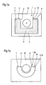
- FIG. 1 illustrates the basic principle of the in a highly schematic representation Design of a heat exchanger assembly 1 according to the invention in installation space optimized design.
- the heat exchanger assembly 1 is in the immediate vicinity spatial proximity to a drive component, in particular torque-generating or transmitting component, for example in Form of a drive machine or a gear unit, arranged in this integrated or attached to the housing 37.
- the outer contour 2 of the heat exchanger assembly 1 is designed such that it in the circumferential direction an input or output, in particular an input or Output shaft E or A of a drive component at least in the circumferential direction partially encloses.
- the heat exchanger assembly 1 can be different be carried out, however, comprises at least one heat exchanger module 3. This is designed in accordance with FIG.
- the heat exchanger module 3 comprises a housing 4, at least one arranged in the housing 4 Channel for guiding the medium to be cooled by the drive component, therefore below as an operating and / or control and / or lubricant guide channel Designated 5 and at least one in close proximity to this guided coolant channel 6, one during the flow Heat transfer from the operating and / or control and / or lubricant from the provided guide channel 5 to the coolant in the coolant channel 6 he follows.
- a plurality of alternately arranged are preferably each Operating and / or control and / or lubricant guide channels 5 and Coolant channels 6 are provided.
- the operating and / or tax and / or Lubricant guide channels 5 are preferably a common feed channel 7 and a common discharge channel 8 for operating and / or control and / or Lubricant assigned.
- Feed and discharge channels 7 and 8 this depends on Structure of the heat exchanger module, in particular the management of the individual Connection lines between these and the number of to be cooled, one different media.
- the heat exchanger assembly 1 between the internal combustion engine and gear assembly to arrange and both the engine cooling circuit the control and / or lubricant of the transmission via the Cool the heat exchanger assembly.
- This also applies to the coolant channels 6.
- These are at least a central feed channel 9 and a central discharge channel assigned for the cooling medium.
- the individual operating and / or tax and / or Lubricant guide channels 5 form the connecting channels between the central feed channel 7 and the central discharge channel 8, while the coolant channels 6 the connecting channels between the central one Form feed channel 9 and the central discharge channel 10.
- the outer contour 2 is designed such that the Housing 4 of the heat exchanger module 3 viewed in cross section in the installed position Is U-shaped.
- the central feed and discharge channels 7, 9 and 8 and 10 can be arranged at any point, for example central feed channels 7 and 9 arranged on different sides, as well the discharge channels 8 and 10, so that coolant and medium to be cooled flow through module 3 in opposite directions.
- the other one here The possibility shown includes the arrangement of the central feed channels 7 and 9 and discharge channels 8 and 10 each on a common side.
- the Housing 4 of the heat exchanger module 3 is formed by two legs 11 and 12 writable, which on both sides of the input and / or output shaft E or A are arranged and coupled to one another via a connecting element 13.
- FIG. 1 b illustrates an embodiment in which a single Heat exchanger module 3.1 b is provided, the housing 4.1 b an in essentially has a cross-sectional ring segment contour.
- This enables optimal adaptation to the input and / or output shaft E or A, the heat exchanger assembly 1.1 b due to the adaptation to the radius the input and / or output shaft E or A with a smaller size than in the figure 1 a can get by.
- FIG. 1a becomes.
- the Heat exchanger assembly 1 or 1.1b viewed in the circumferential direction in essentially over an angle of 270 ° around the input and / or output shaft E. or A.
- This solution offers the advantage that even when the Heat exchanger assembly 1 or the direct attachment to the housing a drive system unit that can have a high capacity.
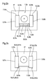
- FIGS. 2a to 2c illustrate two in a schematically simplified representation basic further possibilities of building one Heat exchanger assembly 1.2a, 1.2b and 1.2c.
- the heat exchanger assembly 1.2a consists of a plurality of heat exchanger modules 3.21a, 3.22a and 3.23a, these in a space-saving arrangement U-shaped around a drive or output can be arranged and via connecting channels to the Heat exchanger assembly 1.2a can be summarized as a structural unit can.
- the individual heat exchanger modules 3.21a, 3.22a and 3.23a can arranged in a common housing, not shown here accordingly, this also applies to the connection channels, or as in Figure 2a shown, each heat exchanger module has its own housing 4.21 a, 4.22a and 4.23a.
- Each housing has its own central one Feed channel 7.21 a, 7.22a and 7.23a and a central discharge channel 8.21 a, 8.22a and 8.23a for operating and / or control and / or lubricants.
- the individual feed channels 7.21 a, 7.22a and 7.23a are each with the central one Discharge channel 8.21 a, 8.22a or 8.23a via operating and / or control and / or Lubricant-carrying lines or channels 5.21a, 5.22a or 5.23a connected, illustrated here by broken lines. In analogy, this also applies for the coolant-carrying channels.
- Each heat exchanger module 3.21 a, 3.22a and 3.23a has at least one central feed channel 9.21a, 9.22a and 9.23a for the cooling medium and a central discharge duct 10.21a, 10.22a and 10.23a on.
- the individual feed channels 7.21a, 7.22a and 7.23a or the discharge channels 8.21 a, 8.22a and 8.23a and 9.21 a, 9.22a, 9.23a or 10.21a, 10.22a and 10.23a coupled so that the entire Heat exchanger assembly 1.2a only a central operating and / or Control and / or lubricant inlet 14.2a and an operating and / or control and / or Lubricant outlet 15.2a and a central coolant inlet 16.2a and has a coolant outlet 17.2a.
- the central operating and / or Control and / or lubricant inlet 14.2a is from the central feed channel 7.21a of the first module 3.21a formed during the central operating and / or Control and / or lubricant outlet 15.2a from discharge channel 8.23a of the third Module 3.23a is formed.
- the central coolant inlet 16.2a Heat exchanger assembly 1.2a is from the central feed channel 9.21 a of first heat exchanger module 3.21a and the coolant outlet 17.2a from Discharge channel 10.23a of the third heat exchanger module 3.23a is formed. A other assignment to any module is also conceivable.
- the coupling of the individual modules 3.21 a, 3.22a, 3.23a takes place via connecting lines, in The case shown is the central one belonging to the heat exchanger module 3.21a Discharge channel 8.21a for operating and / or control and / or lubricants with the central feed channel 7.22a of the second heat exchanger module via the Connection line 18.2a for operating and / or control and / or lubricants coupled.
- the coolant is transferred via the connecting line 19.2a, which the discharge channel 10.21a with the feed channel 9.22a of the second Heat exchanger modules 3.22a connects. In analogy, this also applies to the Coupling between the second heat exchanger module 3.22a and the third Heat exchanger module 3.23a.
- These are through the connecting lines 20.2a for the operating and / or control and / or lubricant and Connection line 21.2a realized for the cooling medium.
- FIG. 2a is a Particularly easy to implement, which is an optimal Enclosing a torque-transmitting element with little Diameter enables and thus possibly existing empty spaces in the Can optimally utilize the drive train, whereby here standardized designs of heat exchangers can be used as individual Heat exchanger modules combined to form a heat exchanger assembly 1.2a can be.
- the assembly is done in a simple manner. There is also no need to consider dimensions in horizontal and vertical Direction of the drive train can be taken with this version standardized heat exchanger modules are used.
- the in Figure 2a shown execution is one possibility. An in is also conceivable Arrangement of several small circumferential direction Heat exchanger modules, but here the connection effort is greater.
- the outer contour 2.2a of the heat exchanger assembly 1.2a very strongly to the The outer circumference of the input and / or output shaft E or A can be adjusted and thus a minimal distance between the torque in each area transmitting element, in particular the outer circumference of the attachment and / or Output shaft E or A and in the radial direction from this inner dimensions of the heat exchanger assembly 1.2a.
- FIG. 2b illustrates a further embodiment of a Heat exchanger assembly 1.2b, which is an element of a radial Torque transmitting or converting drive component in the form of a Input and / or output shaft E or A at least partially in the circumferential direction encloses.
- This version is due to the bilateral arrangement of Heat exchanger modules 3.21 b and 3.22b in addition to an input and / or output shaft Characterized E or A, these via corresponding connection channels are coupled together.
- the coupling of the first Heat exchanger module 3.21 b takes place with the second heat exchanger module 3.22b via a connecting line 22.2b for operating and / or control and / or Lubricant and a connecting line 23.2b for the coolant.
- Figure 2c discloses an embodiment in which the Heat exchanger assembly 1.2c also from two heat exchanger modules 3.21 c and 3.22c, both with respect to the coolant channels, however form completed modules.
- every heat exchanger module 3.21c and 3.22c via a separate central feed channel 9.21c and 9.22c as well has its own discharge channel 10.21c and 10.22c, the individual
- heat exchanger modules 3.21c and 3.22c are not coupled to one another are and only a coupling with regard to the management of the operating and / or Control and / or lubricant takes place.
- the central Drain channel 8.21c and the central feed channel 7.22c of the second Coupled heat exchanger module 3.22c are not coupled to one another are and only a coupling with regard to the management of the operating and / or Control and / or lubricant takes place.
- the central Drain channel 8.21c and the central feed channel 7.22c of the second Coupled heat exchanger module 3.22c are not coupled to one another are and only a coupling with regard to the
- the central feed channel 7.21c forms the central operating and / or control and / or Lubricant inlet 24.2c, while the central discharge channel 8.22c at the same time the central operating and / or control and / or lubricant outlet 25.2c forms.
- the heat exchanger assembly 2.2c further comprises two central ones Coolant inlets, which are formed by the supply channels 9.21 c and 9.22c and here designated with 26.2c and 27.2c and further two central ones Coolant leaks, which are designated here with 28.2c and 29.2c.
- the central one Coolant outlets 28.2c and 29.2c are thereby from the individual coolant discharge channels 10.21 c and 10.22c of the individual heat exchanger modules 3.21 c and 3.22c formed.
- only heat exchange takes place considered in individual sub-areas in the circumferential direction by a connection and / or Output shaft E or A.
- This version is also relative to standard modules easy to manufacture.
- the individual Heat exchanger modules can be integrated in a common housing, which with regard to its outer contour is designed such that an input or output of a torque transmitting or converting element in Circumferential direction is at least partially enclosed.
- the other possibility consists of each heat exchanger module with its own housing to equip, the individual modules then having corresponding outside the housing guided connecting lines are coupled together.
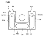
- FIG. 2d discloses an embodiment of a heat exchanger assembly 1.2d, comprising a housing 38 which, viewed in cross section, is U-shaped is designed and with the two legs 40 and 41 forming areas an input or output of a torque transmitting or converting Component encloses.
- a housing 38 which, viewed in cross section, is U-shaped is designed and with the two legs 40 and 41 forming areas an input or output of a torque transmitting or converting Component encloses.
- the housing are operational and / or control and / or lubricant-carrying units, which the individual Heat exchanger modules 3.21d, 3.22d and 3.23d are assigned.
- Each of these Modules 3.21d, 3.22d and 3.23d comprise a central feed channel 7.21d to 7.23d for operating and / or control and / or lubricants as well as a central one Drainage channel 8.21d to 8.23d.
- the individual modules 3.21d, 3.22d and 3.23d are each in the area of their central feed and discharge channels 8.21d, 7.22d and 8.22d and 7.23d connected to each other.
- the central feed channel 7.21d of the first Module 3.21d simultaneously forms the central feed channel 7.2d of the Heat exchanger assembly 1.2d.
- the central discharge channel 8.23d of the third Modules 3.23d form the central discharge channel 8.2d of the Heat exchanger assembly 1.2d.
- the coolant-carrying part assigned, which of the housing 37, in particular the housing wall 38 is formed.
- the housing has a central feed channel 9.2d for the Cooling medium and a central discharge channel 10.2d.
- the cooling medium flows around all three modules 3.21d, 3.22d and 3.23d. Other designs are also conceivable.
- FIGS. 1a, 1b and 2a to 2d are advantageous embodiments of the solution according to the invention, which however are not a final list. Other options are conceivable.
- the figures only serve to illustrate possible basic structures.
- the versions shown relate to versions with only one Cooling medium. However, it is also conceivable that two different cooling media are used, the operating and / or control and / or lubricant flow around both sides. However, it is also conceivable for the connecting channels between the individual central supply and discharge channels for coolant to design that within the heat exchanger module a division of the Coolant takes place in two partial flows, which in turn also the operating and / or Flow around control and / or lubricants on both sides. Furthermore can with such a modification for the coolant channels Modification with regard to the management of different operating and / or Control and / or lubricants are made. Furthermore, the The heat exchanger module can be designed as a plate or shell. In this regard, any conventional heat exchanger assembly be used.
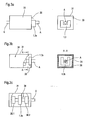
- FIGS. 3a, 3b and 3c illustrate specific arrangement options for a Heat exchanger assembly 1 designed according to the invention.
- FIG. 3a illustrates an embodiment with one on one end face 30 Drive system unit 31, for example in the form of a drive machine or a gear unit, flanged heat exchanger unit 1.3a.
- the heat exchanger assembly 1.3a extends in the radial direction viewed at least partially in the circumferential direction around the input or output shaft A for gear units or E in the form of a drive shaft Drive machines, for example in the form of an electric motor.
- the attachment can in a conventional manner on the housing 32 of the Drive system units take place, for example non-positively and / or positively, these couplings can be released.
- FIG. 3b illustrates an embodiment with an arrangement according to the invention designed heat exchanger assembly 1.3b in the housing 31 one Drive system unit in the form of a gear unit 34.
- the Flanged heat exchanger assembly 1.3b on the inside of a housing wall 38 and encloses the transmission output shaft A in viewed in the direction of force flow Circumferential direction at least partially.
- FIG. 3c discloses another possible one Design option in which the integration of an inventive designed heat exchanger assembly 1.3c in a drive system unit 35 in Form of a gear unit takes place, the arrangement by between power-transmitting elements is provided, simplified here schematically illustrates in the form of speed / torque converting units 36.1 until 36.2. This is due to a coupling between in the radial direction the individual speed / torque converting units available Space optimally used in the radial direction.
- the connection of the Heat exchanger assembly 1.3c can, for example, on an intermediate wall 39 respectively.
Landscapes
- Engineering & Computer Science (AREA)
- General Engineering & Computer Science (AREA)
- Mechanical Engineering (AREA)
- Physics & Mathematics (AREA)
- Thermal Sciences (AREA)
- Chemical & Material Sciences (AREA)
- Combustion & Propulsion (AREA)
- Heat-Exchange Devices With Radiators And Conduit Assemblies (AREA)
- Cooling Or The Like Of Semiconductors Or Solid State Devices (AREA)
Applications Claiming Priority (2)
| Application Number | Priority Date | Filing Date | Title |
|---|---|---|---|
| DE2003103416 DE10303416B4 (de) | 2003-01-29 | 2003-01-29 | Wärmetauscherbaueinheit |
| DE10303416 | 2003-01-29 |
Publications (2)
| Publication Number | Publication Date |
|---|---|
| EP1445568A2 true EP1445568A2 (fr) | 2004-08-11 |
| EP1445568A3 EP1445568A3 (fr) | 2005-11-16 |
Family
ID=32603016
Family Applications (1)
| Application Number | Title | Priority Date | Filing Date |
|---|---|---|---|
| EP04001513A Withdrawn EP1445568A3 (fr) | 2003-01-29 | 2004-01-24 | Element d'échange de chaleur |
Country Status (2)
| Country | Link |
|---|---|
| EP (1) | EP1445568A3 (fr) |
| DE (1) | DE10303416B4 (fr) |
Families Citing this family (4)
| Publication number | Priority date | Publication date | Assignee | Title |
|---|---|---|---|---|
| DE102008057510A1 (de) | 2008-11-15 | 2010-05-20 | Dr.Ing.H.C.F.Porsche Aktiengesellschaft | Getriebe für ein Kraftfahrzeug |
| DE102009005896A1 (de) * | 2009-01-23 | 2010-07-29 | Audi Ag | Vorrichtung zum Konditionieren von in einem Antriebsaggregat befindlichem Schmieröl |
| DE102010010816B4 (de) * | 2010-03-09 | 2025-02-27 | Sew-Eurodrive Gmbh & Co Kg | Getriebe |
| DE102012111963B4 (de) * | 2012-12-07 | 2021-07-08 | Dr. Ing. H.C. F. Porsche Aktiengesellschaft | Achsgetriebeeinheit für ein Kraftfahrzeug |
Citations (1)
| Publication number | Priority date | Publication date | Assignee | Title |
|---|---|---|---|---|
| EP1253392A1 (fr) * | 2001-04-25 | 2002-10-30 | Modine Manufacturing Company | Système de refroidissement |
Family Cites Families (9)
| Publication number | Priority date | Publication date | Assignee | Title |
|---|---|---|---|---|
| BR8008910A (pt) * | 1979-12-03 | 1981-10-20 | Caterpillar Tractor Co | Nucleo de permutador de calor com tampas extremas |
| US4324375A (en) * | 1979-12-26 | 1982-04-13 | General Dynamics Corporation | Heat sink/fluid-to-fluid mechanical coupling of spacecraft coolant systems |
| US4373577A (en) * | 1980-07-21 | 1983-02-15 | International Harvester Co. | Heat exchanger assembly |
| JPH0359392A (ja) * | 1989-07-26 | 1991-03-14 | Matsushita Electric Ind Co Ltd | 熱交換器 |
| DE19625357B4 (de) * | 1996-06-25 | 2009-06-18 | Zf Friedrichshafen Ag | Getriebe-integrierter Wärmetauscher |
| DE19641451A1 (de) * | 1996-10-08 | 1997-03-20 | Voith Turbo Kg | Antriebseinheit, insbesondere für ein Kraftfahrzeug |
| DE19641557A1 (de) * | 1996-10-09 | 1997-06-26 | Voith Turbo Kg | Antriebseinheit mit einem Motor, einem Getriebe und einem Kühlmittelkreislauf |
| DE10058110B4 (de) * | 2000-11-23 | 2010-06-17 | Zf Friedrichshafen Ag | Automatgetriebe |
| JP2002243381A (ja) * | 2001-02-16 | 2002-08-28 | Daikin Ind Ltd | 空気熱交換器およびその製造方法 |
-
2003
- 2003-01-29 DE DE2003103416 patent/DE10303416B4/de not_active Expired - Lifetime
-
2004
- 2004-01-24 EP EP04001513A patent/EP1445568A3/fr not_active Withdrawn
Patent Citations (1)
| Publication number | Priority date | Publication date | Assignee | Title |
|---|---|---|---|---|
| EP1253392A1 (fr) * | 2001-04-25 | 2002-10-30 | Modine Manufacturing Company | Système de refroidissement |
Also Published As
| Publication number | Publication date |
|---|---|
| DE10303416A1 (de) | 2004-08-12 |
| DE10303416B4 (de) | 2006-02-16 |
| EP1445568A3 (fr) | 2005-11-16 |
Similar Documents
| Publication | Publication Date | Title |
|---|---|---|
| EP4077991B1 (fr) | Dispositif pour manipuler un fluide dans un véhicule à entraînement électrique au moins partiel | |
| DE102012022452B4 (de) | Elektrische Maschine und Kraftfahrzeug-Antriebsstrang | |
| DE3874730T2 (de) | Waermeaustauschanordnung zur kuehlung eine maschine. | |
| DE3403429C2 (fr) | ||
| DE112012004145T5 (de) | Fahrzeugantriebsvorrichtung | |
| DE102016222331A1 (de) | Stator für eine elektrische Maschine, insbesondere eines Kraftfahrzeugs, sowie elektrische Maschine, insbesondere für ein Kraftfahrzeug | |
| EP3371540A1 (fr) | Module échangeur thermique | |
| DE202021102042U1 (de) | Zwei Wärmetauscher mit integriertem Umleitventil | |
| DE102022202758A1 (de) | Antriebsvorrichtung und Fahrzeug | |
| DE102022128451A1 (de) | Antriebsvorrichtung | |
| DE69411656T2 (de) | Lamellenwärmetauscher, insbesondere als Ölkühler benutzt | |
| DE102019211523A1 (de) | Kühlfluidführungsanordnung zum Kühlen eines Rotors einer elektrischen Maschine | |
| DE102014112223A1 (de) | Kühleinrichtung | |
| DE10303416B4 (de) | Wärmetauscherbaueinheit | |
| DE102015205141A1 (de) | Fluidgekühlte Antriebseinheit für ein Kraftfahrzeug | |
| DE102020211432A1 (de) | Elektrische Antriebseinheit und ein Fahrzeug mit einer entsprechenden elektrischen Antriebseinheit | |
| EP0504565B1 (fr) | Train épicycloidal à plusieurs étages | |
| EP1608895B1 (fr) | Unite echangeur de chaleur-transmission | |
| DE102021214080A1 (de) | Antriebsvorrichtung | |
| DE69505173T2 (de) | Verbindungsanordnung für Druckmediumkanäle in einem Dieselmotor | |
| DE102020115905A1 (de) | Stator für eine elektrische Maschine zum Antrieb eines Kraftfahrzeugs | |
| EP3273018B1 (fr) | Barre mécanique d'un entraînement de véhicule | |
| DE102017207807A1 (de) | Wärmetauscher und diesen einschließender Betriebsmittelkreislauf | |
| DE102015219718A1 (de) | Kraftfahrzeuggetriebe | |
| DE102020003883A1 (de) | Statormantelkühlung |
Legal Events
| Date | Code | Title | Description |
|---|---|---|---|
| PUAI | Public reference made under article 153(3) epc to a published international application that has entered the european phase |
Free format text: ORIGINAL CODE: 0009012 |
|
| AK | Designated contracting states |
Kind code of ref document: A2 Designated state(s): AT BE BG CH CY CZ DE DK EE ES FI FR GB GR HU IE IT LI LU MC NL PT RO SE SI SK TR |
|
| AX | Request for extension of the european patent |
Extension state: AL LT LV MK |
|
| PUAL | Search report despatched |
Free format text: ORIGINAL CODE: 0009013 |
|
| AK | Designated contracting states |
Kind code of ref document: A3 Designated state(s): AT BE BG CH CY CZ DE DK EE ES FI FR GB GR HU IE IT LI LU MC NL PT RO SE SI SK TR |
|
| AX | Request for extension of the european patent |
Extension state: AL LT LV MK |
|
| RIC1 | Information provided on ipc code assigned before grant |
Ipc: 7F 01P 3/18 B Ipc: 7F 28F 9/26 B Ipc: 7F 28D 7/00 A |
|
| 17P | Request for examination filed |
Effective date: 20051118 |
|
| AKX | Designation fees paid |
Designated state(s): AT BE BG CH CY CZ DE DK EE ES FI FR GB GR HU IE IT LI LU MC NL PT RO SE SI SK TR |
|
| 17Q | First examination report despatched |
Effective date: 20100812 |
|
| STAA | Information on the status of an ep patent application or granted ep patent |
Free format text: STATUS: THE APPLICATION HAS BEEN WITHDRAWN |
|
| 18W | Application withdrawn |
Effective date: 20101122 |