EP1445570B1 - Tube d'échangeur de chaleur comprenant un insert ondulé et son procédé de fabrication - Google Patents
Tube d'échangeur de chaleur comprenant un insert ondulé et son procédé de fabrication Download PDFInfo
- Publication number
- EP1445570B1 EP1445570B1 EP04000378.2A EP04000378A EP1445570B1 EP 1445570 B1 EP1445570 B1 EP 1445570B1 EP 04000378 A EP04000378 A EP 04000378A EP 1445570 B1 EP1445570 B1 EP 1445570B1
- Authority
- EP
- European Patent Office
- Prior art keywords
- wave
- heat exchanger
- exchanger tube
- section
- insert
- Prior art date
- Legal status (The legal status is an assumption and is not a legal conclusion. Google has not performed a legal analysis and makes no representation as to the accuracy of the status listed.)
- Revoked
Links
- 238000004519 manufacturing process Methods 0.000 title claims description 10
- 238000000034 method Methods 0.000 claims description 5
- 229910052751 metal Inorganic materials 0.000 claims description 3
- 239000002184 metal Substances 0.000 claims description 3
- 238000007493 shaping process Methods 0.000 claims 2
- 238000001816 cooling Methods 0.000 description 5
- 239000000110 cooling liquid Substances 0.000 description 4
- 239000000463 material Substances 0.000 description 4
- 229910052782 aluminium Inorganic materials 0.000 description 2
- XAGFODPZIPBFFR-UHFFFAOYSA-N aluminium Chemical compound [Al] XAGFODPZIPBFFR-UHFFFAOYSA-N 0.000 description 2
- 230000015572 biosynthetic process Effects 0.000 description 2
- 238000002360 preparation method Methods 0.000 description 2
- 238000004080 punching Methods 0.000 description 2
- 230000002349 favourable effect Effects 0.000 description 1
- 239000002699 waste material Substances 0.000 description 1
Images

Classifications
-
- F—MECHANICAL ENGINEERING; LIGHTING; HEATING; WEAPONS; BLASTING
- F28—HEAT EXCHANGE IN GENERAL
- F28F—DETAILS OF HEAT-EXCHANGE AND HEAT-TRANSFER APPARATUS, OF GENERAL APPLICATION
- F28F3/00—Plate-like or laminated elements; Assemblies of plate-like or laminated elements
- F28F3/02—Elements or assemblies thereof with means for increasing heat-transfer area, e.g. with fins, with recesses, with corrugations
- F28F3/025—Elements or assemblies thereof with means for increasing heat-transfer area, e.g. with fins, with recesses, with corrugations the means being corrugated, plate-like elements
-
- B—PERFORMING OPERATIONS; TRANSPORTING
- B21—MECHANICAL METAL-WORKING WITHOUT ESSENTIALLY REMOVING MATERIAL; PUNCHING METAL
- B21D—WORKING OR PROCESSING OF SHEET METAL OR METAL TUBES, RODS OR PROFILES WITHOUT ESSENTIALLY REMOVING MATERIAL; PUNCHING METAL
- B21D13/00—Corrugating sheet metal, rods or profiles; Bending sheet metal, rods or profiles into wave form
- B21D13/02—Corrugating sheet metal, rods or profiles; Bending sheet metal, rods or profiles into wave form by pressing
-
- B—PERFORMING OPERATIONS; TRANSPORTING
- B21—MECHANICAL METAL-WORKING WITHOUT ESSENTIALLY REMOVING MATERIAL; PUNCHING METAL
- B21D—WORKING OR PROCESSING OF SHEET METAL OR METAL TUBES, RODS OR PROFILES WITHOUT ESSENTIALLY REMOVING MATERIAL; PUNCHING METAL
- B21D53/00—Making other particular articles
- B21D53/02—Making other particular articles heat exchangers or parts thereof, e.g. radiators, condensers fins, headers
- B21D53/04—Making other particular articles heat exchangers or parts thereof, e.g. radiators, condensers fins, headers of sheet metal
-
- F—MECHANICAL ENGINEERING; LIGHTING; HEATING; WEAPONS; BLASTING
- F28—HEAT EXCHANGE IN GENERAL
- F28D—HEAT-EXCHANGE APPARATUS, NOT PROVIDED FOR IN ANOTHER SUBCLASS, IN WHICH THE HEAT-EXCHANGE MEDIA DO NOT COME INTO DIRECT CONTACT
- F28D9/00—Heat-exchange apparatus having stationary plate-like or laminated conduit assemblies for both heat-exchange media, the media being in contact with different sides of a conduit wall
- F28D9/0031—Heat-exchange apparatus having stationary plate-like or laminated conduit assemblies for both heat-exchange media, the media being in contact with different sides of a conduit wall the conduits for one heat-exchange medium being formed by paired plates touching each other
- F28D9/0043—Heat-exchange apparatus having stationary plate-like or laminated conduit assemblies for both heat-exchange media, the media being in contact with different sides of a conduit wall the conduits for one heat-exchange medium being formed by paired plates touching each other the plates having openings therein for circulation of at least one heat-exchange medium from one conduit to another
- F28D9/005—Heat-exchange apparatus having stationary plate-like or laminated conduit assemblies for both heat-exchange media, the media being in contact with different sides of a conduit wall the conduits for one heat-exchange medium being formed by paired plates touching each other the plates having openings therein for circulation of at least one heat-exchange medium from one conduit to another the plates having openings therein for both heat-exchange media
-
- F—MECHANICAL ENGINEERING; LIGHTING; HEATING; WEAPONS; BLASTING
- F28—HEAT EXCHANGE IN GENERAL
- F28F—DETAILS OF HEAT-EXCHANGE AND HEAT-TRANSFER APPARATUS, OF GENERAL APPLICATION
- F28F2215/00—Fins
- F28F2215/04—Assemblies of fins having different features, e.g. with different fin densities
-
- Y—GENERAL TAGGING OF NEW TECHNOLOGICAL DEVELOPMENTS; GENERAL TAGGING OF CROSS-SECTIONAL TECHNOLOGIES SPANNING OVER SEVERAL SECTIONS OF THE IPC; TECHNICAL SUBJECTS COVERED BY FORMER USPC CROSS-REFERENCE ART COLLECTIONS [XRACs] AND DIGESTS
- Y10—TECHNICAL SUBJECTS COVERED BY FORMER USPC
- Y10S—TECHNICAL SUBJECTS COVERED BY FORMER USPC CROSS-REFERENCE ART COLLECTIONS [XRACs] AND DIGESTS
- Y10S165/00—Heat exchange
- Y10S165/916—Oil cooler
Definitions
- the invention relates to a heat exchanger tube with a corrugated t having the features of the preamble of claims 1 and 3 respectively. Moreover, the invention relates to a manufacturing method for corrugated use.
- the object of the invention is to provide a corrugated insert which can be produced with the least possible effort and with which an optimized ratio of the cooling capacity to the pressure loss in a heat exchanger is possible.
- the troughs have about twice the length of the wave crests.
- a larger wavelength of the insert leads to a lower pressure loss.
- the terms "wave troughs” and “wave crests” are interchangeable because they depend on the viewer's point of view.
- the one-piece insert is formed of different wavelengths. For example, at the beginning of the insert there may be a portion of lesser wavelength followed by a middle portion of longer wavelength, which in turn merges into an end portion of lesser wavelength. This order can also be changed as needed.
- Each section preferably consists of several waves of equal length.
- the feed rate or feed of the strip material be changed accordingly to provide portions of greater or lesser wavelength (pitch).
- a smaller wavelength is realized by a lower feed rate or a smaller feed and a larger wavelength consequently by a higher feed rate or a larger feed. Accordingly, no or at least only minor changes to the punching tool or other expenditures are required for the production of such inserts.
- Only the speed of the tape feed or alternatively the continuous stroke speed of the press or the size of the feed must be pre-programmed accordingly to obtain the desired formation of the insert. Larger or smaller feeds can be realized by changing the angular positions of the eccentric shaft of the press, between which the feed can take place.
- the insert is designed in such a way that the optimal or desired ratio of the cooling capacity to the pressure loss is achieved for the respective application.
- the methods according to the invention consist, in other words, of exploiting the known technical possibilities of the forming machine specifically for the production of inserts for heat exchanger tubes in order to form them with shorter and / or longer wavelengths so that they fulfill certain requirements with regard to the heat exchange can.
- an insert can be made, for example, has a portion of any length, in which no waves are present, or only a single long drawn wave, which is thus flat.
- Such a section is preceded by at least one section of waves, and at least one section of waves adjoins the non-waved section.
- Such configurations of corrugated inserts are desired in some cases because they may, for example, avoid the use of multiple individual inserts.
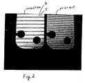
- FIGS. 1 and 2 show photographic images of a known insert and an insert according to the invention.
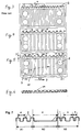
- FIG. 3 is a schematic representation of a known use and the FIGS. 4 and 5 are inserts, but according to the present invention.
- the Fig. 6 shows a non-inventive view of the end of a flat tube and the Fig. 7 shows an insert which has been produced by a further method according to the invention.
- the heat exchanger tube can be designed as desired.
- the heat exchanger tube of the embodiment is on the EP 742 418 B1 and there especially on the Fig. 7 directed.
- the heat exchanger tube for example, consists of two tube shells which are nested, being soldered tight at its edge, but their heat exchange surfaces are spaced and limit the space in which the insert is located.
- the heat exchanger tube has at least one inlet opening 7 and an outlet opening 8, which in the Fig. 5 are designated.
- the oil flows through the heat exchanger tube and is in heat exchange with the flowed through by the cooling liquid upper and lower heat exchanger tube, as is known from the above Fig. 7 the EP's clearly visible.
- inventions 1 and 2 Illustrated with "invention" images provided that the wave troughs 2 have a greater length than the wave crests 2.
- the wavelength 4 often referred to as pitch was increased compared to the prior art.
- the length of the wave troughs 2 is about twice as long as the length of the wave crests 1. It can be understood that thereby the pressure loss can be reduced, because the oil and / or the cooling liquid on the way from the inlet opening 7 to the outlet opening 8 less waves or breakthroughs 5 has to overcome than in a use according to the prior art.
- the insert is an insert made on a press in a punching tool.
- the preparation is made of an "endless" strip material, preferably of aluminum, which is very well known in the prior art and therefore not shown in a figure.
- the metal strip is down from the so-called coil with a certain low but constant over the entire use feed rate and transported through the punch to a use according to Fig. 3 or to produce according to the prior art.
- the feed rate is in the production of the in Fig. 4 shown use also constant but higher than in the prior art according to Fig. 3 ,
- this insert has an approximately twice the wavelength 4 than the one after Fig. 3 ,
- the feed rate is changed at intervals. First, the initial section A1 is produced at a constant but reduced speed. Then, at a constant but increased feed speed or with increased feed, the center portion A2 is made to immediately reduce the speed or the feed back to the value of the initial portion A1 to produce the end portion A3 .
- the speed amounts or feeds can be determined by tests. In general, a higher speed or a larger feed leads to longer wavelengths and vice versa, reduced speed to smaller wavelengths.
- the continuous stroke speed of the press is varied.
- the section A1 with a Treasurehub horridas of 240 strokes / min. can be made, the following section A2, which has larger wavelengths 4 , can be realized with 200 strokes / min and the end section A3 can again be realized with 240 strokes / min.
- the variation of the feed rate or the advance of the aluminum strip is preferable because a frequent change of the Treasurehub Anthony is at the expense of the mechanics of the press.
- a press stroke consists of a 360 ° full circle rotation of the eccentric shaft of the press, the forming operation taking place in the area of the bottom dead center, that is to say in the region of 180 °.
- the tape feed takes place, for example, within an angular position of the eccentric shaft between 320 ° and 40 °, ie within an 80 ° - Winkelweges, for the passage (above the top dead center) depending on the set Treasurehub Anthony a certain period is assigned, within the same feed can be done.
- the tape feed takes place, for example, within a 100 ° - Winkelweges, so for example between 310 ° and 50 °, which allows a longer period for the same Mamahub Ukrainian, within the same even at the same feed rate a longer way or a longer Feed is completed, the longer wavelengths 4 results.
- the limits of the angular positions within which the feed is executable may vary from case to case. These hang among other things from the diameter of the eccentric shaft and from the depth of engagement of the upper tool in the lower tool. If this depth is small and the diameter is large, correspondingly broader limits can be envisaged. However, a larger angular path (radians) than 180 °, ie between 270 ° and 90 °, seems rarely feasible. Maximized feed rates are achievable if, in addition to the extension of the angular travel, the feed rate is simultaneously increased.
- the heat exchanger tube according to the Fig. 6 is a welded, soldered or drawn flat tube 11, as might occur, for example, in air-cooled intercoolers. Also in such heat exchanger tubes 11 is an insert. It is pure coincidence that there the waveform of the insert from the Fig. 5 has been provided, because the training of the use depends on the specific application. Also the use of the Fig. 6 may have openings 5 , but it can also be formed without openings 5 , for example, the charge air flows perpendicular to the image plane through the flat tube 11. In other words, the direction of flow 10 and lying in the image plane wave direction 9 are perpendicular to each other, which is why Fig. 6 not part of this invention.
- an insert is shown in principle which has a central section A2 without waves, but which in the present context is regarded as a section A2 with a single elongated shaft.
- a section A2 is produced in that the Treasurehub congress the eccentric press is interrupted with advancing feed.
- Such inserts are preferably not intended for mass production due to the mentioned interruption of Treasurehub ceremoniess.
- the initial section A1 and the end section A3 may consist of a plurality of waves of equal wavelength 4 , it being understood that it is also possible here to vary such that different wavelengths 4 are present within the start section A1 and / or the end section A3 . Therefore, in the end section A3 , waves of different wavelengths 4 were provided merely by way of example.
- the length of the sections A1, A2, A3 can be chosen freely and depends on the specific application of the use.
Landscapes
- Engineering & Computer Science (AREA)
- Mechanical Engineering (AREA)
- Physics & Mathematics (AREA)
- Thermal Sciences (AREA)
- General Engineering & Computer Science (AREA)
- Heat-Exchange Devices With Radiators And Conduit Assemblies (AREA)
Claims (8)
- Tube d'échangeur de chaleur comprenant un insert ondulé, l'insert ondulé étant inséré dans le tube d'échangeur de chaleur et étant connecté de préférence métalliquement aux parois du tube d'échangeur de chaleur, l'insert ondulé présentant des alternances de sommets d'onde (1) et de creux d'onde (2), une hauteur d'onde déterminée (3), une longueur d'onde (4) (pas) et des orifices (5) dans les flancs d'onde (6), la direction de déplacement des ondes (9) coïncidant approximativement avec la direction d'afflux (10),
caractérisé en ce que les creux d'onde (2) présentent une plus grande longueur (7) que les sommets d'onde (1) - ou inversement. - Tube d'échangeur de chaleur selon la revendication 2, caractérisé en ce que les creux d'onde (2) sont de préférence deux fois plus longs que les sommets d'onde (2) - ou inversement.
- Tube d'échangeur de chaleur comprenant un insert ondulé, l'insert ondulé étant inséré dans le tube d'échangeur de chaleur et étant connecté de préférence métalliquement aux parois du tube d'échangeur de chaleur, l'insert ondulé présentant des alternances de sommets d'onde (1) et de creux d'onde (2), une hauteur d'onde déterminée (3), une longueur d'onde (4) (pas) et des orifices (5) dans les flancs d'onde (6), la direction de déplacement des ondes (9) coïncidant approximativement avec la direction d'afflux (10),
caractérisé en ce que l'insert d'une seule pièce est formé de portions (A1, A3) de plus petite longueur d'onde (4) et de portions (A2) de plus grande longueur d'onde (4), une portion (A1, A2, A3) se composant soit de plusieurs ondes de même longueur d'onde (4) ou au moins d'une onde dont la longueur d'onde (4) est supérieure à la longueur d'onde (4) d'une portion adjacente. - Tube d'échangeur de chaleur selon la revendication 3, caractérisé en ce que l'insert présente de préférence une portion de début (A1) avec une plus petite longueur d'onde (4), une portion centrale (A2) avec une plus grande longueur d'onde (4) et une portion d'extrémité (A3) avec une plus petite longueur d'onde (4).
- Tube d'échangeur de chaleur selon la revendication 4, comprenant une ouverture d'entrée et une ouverture de sortie pour le fluide traversant le tube d'échangeur de chaleur, caractérisé en ce que la longueur d'onde (4) dans la portion de début (A1) présente de préférence la même grandeur que dans la portion d'extrémité (A3), ces portions (A1, A3) étant celles dans lesquelles se trouve l'ouverture d'entrée (7) du fluide dans le tube d'échangeur de chaleur ou l'ouverture de sortie (8) pour le fluide hors du tube d'échangeur de chaleur.
- Procédé de fabrication d'inserts ondulés pour un tube d'échangeur de chaleur selon l'une quelconque des revendications 1 à 5, qui sont fabriqués à partir d'une bande de tôle qui est transportée à une vitesse d'avance déterminée et avec une avance déterminée à travers un outil de formage sur une presse à excentrique, qui fonctionne en mode à course continue,
caractérisé en ce que dans le cas d'une vitesse de course continue constante, la vitesse d'avance est augmentée ou réduite, et dans le cas d'une vitesse d'avance réduite, on obtient une portion (A1, A3) de l'insert ayant une plus petite longueur d'onde (4) et dans le cas d'une vitesse d'avance accrue, on obtient une portion (A2) de l'insert avec une plus grande longueur d'onde (4),
ou en ce que dans le cas d'une vitesse d'avance constante, la vitesse de course continue est augmentée ou réduite, et dans le cas d'une vitesse de course continue réduite, on obtient une portion (A2) de plus grande longueur d'onde (4) et dans le cas d'une vitesse de course continue accrue, on obtient une portion (A1, A3) de plus petite longueur d'onde (4),
ou en ce que les positions angulaires de l'arbre excentrique de la presse, entre lesquelles est réalisée l'avance, sont modifiées à l'intérieur de limites admissibles de sorte que l'avance soit augmentée ou réduite. - Procédé de fabrication d'inserts ondulés pour un tube d'échangeur de chaleur selon l'une quelconque des revendications 1 à 5, qui sont fabriqués à partir d'une bande de tôle qui est transportée avec une vitesse d'avance déterminée et avec une avance déterminée à travers un outil de formage sur une presse à excentrique qui fonctionne en mode à course continue,
caractérisé en ce que le mode à course continue, pour une avance constante, est interrompu de telle sorte que l'on obtienne un insert ondulé avec une portion sans ondes ou avec une portion avec une onde unique étirée en longueur. - Procédé selon la revendication 6 ou 7, caractérisé en ce que les variations souhaitées de la course continue, de l'avance et/ou de la vitesse d'avance sont préprogrammées sur une unité de programmation associée à la presse.
Applications Claiming Priority (2)
| Application Number | Priority Date | Filing Date | Title |
|---|---|---|---|
| DE10304692 | 2003-02-06 | ||
| DE10304692A DE10304692A1 (de) | 2003-02-06 | 2003-02-06 | Gewellter Einsatz für ein Wärmetauscherrohr |
Publications (3)
| Publication Number | Publication Date |
|---|---|
| EP1445570A2 EP1445570A2 (fr) | 2004-08-11 |
| EP1445570A3 EP1445570A3 (fr) | 2007-01-24 |
| EP1445570B1 true EP1445570B1 (fr) | 2016-04-27 |
Family
ID=32603163
Family Applications (1)
| Application Number | Title | Priority Date | Filing Date |
|---|---|---|---|
| EP04000378.2A Revoked EP1445570B1 (fr) | 2003-02-06 | 2004-01-10 | Tube d'échangeur de chaleur comprenant un insert ondulé et son procédé de fabrication |
Country Status (3)
| Country | Link |
|---|---|
| US (1) | US7255159B2 (fr) |
| EP (1) | EP1445570B1 (fr) |
| DE (1) | DE10304692A1 (fr) |
Families Citing this family (30)
| Publication number | Priority date | Publication date | Assignee | Title |
|---|---|---|---|---|
| JP4338480B2 (ja) * | 2003-09-05 | 2009-10-07 | カルソニックカンセイ株式会社 | 熱交換器 |
| DE10359806A1 (de) * | 2003-12-19 | 2005-07-14 | Modine Manufacturing Co., Racine | Wärmeübertrager mit flachen Rohren und flaches Wärmeübertragerrohr |
| DE102004056592A1 (de) * | 2004-11-23 | 2006-05-24 | Behr Gmbh & Co. Kg | Niedertemperaturkühlmittelkühler |
| DE102005010493A1 (de) * | 2005-03-08 | 2006-09-14 | Modine Manufacturing Co., Racine | Wärmeübertrager mit flachen Rohren und flaches Wärmeübertragerrohr |
| DE102005034305A1 (de) * | 2005-07-22 | 2007-01-25 | Behr Gmbh & Co. Kg | Plattenelement für einen Plattenkühler |
| ES2315056B1 (es) * | 2005-08-31 | 2009-11-11 | Valeo Termico, S.A. | Aleta para la conduccion de un fluido a refrigerar, e intercambidor de calor de placas apiladas dotado de tales aletas. |
| DE102005053924B4 (de) * | 2005-11-11 | 2016-03-31 | Modine Manufacturing Co. | Ladeluftkühler in Plattenbauweise |
| JP2007178010A (ja) * | 2005-12-27 | 2007-07-12 | Calsonic Kansei Corp | 熱交換器用インナーフィン |
| DE102006045650B4 (de) * | 2006-09-27 | 2008-08-21 | Techeffekt Anstalt | Wärmeübertrager mit einem Helix-Kanal für eine erzwungene Strömung |
| US8424592B2 (en) * | 2007-01-23 | 2013-04-23 | Modine Manufacturing Company | Heat exchanger having convoluted fin end and method of assembling the same |
| BRPI0807410A2 (pt) * | 2007-01-23 | 2014-05-27 | Modine Mfg Co | Trocador de calor e método |
| US20090250201A1 (en) * | 2008-04-02 | 2009-10-08 | Grippe Frank M | Heat exchanger having a contoured insert and method of assembling the same |
| CN100516758C (zh) * | 2007-06-12 | 2009-07-22 | 缪志先 | 一种无封条板翅式换热器 |
| WO2013057953A1 (fr) * | 2011-10-19 | 2013-04-25 | パナソニック株式会社 | Appareil d'échange de chaleur |
| DK2904344T3 (da) * | 2012-10-04 | 2020-03-09 | Parker Hannifin Mfg France Sas | Ramme omfattende to ribbeplader og varmeveksler omfattende rammen |
| US9377250B2 (en) * | 2012-10-31 | 2016-06-28 | The Boeing Company | Cross-flow heat exchanger having graduated fin density |
| DE102014208955A1 (de) * | 2014-05-12 | 2015-11-12 | Fraunhofer-Gesellschaft zur Förderung der angewandten Forschung e.V. | Wärmeübertragungsvorrichtung und deren Verwendung |
| US10006369B2 (en) | 2014-06-30 | 2018-06-26 | General Electric Company | Method and system for radial tubular duct heat exchangers |
| US9777963B2 (en) | 2014-06-30 | 2017-10-03 | General Electric Company | Method and system for radial tubular heat exchangers |
| US9835380B2 (en) | 2015-03-13 | 2017-12-05 | General Electric Company | Tube in cross-flow conduit heat exchanger |
| US20160377350A1 (en) * | 2015-06-29 | 2016-12-29 | Honeywell International Inc. | Optimized plate fin heat exchanger for improved compliance to improve thermal life |
| US10378835B2 (en) | 2016-03-25 | 2019-08-13 | Unison Industries, Llc | Heat exchanger with non-orthogonal perforations |
| JP2018054264A (ja) * | 2016-09-30 | 2018-04-05 | 株式会社マーレ フィルターシステムズ | 熱交換器 |
| JP6791704B2 (ja) * | 2016-09-30 | 2020-11-25 | 株式会社マーレ フィルターシステムズ | 熱交換器 |
| EP3330657B1 (fr) | 2016-12-01 | 2020-10-28 | Modine Manufacturing Company | Lamelle d'évacuation de l'air d'un échangeur de chaleur et son procédé de fabrication |
| CN112414199B (zh) * | 2020-11-24 | 2021-12-03 | 浙江银轮机械股份有限公司 | 散热翅片构建方法及相关装置、散热翅片 |
| KR102833390B1 (ko) * | 2021-02-22 | 2025-07-11 | 한온시스템 주식회사 | 열교환기 |
| CN115143816B (zh) * | 2021-03-30 | 2025-08-12 | 浙江三花汽车零部件有限公司 | 一种换热器 |
| DE102021209504A1 (de) * | 2021-08-30 | 2023-03-02 | Robert Bosch Gesellschaft mit beschränkter Haftung | Kühlrippenanordnung eines fluiddurchströmbaren Kühlers zum Kühlen einer Leistungselektronik |
| US12259194B2 (en) | 2023-07-10 | 2025-03-25 | General Electric Company | Thermal management system |
Citations (20)
| Publication number | Priority date | Publication date | Assignee | Title |
|---|---|---|---|---|
| US2344588A (en) | 1941-01-06 | 1944-03-21 | Blauvelt Associates Inc | Heat transfer device |
| US3083662A (en) | 1957-07-19 | 1963-04-02 | Borg Warner | Heat exchanger and method of making same |
| CH416698A (de) | 1962-09-29 | 1966-07-15 | Hermann Friedrich Dr Ing | Gasgekühlter Wärmeaustauscher zur Kühlung von Flüssigkeiten |
| US3430476A (en) | 1966-11-14 | 1969-03-04 | American Cyanamid Co | Corrugating machine |
| DE2025722A1 (de) | 1969-08-07 | 1971-02-18 | Le Transformateur, Paris | Verfahren und Vorrichtung zum konti nuierhchen Falten eines Metallbandes |
| DE2109346A1 (de) | 1970-03-20 | 1971-10-14 | Apv Co Ltd | Platte fur Plattenwärmetauscher und Werkzeug zu seiner Herstellung |
| US4022050A (en) | 1975-12-04 | 1977-05-10 | Caterpillar Tractor Co. | Method of manufacturing a heat exchanger steel |
| JPS60238689A (ja) | 1984-05-11 | 1985-11-27 | Mitsubishi Electric Corp | 熱交換器 |
| CH655257A5 (de) | 1982-04-30 | 1986-04-15 | Zschokke Wartmann Ag | Verfahren und vorrichtung zum herstellen von mit kuehlrippen versehenen hohlkoerpern. |
| DE3923622A1 (de) | 1989-07-17 | 1991-01-31 | Kaiser Kg Otto | Vorrichtung zum zufuehren und vorschieben von bandmaterial in eine exzenterpresse |
| JPH07280484A (ja) | 1994-04-06 | 1995-10-27 | Calsonic Corp | 積層型熱交換器 |
| EP0742418A2 (fr) | 1995-05-10 | 1996-11-13 | Modine Längerer & Reich GmbH | Echangeur de chaleur à plaques |
| DE29622191U1 (de) | 1996-02-15 | 1997-02-13 | KTM-Kühler GmbH, Mattighofen | Plattenwärmetauscher, insbesondere Ölkühler |
| US5606341A (en) | 1995-10-02 | 1997-02-25 | Ncr Corporation | Passive CPU cooling and LCD heating for a laptop computer |
| JPH09273883A (ja) | 1996-04-05 | 1997-10-21 | Showa Alum Corp | 熱交換器用扁平チューブおよび同チューブを備えた熱交換器 |
| JPH09296989A (ja) | 1996-05-02 | 1997-11-18 | Toyo Radiator Co Ltd | 熱交換器用フィンおよびその製造方法並びに熱交換器 |
| US5937519A (en) | 1998-03-31 | 1999-08-17 | Zero Corporation | Method and assembly for manufacturing a convoluted heat exchanger core |
| EP1152204A2 (fr) | 2000-05-03 | 2001-11-07 | Modine Manufacturing Company | Echangeur de chaleur à plaques |
| EP1243884A2 (fr) | 2001-03-22 | 2002-09-25 | Delphi Technologies, Inc. | Tube d'échangeur de chaleur |
| WO2004045785A1 (fr) | 2002-11-18 | 2004-06-03 | The Boeing Company | Appareil pour ondulations reglable et procede associe |
Family Cites Families (14)
| Publication number | Priority date | Publication date | Assignee | Title |
|---|---|---|---|---|
| US3016921A (en) * | 1958-04-14 | 1962-01-16 | Trane Co | Heat exchange fin element |
| US3992168A (en) * | 1968-05-20 | 1976-11-16 | Kobe Steel Ltd. | Heat exchanger with rectification effect |
| US3542124A (en) * | 1968-08-08 | 1970-11-24 | Garrett Corp | Heat exchanger |
| US4049051A (en) * | 1974-07-22 | 1977-09-20 | The Garrett Corporation | Heat exchanger with variable thermal response core |
| SU962743A2 (ru) * | 1980-02-07 | 1982-09-30 | Предприятие П/Я А-1697 | Гофрированна вставка дл пластинчатого теплообменника |
| DE3429491A1 (de) * | 1984-08-10 | 1986-02-20 | Gea Ahlborn Gmbh & Co Kg, 3203 Sarstedt | Freistrom-plattenwaermeaustauscher |
| US4815532A (en) * | 1986-02-28 | 1989-03-28 | Showa Aluminum Kabushiki Kaisha | Stack type heat exchanger |
| JPH04335993A (ja) * | 1991-05-10 | 1992-11-24 | Toyo Radiator Co Ltd | オイルクーラ |
| JP3405997B2 (ja) * | 1991-10-23 | 2003-05-12 | 株式会社デンソー | インナーフィンおよびその製造方法 |
| JP3093098B2 (ja) | 1994-04-06 | 2000-10-03 | ダイハツ工業株式会社 | 自動変速機のロックアップ制御方法 |
| DE4431413C2 (de) * | 1994-08-24 | 2002-10-10 | Rehberg Michael | Plattenwärmetauscher für flüssige und gasförmige Medien |
| US6273183B1 (en) * | 1997-08-29 | 2001-08-14 | Long Manufacturing Ltd. | Heat exchanger turbulizers with interrupted convolutions |
| SE518276C2 (sv) * | 1997-12-19 | 2002-09-17 | Swep Int Ab | Plattvärmeväxlare |
| CA2260890A1 (fr) * | 1999-02-05 | 2000-08-05 | Long Manufacturing Ltd. | Echangeurs de chaleur fermes |
-
2003
- 2003-02-06 DE DE10304692A patent/DE10304692A1/de not_active Withdrawn
-
2004
- 2004-01-10 EP EP04000378.2A patent/EP1445570B1/fr not_active Revoked
- 2004-02-04 US US10/772,067 patent/US7255159B2/en not_active Expired - Fee Related
Patent Citations (20)
| Publication number | Priority date | Publication date | Assignee | Title |
|---|---|---|---|---|
| US2344588A (en) | 1941-01-06 | 1944-03-21 | Blauvelt Associates Inc | Heat transfer device |
| US3083662A (en) | 1957-07-19 | 1963-04-02 | Borg Warner | Heat exchanger and method of making same |
| CH416698A (de) | 1962-09-29 | 1966-07-15 | Hermann Friedrich Dr Ing | Gasgekühlter Wärmeaustauscher zur Kühlung von Flüssigkeiten |
| US3430476A (en) | 1966-11-14 | 1969-03-04 | American Cyanamid Co | Corrugating machine |
| DE2025722A1 (de) | 1969-08-07 | 1971-02-18 | Le Transformateur, Paris | Verfahren und Vorrichtung zum konti nuierhchen Falten eines Metallbandes |
| DE2109346A1 (de) | 1970-03-20 | 1971-10-14 | Apv Co Ltd | Platte fur Plattenwärmetauscher und Werkzeug zu seiner Herstellung |
| US4022050A (en) | 1975-12-04 | 1977-05-10 | Caterpillar Tractor Co. | Method of manufacturing a heat exchanger steel |
| CH655257A5 (de) | 1982-04-30 | 1986-04-15 | Zschokke Wartmann Ag | Verfahren und vorrichtung zum herstellen von mit kuehlrippen versehenen hohlkoerpern. |
| JPS60238689A (ja) | 1984-05-11 | 1985-11-27 | Mitsubishi Electric Corp | 熱交換器 |
| DE3923622A1 (de) | 1989-07-17 | 1991-01-31 | Kaiser Kg Otto | Vorrichtung zum zufuehren und vorschieben von bandmaterial in eine exzenterpresse |
| JPH07280484A (ja) | 1994-04-06 | 1995-10-27 | Calsonic Corp | 積層型熱交換器 |
| EP0742418A2 (fr) | 1995-05-10 | 1996-11-13 | Modine Längerer & Reich GmbH | Echangeur de chaleur à plaques |
| US5606341A (en) | 1995-10-02 | 1997-02-25 | Ncr Corporation | Passive CPU cooling and LCD heating for a laptop computer |
| DE29622191U1 (de) | 1996-02-15 | 1997-02-13 | KTM-Kühler GmbH, Mattighofen | Plattenwärmetauscher, insbesondere Ölkühler |
| JPH09273883A (ja) | 1996-04-05 | 1997-10-21 | Showa Alum Corp | 熱交換器用扁平チューブおよび同チューブを備えた熱交換器 |
| JPH09296989A (ja) | 1996-05-02 | 1997-11-18 | Toyo Radiator Co Ltd | 熱交換器用フィンおよびその製造方法並びに熱交換器 |
| US5937519A (en) | 1998-03-31 | 1999-08-17 | Zero Corporation | Method and assembly for manufacturing a convoluted heat exchanger core |
| EP1152204A2 (fr) | 2000-05-03 | 2001-11-07 | Modine Manufacturing Company | Echangeur de chaleur à plaques |
| EP1243884A2 (fr) | 2001-03-22 | 2002-09-25 | Delphi Technologies, Inc. | Tube d'échangeur de chaleur |
| WO2004045785A1 (fr) | 2002-11-18 | 2004-06-03 | The Boeing Company | Appareil pour ondulations reglable et procede associe |
Also Published As
| Publication number | Publication date |
|---|---|
| EP1445570A3 (fr) | 2007-01-24 |
| US20040177668A1 (en) | 2004-09-16 |
| US7255159B2 (en) | 2007-08-14 |
| EP1445570A2 (fr) | 2004-08-11 |
| DE10304692A1 (de) | 2004-08-19 |
Similar Documents
| Publication | Publication Date | Title |
|---|---|---|
| EP1445570A2 (fr) | Insert ondulé pour tube d'échangeur de chaleur | |
| DE69911131T2 (de) | Wärmetauscher | |
| EP1739378A1 (fr) | Element d'échange de chaleur et échangeur de chaleur associé | |
| DE102004036951A1 (de) | Wärmeübertrager sowie Verfahren zu dessen Herstellung | |
| DE3148375A1 (de) | "plattenverdampfer" | |
| DE112011101673T5 (de) | Wärmetauscher | |
| DE10118625A1 (de) | Wellenförmige Lamelle mit teilweisem Versatz für Plattenwärmetauscher | |
| DE112014003010T5 (de) | Fluidkanäle mit Leistungsverbesserungsmerkmalen und diese enthaltende Vorrichtungen | |
| EP3957940B1 (fr) | Module d'échangeur de chaleur à plaque à contre-courant et échangeur de chaleur à plaque à contre-courant | |
| DE2627165A1 (de) | Geriffelter blechstreifen | |
| DE2951352C2 (de) | Flachrohr-Wärmetauscher | |
| DE202008013351U1 (de) | Wärmeaustauschernetz und damit ausgerüsteter Wärmeaustauscher | |
| EP1357345B1 (fr) | Elément d'échange de chaleur ondulé | |
| DE3239004A1 (de) | Packungsnut in plattenelement fuer plattenwaermetauscher | |
| EP1657512B1 (fr) | Echangeur de chaleur avec un profilé ouvert en tant que boîtier | |
| DE1957742U (de) | Mit rippen versehener waermeaustauscher. | |
| DE112025000088T5 (de) | Wärmetauscherlamellen und Plattenwärmetauscher | |
| EP1640684A1 (fr) | echangeur de chaleur à tubes plats et ailettes ondulées | |
| DE10248665A1 (de) | Wärmeübertrager in Serpentinenbauweise | |
| DE202008016603U1 (de) | Wellrippe für Wärmeaustauscher | |
| DE1527970C3 (de) | Vorrichtung zur kontinuierlichen Herstellung von Abstandhaltern für Wärmetauscher | |
| EP2096397A2 (fr) | Nervure pour un échangeur thermique et procédé de fabrication | |
| EP0268831B1 (fr) | Lamelle | |
| DE202004020294U1 (de) | Wärmeaustauschelement und damit hergestellter Wärmeaustauscher | |
| DE2428042A1 (de) | Roehrenwaermeaustauscher |
Legal Events
| Date | Code | Title | Description |
|---|---|---|---|
| PUAI | Public reference made under article 153(3) epc to a published international application that has entered the european phase |
Free format text: ORIGINAL CODE: 0009012 |
|
| AK | Designated contracting states |
Kind code of ref document: A2 Designated state(s): AT BE BG CH CY CZ DE DK EE ES FI FR GB GR HU IE IT LI LU MC NL PT RO SE SI SK TR |
|
| AX | Request for extension of the european patent |
Extension state: AL LT LV MK |
|
| PUAL | Search report despatched |
Free format text: ORIGINAL CODE: 0009013 |
|
| AK | Designated contracting states |
Kind code of ref document: A3 Designated state(s): AT BE BG CH CY CZ DE DK EE ES FI FR GB GR HU IE IT LI LU MC NL PT RO SE SI SK TR |
|
| AX | Request for extension of the european patent |
Extension state: AL LT LV MK |
|
| 17P | Request for examination filed |
Effective date: 20070724 |
|
| AKX | Designation fees paid |
Designated state(s): DE ES FR GB IT |
|
| 17Q | First examination report despatched |
Effective date: 20081009 |
|
| RIC1 | Information provided on ipc code assigned before grant |
Ipc: F28F 3/02 20060101AFI20151104BHEP Ipc: F28D 9/00 20060101ALI20151104BHEP Ipc: B21D 53/04 20060101ALI20151104BHEP Ipc: B21D 13/02 20060101ALI20151104BHEP |
|
| GRAP | Despatch of communication of intention to grant a patent |
Free format text: ORIGINAL CODE: EPIDOSNIGR1 |
|
| INTG | Intention to grant announced |
Effective date: 20160129 |
|
| GRAS | Grant fee paid |
Free format text: ORIGINAL CODE: EPIDOSNIGR3 |
|
| GRAA | (expected) grant |
Free format text: ORIGINAL CODE: 0009210 |
|
| AK | Designated contracting states |
Kind code of ref document: B1 Designated state(s): DE ES FR GB IT |
|
| REG | Reference to a national code |
Ref country code: GB Ref legal event code: FG4D Free format text: NOT ENGLISH |
|
| REG | Reference to a national code |
Ref country code: DE Ref legal event code: R082 Ref document number: 502004015181 Country of ref document: DE Representative=s name: ROSER, RENE, DIPL.-CHEM. DR., DE Ref country code: DE Ref legal event code: R082 Ref document number: 502004015181 Country of ref document: DE Representative=s name: ROSER, RENE, DR., DE |
|
| REG | Reference to a national code |
Ref country code: DE Ref legal event code: R096 Ref document number: 502004015181 Country of ref document: DE |
|
| PG25 | Lapsed in a contracting state [announced via postgrant information from national office to epo] |
Ref country code: ES Free format text: LAPSE BECAUSE OF FAILURE TO SUBMIT A TRANSLATION OF THE DESCRIPTION OR TO PAY THE FEE WITHIN THE PRESCRIBED TIME-LIMIT Effective date: 20160427 |
|
| PG25 | Lapsed in a contracting state [announced via postgrant information from national office to epo] |
Ref country code: IT Free format text: LAPSE BECAUSE OF FAILURE TO SUBMIT A TRANSLATION OF THE DESCRIPTION OR TO PAY THE FEE WITHIN THE PRESCRIBED TIME-LIMIT Effective date: 20160427 |
|
| REG | Reference to a national code |
Ref country code: DE Ref legal event code: R026 Ref document number: 502004015181 Country of ref document: DE |
|
| PLBI | Opposition filed |
Free format text: ORIGINAL CODE: 0009260 |
|
| 26 | Opposition filed |
Opponent name: MAHLE INTERNATIONAL GMBH Effective date: 20170126 |
|
| PLAX | Notice of opposition and request to file observation + time limit sent |
Free format text: ORIGINAL CODE: EPIDOSNOBS2 |
|
| PLAF | Information modified related to communication of a notice of opposition and request to file observations + time limit |
Free format text: ORIGINAL CODE: EPIDOSCOBS2 |
|
| PLAF | Information modified related to communication of a notice of opposition and request to file observations + time limit |
Free format text: ORIGINAL CODE: EPIDOSCOBS2 |
|
| GBPC | Gb: european patent ceased through non-payment of renewal fee |
Effective date: 20170110 |
|
| REG | Reference to a national code |
Ref country code: FR Ref legal event code: ST Effective date: 20170929 |
|
| PG25 | Lapsed in a contracting state [announced via postgrant information from national office to epo] |
Ref country code: FR Free format text: LAPSE BECAUSE OF NON-PAYMENT OF DUE FEES Effective date: 20170131 |
|
| PLBB | Reply of patent proprietor to notice(s) of opposition received |
Free format text: ORIGINAL CODE: EPIDOSNOBS3 |
|
| PG25 | Lapsed in a contracting state [announced via postgrant information from national office to epo] |
Ref country code: GB Free format text: LAPSE BECAUSE OF NON-PAYMENT OF DUE FEES Effective date: 20170110 |
|
| RDAF | Communication despatched that patent is revoked |
Free format text: ORIGINAL CODE: EPIDOSNREV1 |
|
| REG | Reference to a national code |
Ref country code: DE Ref legal event code: R064 Ref document number: 502004015181 Country of ref document: DE Ref country code: DE Ref legal event code: R103 Ref document number: 502004015181 Country of ref document: DE |
|
| PGFP | Annual fee paid to national office [announced via postgrant information from national office to epo] |
Ref country code: DE Payment date: 20190131 Year of fee payment: 16 |
|
| RDAG | Patent revoked |
Free format text: ORIGINAL CODE: 0009271 |
|
| STAA | Information on the status of an ep patent application or granted ep patent |
Free format text: STATUS: PATENT REVOKED |
|
| 27W | Patent revoked |
Effective date: 20190419 |