EP1445659A2 - Xerographic printing system with magnetic seal between development and transfer portions - Google Patents
Xerographic printing system with magnetic seal between development and transfer portions Download PDFInfo
- Publication number
- EP1445659A2 EP1445659A2 EP03028766A EP03028766A EP1445659A2 EP 1445659 A2 EP1445659 A2 EP 1445659A2 EP 03028766 A EP03028766 A EP 03028766A EP 03028766 A EP03028766 A EP 03028766A EP 1445659 A2 EP1445659 A2 EP 1445659A2
- Authority
- EP
- European Patent Office
- Prior art keywords
- photoreceptor
- magnetic strip
- brush
- charge
- carrier particles
- Prior art date
- Legal status (The legal status is an assumption and is not a legal conclusion. Google has not performed a legal analysis and makes no representation as to the accuracy of the status listed.)
- Withdrawn
Links
- 108091008695 photoreceptors Proteins 0.000 claims abstract description 41
- 239000002245 particle Substances 0.000 claims abstract description 26
- 238000011144 upstream manufacturing Methods 0.000 claims abstract description 5
- 230000004888 barrier function Effects 0.000 claims abstract description 3
- 238000000034 method Methods 0.000 claims description 20
- 108020003175 receptors Proteins 0.000 claims description 7
- XEEYBQQBJWHFJM-UHFFFAOYSA-N Iron Chemical compound [Fe] XEEYBQQBJWHFJM-UHFFFAOYSA-N 0.000 description 2
- 230000000694 effects Effects 0.000 description 1
- 230000005684 electric field Effects 0.000 description 1
- 229910052742 iron Inorganic materials 0.000 description 1
- 239000006249 magnetic particle Substances 0.000 description 1
- 239000000843 powder Substances 0.000 description 1
- 239000000758 substrate Substances 0.000 description 1
Images


Classifications
-
- G—PHYSICS
- G03—PHOTOGRAPHY; CINEMATOGRAPHY; ANALOGOUS TECHNIQUES USING WAVES OTHER THAN OPTICAL WAVES; ELECTROGRAPHY; HOLOGRAPHY
- G03G—ELECTROGRAPHY; ELECTROPHOTOGRAPHY; MAGNETOGRAPHY
- G03G15/00—Apparatus for electrographic processes using a charge pattern
- G03G15/06—Apparatus for electrographic processes using a charge pattern for developing
- G03G15/08—Apparatus for electrographic processes using a charge pattern for developing using a solid developer, e.g. powder developer
- G03G15/09—Apparatus for electrographic processes using a charge pattern for developing using a solid developer, e.g. powder developer using magnetic brush
- G03G15/0942—Apparatus for electrographic processes using a charge pattern for developing using a solid developer, e.g. powder developer using magnetic brush with means for preventing toner scattering from the magnetic brush, e.g. magnetic seals
Definitions
- the present invention relates to electrostatographic or xerographic printing systems.
- a charge retentive surface typically known as a photoreceptor
- a photoreceptor is electrostatically charged, and then exposed to a light pattern of an original image to selectively discharge the surface in accordance therewith.
- the resulting pattern of charged and discharged areas on the photoreceptor form an electrostatic charge pattern, known as a latent image, conforming to the original image.
- the latent image is developed by contacting it with a finally divided electrostatically attractable powder known as “toner.” Toner is held on the image areas by the electrostatic charge on the photoreceptor surface.
- the toner image may then be transferred to a substrate, such as paper, and the image affixed thereto to form a permanent record of the image to be reproduced.
- the step in the electrostatographic process in which the toner is applied to the latent image is known as "development.”
- a quantity of toner is brought generally into contact with the latent image, so that the toner particles will adhere or not adhere to various areas on the surface in conformity with the latent image.
- Many techniques for carrying out this development are known in the art. A number of such techniques require that the toner particles be evenly mixed with a quantity of "carrier.” Generally speaking, toner plus carrier equals “developer.”
- toner particles are extremely fine, and responsive to electric fields; carrier particles are relatively large and respond to magnetic fields.
- the developer In a "magnetic brush” development system, the developer is exposed to magnetic fields, causing the carrier particles to form brush-like strands, much in the manner of iron filings when exposed to a magnetic field.
- the toner particles are triboelectrically adhered to the carrier particles in the strands.
- What is thus formed is a brush of magnetic particles with toner particles adhering to the strands of the brush.
- the base of the brush is formed on a "magnetic roll,” which is typically in the form of a sleeve rotating around a fixed arrangement of magnets: the toner and carrier form the brush on the outside of the sleeve, influenced by the fields of the magnets inside the sleeve.
- This magnetic brush is brought in contact with the electrostatic latent image, and under certain conditions the toner particles separate from the carrier particles and adhere as necessary to the photoreceptor.
- an electrostatographic printing apparatus comprising a charge receptor defining a charge-retentive surface, the charge receptor being movable in a process direction; a development unit including a rotatable sleeve for conveying developer to a development zone adjacent a portion of the charge-retentive surface, the rotatable sleeve moving in a direction opposite the process direction in the development zone; and a nonmoving magnetic strip disposed downstream of the development zone.
- the magnetic strip is positioned to maintain a brush of carrier particles substantially directly thereon.
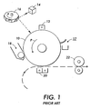
- FIG. 1 shows the basic elements by which a electrostatographic or xerographic printer, such as a copier or a "laser printer,” creates a dry-toner image on plain paper.
- a charge receptor such as photoreceptor 10, which may be in the form of a belt or drum, and which defines a charge-retentive surface for forming electrostatic images thereon.
- the photoreceptor 10 is caused to rotate through process direction P.
- the first step in the process is the general charging of the relevant photoreceptor surface.
- This initial charging is performed by a charge source such as a "scorotron," indicated as 12.
- the scorotron 12 typically includes an ion-generating structure, such as a hot wire, to impart an electrostatic charge on the surface of the photoreceptor 10 moving past it.
- the charged portions of the photoreceptor 10 are then selectively discharged in a configuration corresponding to the desired image to be printed, by a raster output scanner or ROS, which generally comprises a laser source 14 and a rotatable mirror 16 which act together, in a manner known in the art, to discharge certain areas of the surface of photoreceptor 10 according to a desired image to be printed.
- ROS raster output scanner
- FIG. 1 hows a laser 14 to selectively discharge the charge-retentive surface
- other apparatus that can be used for this purpose include an LED bar, or, in a copier, a light-lens system.
- the laser source 14 is modulated (turned on and off) in accordance with digital image data fed into it, and the rotating mirror 16 causes the modulated beam from laser source 14 to move in a fast-scan direction perpendicular to the process direction P of the photoreceptor 10.
- the remaining charged areas are developed by a developer unit such as 18, causing a supply of dry toner to contact or otherwise approach the surface of photoreceptor 10.
- the developed image is then advanced, by the motion of photoreceptor 10, to a transfer station 20, which causes the toner adhering to the photoreceptor 10 to be electrically transferred to a print sheet, which is typically a sheet of plain paper, to form the image thereon.
- the sheet of plain paper, with the toner image thereon is then passed through a fuser 22, which causes the toner to melt, or fuse, into the sheet of paper to create the permanent image.
- FIG. 2 is a detailed elevational view of the portion of the photoreceptor 10 between the developer unit 18 and the transfer station 20.
- the developer unit 18 includes a magnetic roll formed by a sleeve 30 which rotates, as shown by direction D, around an assembly including any number of fixed permanent magnets 32.
- the fields of the various magnets 32 through the sleeve 30 act to convey developer, in the form of a magnetic brush (not shown), toward the photoreceptor 18.
- the zone between the sleeve 30 and photoreceptor 10 where the magnetic brush provides toner particles to develop a latent image on photoreceptor 10 is known as a "development zone.”
- the illustrated embodiment includes the photoreceptor 10 and the sleeve 30 of the magnetic roll moving in opposite directions within the development zone, as shown by the arrows in FIG. 2. Also visible in the Figure is a "trim bar" 40, which is placed upstream of the development zone in the direction of rotation D of sleeve 30. Trim bar 40 trims the height of a magnetic brush of developer as the brush enters the development zone.
- the height of the magnetic brush created on the magnetic roll is in a suitable range relative to the total spacing between the magnetic roll and the photoreceptor in the development zone, in an arrangement where the magnetic roll and photoreceptor move in opposite directions, an air flow is created between the photoreceptor 10 and the sleeve 30 in a direction against the process direction P of the photoreceptor 18.
- This air flow, or "boundary air stream,” along the surface of photoreceptor 10 is useful for preventing airborne or otherwise stray toner particles from migrating down the process direction and, for instance, contaminating the transfer station 20, which could result in unintended marks on the transferred image or on the back of the print sheet.
- this boundary air stream is disrupted. If, for instance, there is a temporary condition of a high T/C (toner to carrier) ratio or low triboelectric levels in the development unit 18, the magnetic brush in the development zone itself disrupts the boundary air stream around the photoreceptor 10. If the boundary air stream ist hus disrupted, airborne or stray toner particles can move to contaminate the transfer station 20.
- T/C toner to carrier
- a simple N/S permanent magnetic strip 50 which extends across photoreceptor 10 in a direction perpendicular to process direction P, is provided.
- Strip 50 by virtue of its magnetic fields, maintains a bipolar brush between the development zone and the transfer station 20.
- the brush of carrier created by strip 50 acts as an air-permeable seal allowing air flow towards the development zone while preventing contaminated air from escaping downward to the transfer station 20.
- the brush formed on strip 50 itself remains clean and does not fail due to a build up of toner within it.
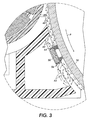
- FIG. 3 is a further detailed elevational view of a zone between the development zone and the transfer station in the embodiment of FIG. 2, showing a typical pattern of air flows, indicated by arrows, induced by the behavior of the magnetic strip 50.
- the magnetic strip 50 is disposed fairly close to the surface of photoreceptor 10; one or more small brushes of carrier particles, such as indicated as 54 and 56 is thus maintained in contact with the surface of photoreceptor 10.
- Each small brush acts to restrict airflow therethrough, in effect acting as a barrier substantially, but not necessarily completely, separating a circulating flow 60 of "dirty" (laden with airborne toner particles) air upstream of the strip 50 in the process direction P, and a circulating flow 62 of "clean" air downstream of the strip 50 in the process direction P.
- the dominant behavior of the air is to enter the zone below strip 50 against process direction P of photoreceptor 10; however, a boundary layer of air immediately adjacent the surface of photoreceptor 10 is often flowing with the process direction P.
- One or more poles associated with a magnetic strip such as 50 can be placed in c lose proximity t o the p hotoreceptor 10, although in one practical embodiment such as illustrated in FIG. 3, only the N pole faces the photoreceptor 10.
- this single pole facing the photoreceptor results in two brushes of carrier particles, indicated as 54 and 56; in other implementations, other configurations of magnetic poles will result in one or more brushes of various characteristics.
- what small airflow as can pass through brushes 54 and 56 is largely in the upstream direction, against the direction of a boundary layer of air around the moving photoreceptor 10.
- FIG. 4 is an elevational view of a structure adjacent the zone between the development zone and the transfer station in the embodiment of FIG. 2, showing alternate locations of a strip such as 50, in FIG. 4 shown as 50a, 50b, and 50c.
- strip 50a is shown as being essentially at the edge of the development zone; 50b is shown as being spaced mainly inside a cavity 52 adjacent photoreceptor 10; and 50c is disposed close to the transfer station 20.
- each of the strips may define one or more poles adjacent the photoreceptor 10, to control the position and behavior of one or more brushes of carrier particles.
Landscapes
- Physics & Mathematics (AREA)
- General Physics & Mathematics (AREA)
- Magnetic Brush Developing In Electrophotography (AREA)
- Dry Development In Electrophotography (AREA)
- Cleaning In Electrography (AREA)
Abstract
Description
- The present invention relates to electrostatographic or xerographic printing systems.
- In the well-known process of electrostatographic printing, the most common type of which is known as "xerography," a charge retentive surface, typically known as a photoreceptor, is electrostatically charged, and then exposed to a light pattern of an original image to selectively discharge the surface in accordance therewith. The resulting pattern of charged and discharged areas on the photoreceptor form an electrostatic charge pattern, known as a latent image, conforming to the original image. The latent image is developed by contacting it with a finally divided electrostatically attractable powder known as "toner." Toner is held on the image areas by the electrostatic charge on the photoreceptor surface. Thus, a toner image is produced in conformity with a light image of the original being reproduced. The toner image may then be transferred to a substrate, such as paper, and the image affixed thereto to form a permanent record of the image to be reproduced.
- The step in the electrostatographic process in which the toner is applied to the latent image is known as "development." In any development system, a quantity of toner is brought generally into contact with the latent image, so that the toner particles will adhere or not adhere to various areas on the surface in conformity with the latent image. Many techniques for carrying out this development are known in the art. A number of such techniques require that the toner particles be evenly mixed with a quantity of "carrier." Generally speaking, toner plus carrier equals "developer." Typically, toner particles are extremely fine, and responsive to electric fields; carrier particles are relatively large and respond to magnetic fields.
- In a "magnetic brush" development system, the developer is exposed to magnetic fields, causing the carrier particles to form brush-like strands, much in the manner of iron filings when exposed to a magnetic field. The toner particles, in turn, are triboelectrically adhered to the carrier particles in the strands. What is thus formed is a brush of magnetic particles with toner particles adhering to the strands of the brush. The base of the brush is formed on a "magnetic roll," which is typically in the form of a sleeve rotating around a fixed arrangement of magnets: the toner and carrier form the brush on the outside of the sleeve, influenced by the fields of the magnets inside the sleeve. This magnetic brush is brought in contact with the electrostatic latent image, and under certain conditions the toner particles separate from the carrier particles and adhere as necessary to the photoreceptor.
- According to one aspect of the present invention, there is provided an electrostatographic printing apparatus, comprising a charge receptor defining a charge-retentive surface, the charge receptor being movable in a process direction; a development unit including a rotatable sleeve for conveying developer to a development zone adjacent a portion of the charge-retentive surface, the rotatable sleeve moving in a direction opposite the process direction in the development zone; and a nonmoving magnetic strip disposed downstream of the development zone. The magnetic strip is positioned to maintain a brush of carrier particles substantially directly thereon.
-
- FIG. 1 shows the basic elements of a xerographic printer.
- FIG. 2 is a detailed elevational view of the portion of the photoreceptor between the developer unit and the transfer station of the xerographic printer of FIG. 1.
- FIG. 3 is a further detailed elevational view of a zone between the development zone and the transfer station in the embodiment of FIG. 2.
- FIG. 4 is an elevational view of a structure adjacent the zone between the development zone and the transfer station, showing alternate locations of a magnetic strip.
-
- FIG. 1 shows the basic elements by which a electrostatographic or xerographic printer, such as a copier or a "laser printer," creates a dry-toner image on plain paper. There is provided in the printer a charge receptor such as
photoreceptor 10, which may be in the form of a belt or drum, and which defines a charge-retentive surface for forming electrostatic images thereon. Thephotoreceptor 10 is caused to rotate through process direction P. - The first step in the process is the general charging of the relevant photoreceptor surface. This initial charging is performed by a charge source such as a "scorotron," indicated as 12. The
scorotron 12 typically includes an ion-generating structure, such as a hot wire, to impart an electrostatic charge on the surface of thephotoreceptor 10 moving past it. The charged portions of thephotoreceptor 10 are then selectively discharged in a configuration corresponding to the desired image to be printed, by a raster output scanner or ROS, which generally comprises alaser source 14 and arotatable mirror 16 which act together, in a manner known in the art, to discharge certain areas of the surface ofphotoreceptor 10 according to a desired image to be printed. Although the Figure s hows alaser 14 to selectively discharge the charge-retentive surface, other apparatus that can be used for this purpose include an LED bar, or, in a copier, a light-lens system. Thelaser source 14 is modulated (turned on and off) in accordance with digital image data fed into it, and the rotatingmirror 16 causes the modulated beam fromlaser source 14 to move in a fast-scan direction perpendicular to the process direction P of thephotoreceptor 10. - After certain areas of the
photoreceptor 10 are discharged by thelaser source 14, the remaining charged areas are developed by a developer unit such as 18, causing a supply of dry toner to contact or otherwise approach the surface ofphotoreceptor 10. The developed image is then advanced, by the motion ofphotoreceptor 10, to atransfer station 20, which causes the toner adhering to thephotoreceptor 10 to be electrically transferred to a print sheet, which is typically a sheet of plain paper, to form the image thereon. The sheet of plain paper, with the toner image thereon, is then passed through afuser 22, which causes the toner to melt, or fuse, into the sheet of paper to create the permanent image. - FIG. 2 is a detailed elevational view of the portion of the
photoreceptor 10 between thedeveloper unit 18 and thetransfer station 20. In this embodiment, thedeveloper unit 18 includes a magnetic roll formed by asleeve 30 which rotates, as shown by direction D, around an assembly including any number of fixedpermanent magnets 32. The fields of thevarious magnets 32 through thesleeve 30 act to convey developer, in the form of a magnetic brush (not shown), toward thephotoreceptor 18. The zone between thesleeve 30 andphotoreceptor 10 where the magnetic brush provides toner particles to develop a latent image onphotoreceptor 10 is known as a "development zone." - The illustrated embodiment includes the
photoreceptor 10 and thesleeve 30 of the magnetic roll moving in opposite directions within the development zone, as shown by the arrows in FIG. 2. Also visible in the Figure is a "trim bar" 40, which is placed upstream of the development zone in the direction of rotation D ofsleeve 30. Trim bar 40 trims the height of a magnetic brush of developer as the brush enters the development zone. In practice, if the height of the magnetic brush created on the magnetic roll is in a suitable range relative to the total spacing between the magnetic roll and the photoreceptor in the development zone, in an arrangement where the magnetic roll and photoreceptor move in opposite directions, an air flow is created between thephotoreceptor 10 and thesleeve 30 in a direction against the process direction P of thephotoreceptor 18. This air flow, or "boundary air stream," along the surface ofphotoreceptor 10 is useful for preventing airborne or otherwise stray toner particles from migrating down the process direction and, for instance, contaminating thetransfer station 20, which could result in unintended marks on the transferred image or on the back of the print sheet. - Under certain circumstances, this boundary air stream is disrupted. If, for instance, there is a temporary condition of a high T/C (toner to carrier) ratio or low triboelectric levels in the
development unit 18, the magnetic brush in the development zone itself disrupts the boundary air stream around thephotoreceptor 10. If the boundary air stream ist hus disrupted, airborne or stray toner particles can move to contaminate thetransfer station 20. - To avoid such disruption of the boundary air stream, a simple N/S permanent
magnetic strip 50, which extends acrossphotoreceptor 10 in a direction perpendicular to process direction P, is provided.Strip 50, by virtue of its magnetic fields, maintains a bipolar brush between the development zone and thetransfer station 20. The brush of carrier created bystrip 50 acts as an air-permeable seal allowing air flow towards the development zone while preventing contaminated air from escaping downward to thetransfer station 20. As a result of reduced pressure near the development roll which generates an air flow counter to the process direction of thephotoreceptor 10, the brush formed onstrip 50 itself remains clean and does not fail due to a build up of toner within it. - FIG. 3 is a further detailed elevational view of a zone between the development zone and the transfer station in the embodiment of FIG. 2, showing a typical pattern of air flows, indicated by arrows, induced by the behavior of the
magnetic strip 50. Themagnetic strip 50 is disposed fairly close to the surface ofphotoreceptor 10; one or more small brushes of carrier particles, such as indicated as 54 and 56 is thus maintained in contact with the surface ofphotoreceptor 10. Each small brush acts to restrict airflow therethrough, in effect acting as a barrier substantially, but not necessarily completely, separating a circulatingflow 60 of "dirty" (laden with airborne toner particles) air upstream of thestrip 50 in the process direction P, and a circulatingflow 62 of "clean" air downstream of thestrip 50 in the process direction P. As can be seen by the arrows inflow 62, the dominant behavior of the air is to enter the zone belowstrip 50 against process direction P ofphotoreceptor 10; however, a boundary layer of air immediately adjacent the surface ofphotoreceptor 10 is often flowing with the process direction P. - One or more poles associated with a magnetic strip such as 50 can be placed in c lose proximity t o the
p hotoreceptor 10, although in one practical embodiment such as illustrated in FIG. 3, only the N pole faces thephotoreceptor 10. As can be seen in the Figure, this single pole facing the photoreceptor results in two brushes of carrier particles, indicated as 54 and 56; in other implementations, other configurations of magnetic poles will result in one or more brushes of various characteristics. In that implementation, what small airflow as can pass throughbrushes photoreceptor 10. - FIG. 4 is an elevational view of a structure adjacent the zone between the development zone and the transfer station in the embodiment of FIG. 2, showing alternate locations of a strip such as 50, in FIG. 4 shown as 50a, 50b, and 50c. (In any one practical embodiment, only one of the strips would be installed.) In particular,
strip 50a is shown as being essentially at the edge of the development zone; 50b is shown as being spaced mainly inside acavity 52adjacent photoreceptor 10; and 50c is disposed close to thetransfer station 20. In various embodiments, it is possible to include one or more of the alternately-positionedstrips strip 50 shown in Figure 2. Also, depending on a specific embodiment, each of the strips may define one or more poles adjacent thephotoreceptor 10, to control the position and behavior of one or more brushes of carrier particles.
Claims (8)
- An electrostatographic printing apparatus, comprising:a charge receptor defining a charge-retentive surface, the charge receptor being movable in a process direction;a development unit including a rotatable sleeve for conveying developer to a development zone adjacent a portion of the charge-retentive surface;the rotatable sleeve moving in a direction opposite the process direction in the development zone; anda nonmoving magnetic strip disposed downstream of the development zone, the magnetic strip being positioned to maintain a brush of carrier particles substantially directly thereon.
- The apparatus of claim 1, the magnetic strip extending across the charge-retentive surface in a direction perpendicular to the process direction.
- The apparatus of c laim 1, the m agnetic strip being positioned to maintain a brush of carrier particles in contact with the charge-retentive surface.
- The apparatus of claim 1, the brush of carrier particles substantially restricting an air flow.
- The apparatus of claim 1, the brush of carrier particles substantially forming a barrier to substantially separate a first air flow upstream of the magnetic strip and a second air flow downstream of the magnetic strip.
- The apparatus of claim 1, the magnetic strip defining at least one pole adjacent the charge receptor, the one pole resulting in two brushes of carrier particles between the magnetic strip and the photoreceptor.
- The apparatus of claim 1, the magnetic strip defining at least two poles adjacent the charge receptor.
- The apparatus of claim 1, further comprising a second magnetic strip disposed downstream of the development zone.
Applications Claiming Priority (4)
| Application Number | Priority Date | Filing Date | Title |
|---|---|---|---|
| US43389002P | 2002-12-16 | 2002-12-16 | |
| US433890P | 2002-12-16 | ||
| US10/426,077 US6876829B2 (en) | 2002-12-16 | 2003-04-29 | Xerographic printing system with magnetic seal between development and transfer |
| US426077 | 2003-04-29 |
Publications (2)
| Publication Number | Publication Date |
|---|---|
| EP1445659A2 true EP1445659A2 (en) | 2004-08-11 |
| EP1445659A3 EP1445659A3 (en) | 2011-06-01 |
Family
ID=32511478
Family Applications (1)
| Application Number | Title | Priority Date | Filing Date |
|---|---|---|---|
| EP03028766A Withdrawn EP1445659A3 (en) | 2002-12-16 | 2003-12-12 | Xerographic printing system with magnetic seal between development and transfer portions |
Country Status (5)
| Country | Link |
|---|---|
| US (1) | US6876829B2 (en) |
| EP (1) | EP1445659A3 (en) |
| JP (1) | JP2004199055A (en) |
| BR (1) | BR0306027A (en) |
| MX (1) | MXPA03011503A (en) |
Families Citing this family (4)
| Publication number | Priority date | Publication date | Assignee | Title |
|---|---|---|---|---|
| US7356292B2 (en) * | 2006-06-15 | 2008-04-08 | Xerox Corporation | Electrostatographic developer unit having multiple magnetic brush rolls with a magnetic restrictor for carrier particle emission control |
| US20090116878A1 (en) * | 2007-11-05 | 2009-05-07 | Xerox Corporation | Color switching architecture |
| US7919962B2 (en) * | 2007-11-20 | 2011-04-05 | Xerox Corporation | Magnet scanning device that scans a cylindrical magnet along a helical path |
| US20090232543A1 (en) * | 2008-03-14 | 2009-09-17 | Kabushiki Kaisha Toshiba | Developing device of image forming apparatus |
Citations (1)
| Publication number | Priority date | Publication date | Assignee | Title |
|---|---|---|---|---|
| US4676191A (en) | 1984-11-16 | 1987-06-30 | Oki Electric Industry Co., Ltd. | Development device |
Family Cites Families (17)
| Publication number | Priority date | Publication date | Assignee | Title |
|---|---|---|---|---|
| JPS53111738A (en) * | 1977-03-11 | 1978-09-29 | Toshiba Corp | Developing device of magnetic brush type |
| JPS56158357A (en) * | 1980-05-10 | 1981-12-07 | Ricoh Co Ltd | Developing device |
| US4697914A (en) * | 1982-06-30 | 1987-10-06 | Xerox Corporation | Toner containment method and apparatus |
| JPS5945469A (en) * | 1982-09-08 | 1984-03-14 | Fuji Xerox Co Ltd | Electrophotographic device |
| GB8315726D0 (en) * | 1983-06-08 | 1983-07-13 | Xerox Corp | Electrostatographic development apparatus |
| JPS6132874A (en) * | 1984-07-26 | 1986-02-15 | Fuji Xerox Co Ltd | Device for preventing developing device from toner cloud |
| JPH0623887B2 (en) * | 1987-03-31 | 1994-03-30 | 富士ゼロックス株式会社 | Development device |
| JP2853037B2 (en) * | 1988-08-29 | 1999-02-03 | 株式会社リコー | Image forming device |
| US4963930A (en) * | 1988-08-29 | 1990-10-16 | Ricoh Company, Ltd. | Developing apparatus capable of preventing leakage of a developer |
| US5081503A (en) * | 1991-02-04 | 1992-01-14 | Xerox Corporation | Compact magnetic bead pick-off device |
| US5138382A (en) * | 1991-03-27 | 1992-08-11 | Xerox Corporation | Apparatus and method for creating a developer housing seal via a curtain of carrier beads |
| JPH0511618A (en) * | 1991-07-04 | 1993-01-22 | Canon Inc | Developing device for image forming device |
| US5280323A (en) * | 1991-09-10 | 1994-01-18 | Xerox Corporation | Development apparatus employing magnetic field shapers |
| US5376997A (en) * | 1992-02-13 | 1994-12-27 | Konica Corporation | Rotating sleeve-type magnetic brush cleaning device |
| JPH0895388A (en) * | 1994-09-20 | 1996-04-12 | Minolta Co Ltd | Carrier recovering device |
| JPH1195557A (en) * | 1997-09-22 | 1999-04-09 | Toshiba Corp | Developing device |
| JP3588029B2 (en) * | 1999-04-09 | 2004-11-10 | 株式会社リコー | Electrophotographic image forming apparatus and process cartridge used therein |
-
2003
- 2003-04-29 US US10/426,077 patent/US6876829B2/en not_active Expired - Fee Related
- 2003-12-09 JP JP2003410084A patent/JP2004199055A/en active Pending
- 2003-12-11 MX MXPA03011503A patent/MXPA03011503A/en active IP Right Grant
- 2003-12-12 EP EP03028766A patent/EP1445659A3/en not_active Withdrawn
- 2003-12-15 BR BR0306027-6A patent/BR0306027A/en not_active IP Right Cessation
Patent Citations (1)
| Publication number | Priority date | Publication date | Assignee | Title |
|---|---|---|---|---|
| US4676191A (en) | 1984-11-16 | 1987-06-30 | Oki Electric Industry Co., Ltd. | Development device |
Also Published As
| Publication number | Publication date |
|---|---|
| JP2004199055A (en) | 2004-07-15 |
| US6876829B2 (en) | 2005-04-05 |
| BR0306027A (en) | 2004-08-31 |
| MXPA03011503A (en) | 2004-09-10 |
| EP1445659A3 (en) | 2011-06-01 |
| US20040114957A1 (en) | 2004-06-17 |
Similar Documents
| Publication | Publication Date | Title |
|---|---|---|
| US4660059A (en) | Color printing machine | |
| US5253016A (en) | Contaminant control for scavengeless development in a xerographic apparatus | |
| JP2004117600A (en) | Image forming device | |
| JPH11295943A (en) | Multicolor image forming device | |
| US5038177A (en) | Selective pre-transfer corona transfer with light treatment for tri-level xerography | |
| US6876829B2 (en) | Xerographic printing system with magnetic seal between development and transfer | |
| US5225880A (en) | System for removing agglomerates from a developed image on a photoreceptor using a vacuum | |
| EP0002914B1 (en) | Method of operating a xerographic copier of the transfer type | |
| US8953968B2 (en) | Air-bearing photoreceptor backer bar for eliminating transfer streaks | |
| JPH09212010A (en) | Image recorder and image recording method | |
| JP2003280389A (en) | Developing device | |
| EP1359473B1 (en) | Electrodynamic Transfer System | |
| JPH1026861A (en) | Multicolor image forming device | |
| JP4599236B2 (en) | Image forming apparatus | |
| JP4143258B2 (en) | Developing device and image forming apparatus using the developing device | |
| JPH07325452A (en) | Multicolor electrophotographic device | |
| JPH0627757A (en) | Toner image forming device | |
| JP3235408B2 (en) | Image forming device | |
| JP2004219741A (en) | Image forming device | |
| JP2001312126A (en) | Image forming device | |
| US5420672A (en) | Concept for prevention of scavengeless nip wire contamination with toner | |
| US5940667A (en) | Asymmetrical donor member voltage | |
| JPH08240972A (en) | Developing device | |
| JPH11338250A (en) | Electrophotographic device | |
| JPH05257387A (en) | Image forming device |
Legal Events
| Date | Code | Title | Description |
|---|---|---|---|
| PUAI | Public reference made under article 153(3) epc to a published international application that has entered the european phase |
Free format text: ORIGINAL CODE: 0009012 |
|
| AK | Designated contracting states |
Kind code of ref document: A2 Designated state(s): AT BE BG CH CY CZ DE DK EE ES FI FR GB GR HU IE IT LI LU MC NL PT RO SE SI SK TR |
|
| AX | Request for extension of the european patent |
Extension state: AL LT LV MK |
|
| PUAL | Search report despatched |
Free format text: ORIGINAL CODE: 0009013 |
|
| AK | Designated contracting states |
Kind code of ref document: A3 Designated state(s): AT BE BG CH CY CZ DE DK EE ES FI FR GB GR HU IE IT LI LU MC NL PT RO SE SI SK TR |
|
| AX | Request for extension of the european patent |
Extension state: AL LT LV MK |
|
| RIC1 | Information provided on ipc code assigned before grant |
Ipc: G03G 15/00 20060101AFI20040604BHEP Ipc: G03G 15/09 20060101ALI20110426BHEP |
|
| 17P | Request for examination filed |
Effective date: 20111201 |
|
| AKX | Designation fees paid |
Designated state(s): DE FR GB |
|
| 17Q | First examination report despatched |
Effective date: 20131114 |
|
| STAA | Information on the status of an ep patent application or granted ep patent |
Free format text: STATUS: THE APPLICATION IS DEEMED TO BE WITHDRAWN |
|
| 18D | Application deemed to be withdrawn |
Effective date: 20161105 |