EP1445732A2 - Formation de séquences vidéo tridimensionnelles avec un appareil de télé-imagerie sans balayage - Google Patents
Formation de séquences vidéo tridimensionnelles avec un appareil de télé-imagerie sans balayage Download PDFInfo
- Publication number
- EP1445732A2 EP1445732A2 EP04075220A EP04075220A EP1445732A2 EP 1445732 A2 EP1445732 A2 EP 1445732A2 EP 04075220 A EP04075220 A EP 04075220A EP 04075220 A EP04075220 A EP 04075220A EP 1445732 A2 EP1445732 A2 EP 1445732A2
- Authority
- EP
- European Patent Office
- Prior art keywords
- image
- phase offset
- range
- images
- phase
- Prior art date
- Legal status (The legal status is an assumption and is not a legal conclusion. Google has not performed a legal analysis and makes no representation as to the accuracy of the status listed.)
- Withdrawn
Links
Images


Classifications
-
- G—PHYSICS
- G06—COMPUTING OR CALCULATING; COUNTING
- G06T—IMAGE DATA PROCESSING OR GENERATION, IN GENERAL
- G06T7/00—Image analysis
- G06T7/50—Depth or shape recovery
- G06T7/521—Depth or shape recovery from laser ranging, e.g. using interferometry; from the projection of structured light
Definitions
- the invention relates generally to the field of digital image processing, and in particular to the formation of a three-dimensional image sequence from a moving image bundle captured from a scannerless range imaging system.
- U.S. Patent 4,935,616 (further described in the Sandia Lab News, vol. 46, No. 19, September 16, 1994) describes a scannerless range imaging system using either an amplitude-modulated high-power laser diode or an array of amplitude-modulated light emitting diodes (LEDs) to completely illuminate a target scene.
- An improved scannerless range imaging system that is capable of yielding color intensity images in addition to the 3D range images is described in commonly-assigned, U.S. Patent No. 6,349,174 entitled “Method and Apparatus for a Color Scannerless Range Imaging System".
- a scannerless range imaging system will be referred to as a "SRI system”.
- the SRI system In the formation of a three-dimensional image (which will herein refer to the combination of the intensity image and range image), the SRI system generates an "image bundle", which includes both the intensity image and a collection of phase offset images which are used to construct the range image.
- image bundle which includes both the intensity image and a collection of phase offset images which are used to construct the range image.
- the three-dimensional images formed by the SRI system are useful in a variety of applications. In computer graphics, they can be used to construct photorealistic virtual worlds. For example, a prospective buyer could navigate with six degrees of freedom (three degrees due to translation, and three due to rotation) within a photorealistic virtual model of a house that is for sale, the model generated by a collection of three-dimensional images. In forensics, a three-dimensional image permits metrology of the captured scene long after the real scene has been investigated. In computer vision, three-dimensional images from an SRI system can be used in place of the typical stereo imaging design to enhance robot navigation in situations that are dangerous, inaccessible, or costly to humans.
- three-dimensional video sequences i.e., three-dimensional image sequences indexed in time.
- three-dimensional video would allow filmmakers to easily incorporate computer graphics objects, such as cartoons or virtual actors, into a video sequence of a real scene in such a way to make the objects appear that they are naturally interacting with the real environment.
- Knowledge of the depth of objects in a video sequence could be used to aid deletion of objects from the video sequence, or modify lighting or other properties without requiring recapture.
- a three-dimensional video sequence could also enhance a viewer's experience by allowing the viewer to navigate with six degrees of freedom within the video.
- such a three-dimensional video sequence is beyond the scope of the current SRI system, because the SRI system is only capable of forming single three-dimensional images.
- the present invention is directed to overcoming one or more of the problems set forth above in connection with a scannerless range imaging system of the type comprising an illuminator for illuminating a scene with modulated illumination; an image modulating component for receiving and modulating the modulated illumination reflected from the scene; and an image capture element for capturing images output by the image modulating component, including a bundle of at least three phase offset images each incorporating a phase delay corresponding to the distance of objects in the scene from the illuminator, wherein each phase offset image also incorporates a phase offset distinct for each image.
- a method for generating a range video sequence from such a scannerless range imaging system as described above comprises the steps of defining a frame rate, wherein the frame rate is the number of frames of the range video sequence per unit of time; acquiring for each frame a sequence of three or more phase offset images corresponding to the modulated illumination reflected from the scene, whereby the sequence forms an image bundle; and computing for each of the image bundles a range image using phase offset images from the corresponding image bundle, thereby forming a range video sequence.
- a method for generating a range video sequence from such a scannerless range imaging system as described above comprises the steps of acquiring a sequence of three or more phase offset images corresponding to the modulated illumination reflected from the scene, whereby the sequence contains overlapping subsequences of successive phase offset images, each subsequence forming an image bundle; and computing for each of the subsequences a range image using phase offset images from the corresponding image bundle, thereby forming a range video sequence.
- This aspect of the present invention has the advantage of reducing the amount of storage required by utilizing the same phase offset images in the computation of more than one range image in the sequence. Furthermore, the preferred embodiment of the present invention has the advantage of reducing the computational requirement, allowing the range images to be computed in real time.
- FIG. 1 is a block diagram of a scannerless range imaging system of the type known in the prior art.
- FIG. 2 is a block diagram of a method, according to the present invention, of forming a range video sequence.
- FIGS. 3A and 3B are block diagrams illustrating an embodiment of the present invention.
- FIG. 4 is a block diagram of a method, according to the present invention, of forming a range video sequence from a moving image bundle.
- FIGS. 5A, 5B and 5C are block diagrams illustrating an embodiment of the present invention.
- range imaging devices employing laser illuminators and capture devices (including image intensifiers and electronic sensors) are well known, the present description will be directed in particular to elements forming part of, or cooperating more directly with, a method and/or system in accordance with the present invention. Elements not specifically shown or described herein may be selected from those known in the art. Certain aspects of the embodiments to be described may be provided in software. Given the system as shown and described according to the invention in the following materials, software not specifically shown, described or suggested herein that is useful for implementation of the invention is conventional and within the ordinary skill in such arts.
- an SRI camera 100 is shown as a laser radar that is used to illuminate a scene 102 and then to capture an image bundle comprising a minimum of three images of the scene 102.
- An illuminator 104 emits a beam of electromagnetic radiation whose amplitude is controlled by a modulator 106.
- the illuminator 104 is a laser device that includes an optical diffuser in order to effect a wide-field illumination and remove modal structure.
- the modulator 106 provides a sinusoidal modulation.
- the modulation frequency is sufficiently high (e.g., 12.5 MHz) to attain sufficiently accurate range estimates.
- the output beam 108 is directed toward the scene 102 and a reflected beam 110 is directed back toward a receiving section 112.
- the reflected beam 110 is a delayed version of the transmitted output beam 108 , with the amount of phase delay being a function of the distance of the scene 102 from the range imaging system.
- the reflected beam 110 strikes a photocathode 114 within an image intensifier 116 , thereby producing a modulated electron stream proportional to the input amplitude variations.
- the purpose of the image intensifier is not only to intensify the image, but also to act as a frequency mixer and shutter. Accordingly, the image intensifier 116 is connected to the modulator 106 , causing the gain of a microchannel plate 118 to modulate.
- the electron stream from the photocathode 114 strikes the microchannel plate 118 and is mixed with a modulating signal from the modulator 106.
- the modulated electron stream is amplified through secondary emission by the microchannel plate 118 .
- the intensified electron stream bombards a phosphor screen 120, which converts the energy into a visible light image.
- the intensified light image signal is captured by a capture mechanism 122, such as a charge-coupled device (CCD).
- CCD charge-coupled device
- the captured image signal is applied to a range processor 124 to determine the phase delay at each point in the scene.
- phase term ⁇ is not directly accessible from a single image.
- equation (6) there are three unknown values and the form of the equation is quite simple.
- an image bundle shall be understood to include a collection of images which are of the same scene, but with each image having a distinct phase offset obtained from the modulation applied to the intensifier 116.
- the image bundle may also include the estimated range image, and any intensity (including color, as described in the aforementioned U.S. Patent No. 6,349,174, which is incorporated by reference herein) image of the same scene. It should also be understood that an analogous analysis can be performed by phase shifting the illuminator 104 instead of the intensifier 116 . If an image bundle comprising more than three images is captured, then the estimates of range can be enhanced by a least squares analysis using a singular value decomposition (see, e.g., W.H. Press, B.P. Flannery, S.A. Teukolsky and W.T. Vetterling, Numerical Recipes (the Art of Scientific Computing ), Cambridge University Press, Cambridge, 1986).
- the present invention generates a range video sequence from a sequence of image bundles captured by a scannerless range imaging system.
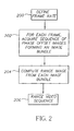
- the frame rate for the video sequence is defined.
- the frame rate is the number of frames, or images, in the video sequence per unit of time. For example, some typical frame rates used in the motion picture industry are 29.97 frames/second for NTSC video, 25 frames/second for PAL video, and 24 frames/second for film.
- each frame can be thought of as associated with an image bundle.
- an image bundle must contain at least three phase offset images, and all of the phase offset values must be distinct.
- a range image is computed from the corresponding image bundle, using the technique mentioned in the description of Figure 1.
- the computed range images at each frame form a range video sequence, as indicated by block 206 . If the intensity images corresponding to each range image are included, then the computed range images augmented with intensity data form three dimensional images, and the video sequence is a three-dimensional video sequence.
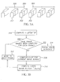
- the step 202 of acquiring a sequence of phase offset images for each frame is described with respect to an embodiment of the present invention.
- the frames 300 of the video sequence are spaced with a frequency defined by the frame rate 200.
- an image bundle 302 comprising a set of three or more distinct phase offset images is acquired.
- each range image in the sequence can be computed successively. Not including the operations required to form the pseudoinverse of the ( n ⁇ 3) matrix, this method requires 2 n multiplications, 2 n - 2 additions, and one arctangent evaluation per pixel.
- Figure 3B an embodiment of the step 204 of computing a range image from each image bundle is described.
- the matrix B may be pre-computed for the range video sequence and used repeatedly for computing each range image.
- H could be computed by singular value decomposition, QR decomposition, Moore-Penrose pseudoinverse, or any other technique known in the art.
- a query 306 is made as to whether range images have been computed for each frame. An affirmative response to query 306 indicates that the process has yielded the range video sequence 314 . A negative response to query 306 indicates that the range image must be computed for the current frame.
- a range image sequence is generated from a sequence of phase offset images captured by a scannerless range imaging system.
- the sequence of phase offset images acquired in step 400 has the special property that it contains overlapping subsequences of successive phase offset images, where each subsequence forms an image bundle. As was previously mentioned, an image bundle must contain at least three phase offset images, and all of the phase offset values must be distinct.
- the moving image bundle is initialized to be the image bundle containing the phase offset images in the first subsequence A 0 , with their corresponding phase offset values.
- a moving image bundle is an image bundle, where the phase offset images (and corresponding phase offset values) change when the moving image bundle is incremented, successively moving from one overlapping subsequence A j to the next A j+1 .
- a range image is computed from the phase offset images of the moving image bundle, using the technique mentioned in the description of Figure 1.
- the range image is labeled R 0 .
- a query 406 is made as to whether all range images in the sequence have been computed.
- a negative response to query 406 indicates that the moving bundle is incremented 408.
- the step 408, query 406, and step 404 are successively repeated, generating range images R 1 , R 2 ... , R n-1 , until an affirmative response to query 406 is received.
- the response to query 406 must be affirmative.
- An affirmative response to query 406 indicates that all range images have been computed, resulting in the formation of the range video sequence 410 .
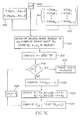
- the step 400 of acquiring a sequence of phase offset images is described with respect to the embodiment of Figure 4.
- the step 400 further comprises two steps.
- This particular choice of phase offsets will reduce the computational requirement of the step 404 of computing range images that is successively repeated, as will be seen in the description of Figure 5C.
- the new image bundle no longer contains phase offset image I j , but now contains phase offset image I j + k . Therefore, let be the k -vector that is equal to P, except in the ( j mod k ) th position, where it is instead equal to the code value at the pixel in phase offset image I j+k . Then it is easily seen that where e j mod k is the ( j mod k ) th column of the identity matrix, and H is the matrix given in the description of Figure 3A. Distributing H, we see this quantity is equal to which in turn is equal to where H , j mod k is the ( j mod k ) th column of H.
- This method of updating the intermediate images ⁇ 1 and ⁇ 2 and evaluating the arctangent can be performed iteratively to generate successive range images. If the first range image is computed using the classical method, then all successive range images only require two multiplications, three additions, and one arctangent evaluation per pixel. This allows for real time computation of the range image sequence, independent of the number of phase offset images used in each image bundle.
- step 512 the moving image bundle is initialized to A 0 514, and a range image R 0 is computed using the classical method presented in the description of Figure 1.
- the range image R 0 , and the intermediate images ⁇ 1 and ⁇ 2 are stored in memory.
- the matrix H described above, is computed.
- the counter j is incremented 526, and the process returns to query 518 .
- the moving image bundle is moved to contain the next subsequence 528, 530, etc., of phase offset images.
Landscapes
- Physics & Mathematics (AREA)
- Engineering & Computer Science (AREA)
- Optics & Photonics (AREA)
- Computer Vision & Pattern Recognition (AREA)
- General Physics & Mathematics (AREA)
- Theoretical Computer Science (AREA)
- Image Processing (AREA)
- Studio Devices (AREA)
- Image Analysis (AREA)
- Optical Radar Systems And Details Thereof (AREA)
- Length Measuring Devices By Optical Means (AREA)
Applications Claiming Priority (2)
| Application Number | Priority Date | Filing Date | Title |
|---|---|---|---|
| US10/360,380 US6856382B2 (en) | 2003-02-06 | 2003-02-06 | Formation of three-dimensional video sequences with a scannerless range imaging system |
| US360380 | 2003-02-06 |
Publications (2)
| Publication Number | Publication Date |
|---|---|
| EP1445732A2 true EP1445732A2 (fr) | 2004-08-11 |
| EP1445732A3 EP1445732A3 (fr) | 2005-02-16 |
Family
ID=32655653
Family Applications (1)
| Application Number | Title | Priority Date | Filing Date |
|---|---|---|---|
| EP04075220A Withdrawn EP1445732A3 (fr) | 2003-02-06 | 2004-01-26 | Formation de séquences vidéo tridimensionnelles avec un appareil de télé-imagerie sans balayage |
Country Status (4)
| Country | Link |
|---|---|
| US (1) | US6856382B2 (fr) |
| EP (1) | EP1445732A3 (fr) |
| JP (1) | JP2004240973A (fr) |
| IL (1) | IL159293A0 (fr) |
Families Citing this family (7)
| Publication number | Priority date | Publication date | Assignee | Title |
|---|---|---|---|---|
| BRPI0817990B1 (pt) * | 2007-09-24 | 2019-04-16 | Laser Technology, Inc. | Sistema unitário e método para integrar imagem e dados de determinação de velocidade. |
| WO2010026509A1 (fr) * | 2008-09-08 | 2010-03-11 | Koninklijke Philips Electronics, N.V. | Procédé et appareil pour la commande et la mesure d’aspects de lumière combinée variable dans le temps |
| KR101675112B1 (ko) * | 2010-01-21 | 2016-11-22 | 삼성전자주식회사 | 거리 정보 추출 방법 및 상기 방법을 채용한 광학 장치 |
| KR101722641B1 (ko) * | 2010-12-23 | 2017-04-04 | 삼성전자주식회사 | 3차원 영상 획득 장치 및 상기 3차원 영상 획득 장치에서 깊이 정보를 추출하는 방법 |
| WO2014178047A1 (fr) | 2013-04-30 | 2014-11-06 | Inuitive Ltd. | Système et procédé de vidéoconférence |
| DE102014106854A1 (de) * | 2014-05-15 | 2016-01-28 | Odos Imaging Ltd. | Bildgebendes System und Verfahren zum Überwachen eines Sichtfeldes |
| US11428786B2 (en) | 2017-12-03 | 2022-08-30 | Munro Design & Technologies, Llc | Dual waveforms for three-dimensional imaging systems and methods thereof |
Family Cites Families (12)
| Publication number | Priority date | Publication date | Assignee | Title |
|---|---|---|---|---|
| US3682553A (en) * | 1968-09-19 | 1972-08-08 | Optics Technology Inc | Apparatus for acquiring and laying real time 3-d information |
| US3604803A (en) * | 1969-03-03 | 1971-09-14 | Kollsman Instr Corp | Optical detection method for submerged objects |
| US3669541A (en) * | 1970-06-19 | 1972-06-13 | Bell Telephone Labor Inc | Direct display of light images with picosecond resolution |
| US3947119A (en) * | 1974-02-04 | 1976-03-30 | Ball Brothers Research Corporation | Active sensor automatic range sweep technique |
| US3899250A (en) * | 1974-02-04 | 1975-08-12 | Ball Brothers Res Corp | Active-gated television automatic range sweep technique |
| US4199253A (en) * | 1978-04-19 | 1980-04-22 | Solid Photography Inc. | Methods and systems for three-dimensional measurement |
| US4920412A (en) * | 1988-12-22 | 1990-04-24 | Sperry Marine Inc. | Atmospheric obscurant penetrating target observation system with range gating |
| US4935616A (en) | 1989-08-14 | 1990-06-19 | The United States Of America As Represented By The Department Of Energy | Range imaging laser radar |
| US6088086A (en) * | 1995-09-11 | 2000-07-11 | Sandia Corporation | Range determination for scannerless imaging |
| US6118946A (en) | 1999-06-29 | 2000-09-12 | Eastman Kodak Company | Method and apparatus for scannerless range image capture using photographic film |
| US6288776B1 (en) * | 1999-11-24 | 2001-09-11 | Eastman Kodak Company | Method for unambiguous range estimation |
| US6349174B1 (en) | 2000-05-17 | 2002-02-19 | Eastman Kodak Company | Method and apparatus for a color scannerless range imaging system |
-
2003
- 2003-02-06 US US10/360,380 patent/US6856382B2/en not_active Expired - Lifetime
- 2003-12-10 IL IL15929303A patent/IL159293A0/xx unknown
-
2004
- 2004-01-26 EP EP04075220A patent/EP1445732A3/fr not_active Withdrawn
- 2004-02-03 JP JP2004026952A patent/JP2004240973A/ja active Pending
Also Published As
| Publication number | Publication date |
|---|---|
| JP2004240973A (ja) | 2004-08-26 |
| US6856382B2 (en) | 2005-02-15 |
| US20040156034A1 (en) | 2004-08-12 |
| IL159293A0 (en) | 2005-11-20 |
| EP1445732A3 (fr) | 2005-02-16 |
Similar Documents
| Publication | Publication Date | Title |
|---|---|---|
| US7194112B2 (en) | Three dimensional spatial panorama formation with a range imaging system | |
| US6856355B1 (en) | Method and apparatus for a color scannerless range image system | |
| KR101854188B1 (ko) | 3차원 영상 획득 장치 및 3차원 영상 획득 장치에서 깊이 정보 산출 방법 | |
| US8139142B2 (en) | Video manipulation of red, green, blue, distance (RGB-Z) data including segmentation, up-sampling, and background substitution techniques | |
| JP6722194B2 (ja) | 深度フィールドイメージング装置、方法および応用 | |
| US20140353475A1 (en) | System and processor implemented method for improved image quality and enhancement based on quantum properties | |
| US20180204329A1 (en) | Generating a Distance Map Based on Captured Images of a Scene | |
| US20140168424A1 (en) | Imaging device for motion detection of objects in a scene, and method for motion detection of objects in a scene | |
| EP1580523A1 (fr) | Procede et dispositif permettant de mesurer une forme tridimensionnelle | |
| US20030048921A1 (en) | Method for embedding digital information in a three dimensional image from a scannerless range imaging system | |
| US6349174B1 (en) | Method and apparatus for a color scannerless range imaging system | |
| EP3832601B1 (fr) | Dispositif de traitement d'image et système de mesure tridimensionnelle | |
| CN105574847A (zh) | 相机系统及其图像配准方法 | |
| US12003874B2 (en) | Image sensors and sensing methods to obtain Time-of-Flight and phase detection information | |
| CN111292368B (zh) | 用于确定相对于飞行时间相机的深度运动的装置和方法 | |
| CN110517211A (zh) | 一种基于梯度域映射的图像融合方法 | |
| EP3757945A1 (fr) | Dispositif pour générer une image de réalité augmentée | |
| US6856382B2 (en) | Formation of three-dimensional video sequences with a scannerless range imaging system | |
| US6925195B2 (en) | Stabilization of three-dimensional images in a scannerless range imaging system | |
| CN108495113B (zh) | 用于双目视觉系统的控制方法和装置 | |
| JP2003114379A (ja) | 電気機械格子を用いたカラースキャナレスレンジ撮像システム | |
| JPH11257932A (ja) | 3次元リアルタイムセンサシステム | |
| EP3552044B1 (fr) | Appareil d'imagerie à temps de vol et procédé | |
| JPH08242469A (ja) | 撮像カメラ装置 | |
| JP2020042727A (ja) | 画像処理装置および画像処理方法、プログラム、並びに記憶媒体 |
Legal Events
| Date | Code | Title | Description |
|---|---|---|---|
| PUAI | Public reference made under article 153(3) epc to a published international application that has entered the european phase |
Free format text: ORIGINAL CODE: 0009012 |
|
| AK | Designated contracting states |
Kind code of ref document: A2 Designated state(s): AT BE BG CH CY CZ DE DK EE ES FI FR GB GR HU IE IT LI LU MC NL PT RO SE SI SK TR |
|
| AX | Request for extension of the european patent |
Extension state: AL LT LV MK |
|
| PUAL | Search report despatched |
Free format text: ORIGINAL CODE: 0009013 |
|
| AK | Designated contracting states |
Kind code of ref document: A3 Designated state(s): AT BE BG CH CY CZ DE DK EE ES FI FR GB GR HU IE IT LI LU MC NL PT RO SE SI SK TR |
|
| AX | Request for extension of the european patent |
Extension state: AL LT LV MK |
|
| AKX | Designation fees paid | ||
| REG | Reference to a national code |
Ref country code: DE Ref legal event code: 8566 |
|
| STAA | Information on the status of an ep patent application or granted ep patent |
Free format text: STATUS: THE APPLICATION IS DEEMED TO BE WITHDRAWN |
|
| 18D | Application deemed to be withdrawn |
Effective date: 20050817 |