EP1445736B1 - Verfahren und System zur Bereitstellung einer Volumendarstellung eines dreidimensionalen Objektes - Google Patents
Verfahren und System zur Bereitstellung einer Volumendarstellung eines dreidimensionalen Objektes Download PDFInfo
- Publication number
- EP1445736B1 EP1445736B1 EP04250603A EP04250603A EP1445736B1 EP 1445736 B1 EP1445736 B1 EP 1445736B1 EP 04250603 A EP04250603 A EP 04250603A EP 04250603 A EP04250603 A EP 04250603A EP 1445736 B1 EP1445736 B1 EP 1445736B1
- Authority
- EP
- European Patent Office
- Prior art keywords
- volumetric representation
- lines
- voxel
- images
- list
- Prior art date
- Legal status (The legal status is an assumption and is not a legal conclusion. Google has not performed a legal analysis and makes no representation as to the accuracy of the status listed.)
- Expired - Lifetime
Links
Images


Classifications
-
- G—PHYSICS
- G06—COMPUTING OR CALCULATING; COUNTING
- G06T—IMAGE DATA PROCESSING OR GENERATION, IN GENERAL
- G06T17/00—Three-dimensional [3D] modelling for computer graphics
-
- G—PHYSICS
- G06—COMPUTING OR CALCULATING; COUNTING
- G06T—IMAGE DATA PROCESSING OR GENERATION, IN GENERAL
- G06T17/00—Three-dimensional [3D] modelling for computer graphics
- G06T17/20—Finite element generation, e.g. wire-frame surface description, tesselation
-
- G—PHYSICS
- G06—COMPUTING OR CALCULATING; COUNTING
- G06T—IMAGE DATA PROCESSING OR GENERATION, IN GENERAL
- G06T7/00—Image analysis
- G06T7/50—Depth or shape recovery
- G06T7/55—Depth or shape recovery from multiple images
- G06T7/564—Depth or shape recovery from multiple images from contours
-
- G—PHYSICS
- G06—COMPUTING OR CALCULATING; COUNTING
- G06V—IMAGE OR VIDEO RECOGNITION OR UNDERSTANDING
- G06V10/00—Arrangements for image or video recognition or understanding
- G06V10/10—Image acquisition
-
- G—PHYSICS
- G06—COMPUTING OR CALCULATING; COUNTING
- G06V—IMAGE OR VIDEO RECOGNITION OR UNDERSTANDING
- G06V40/00—Recognition of biometric, human-related or animal-related patterns in image or video data
- G06V40/10—Human or animal bodies, e.g. vehicle occupants or pedestrians; Body parts, e.g. hands
- G06V40/103—Static body considered as a whole, e.g. static pedestrian or occupant recognition
-
- G—PHYSICS
- G06—COMPUTING OR CALCULATING; COUNTING
- G06V—IMAGE OR VIDEO RECOGNITION OR UNDERSTANDING
- G06V2201/00—Indexing scheme relating to image or video recognition or understanding
- G06V2201/12—Acquisition of 3D measurements of objects
Definitions
- the present invention relates to methods and systems for providing three-dimensional representations and will be described below with reference to this application. However, it will be appreciated that the invention is not limited to this particular field of use.
- Computer graphics processing can be highly computationally intensive, requiring large numbers of operations.
- the technical challenges of producing acceptable output in a reasonable time, particularly real time, are significant.
- An example of a method for providing volumetric representations of three-dimensional objects includes providing a three-dimensional (3D) shape reconstruction of objects from multiple views.
- the computation of the visual hull from object silhouettes is a popular technique.
- the method also called shape-from-silhouette, delivers a 3D description of the object.
- the approach requires a set of silhouette images from calibrated cameras.
- a silhouette image is a binary (or in some cases, grey scale) image where each pixel indicates whether this pixel belongs to the object or not.
- the silhouette information can be determined by any suitable segmentation process. This is advantageously done using chroma-keying or difference-keying as described in our GB-A-2393088 and our earlier applications referred therein.
- the 3D shape reconstruction can be formulated as the intersection of generalised cones of the silhouette images.
- a generalised cone is the union of visual rays from all silhouette points of a particular image. This intersection gives only an approximation of the real object shape and is called the visual hull. In particular concavities cannot be modelled with this method.
- a surface description usually a polygonal mesh has to be generated.
- An often used algorithm is the marching cubes algorithm, described in US Patent Nos. 4,710,876 and 4,885,688 , which creates an iso-surface of a volumetric data set. Since the mentioned shape-from-silhouette methods compute binary voxels the 3D surfaces generated from those using the marching cube algorithm are very noisy. This noise is introduced due to spatial discretisation of the volumetric representations. That is to say, real data as the actual shape of the object is lost during the processing of the algorithm.
- a method of modifying an approximate volumetric representation of a three-dimensional object comprising:
- the resultant modified volumetric representation of the object is more accurate than the approximate volumetric representation of the object.
- a resultant data set from the present invention that defines the volumetric representation of the object contains continuous data as to the shape of the object, rather than mere discrete data. Therefore, the resultant data set contains more realistic data defining the object.
- At least two two-dimensional images of the object are obtained and the object boundary positions are defined by edges of the object in the at least two two-dimensional images.
- the two-dimensional images provide a straightforward medium with which to define the object edges.
- the at least one set of lines is projected into at least one of the images to determine which of the lines intersect the edges.
- the line list of points is determined by the points where the lines intersection the edges, and the points are start and end points of line segments of the lines that intersect the edges.
- the data set of the line list of points is relatively small, compared with a complete data set of points defining the object in its entirety.
- the approximate volumetric representation is obtained by projecting the at least two images of the object into an array of voxels, determining in which of the voxel(s) one or more of the edge(s) of the object intersects therewith, and producing a voxel list thereof.
- the line list(s) are used to determine at least some locations on voxel edges of respective voxels in the voxel list to produce a voxel edge intersection list, and the voxel edge intersection list is used to produce the modified volumetric representation.
- the start and end points of the line segments are used to determine at least some locations on voxel edges of respective voxels in the voxel list to produce a voxel edge intersection list, and the voxel edge intersection list is used to produce the modified volumetric representation.
- Data for the modified volumetric representation may therefore be produced relatively efficiently.
- the modified volumetric representation is produced to have at least some voxel edges which more accurately match object edges than in the approximate representation.
- the approximate volumetric representation is obtained using a marching cubes procedure.
- the start and end points are used to modify the spatial positions of triangle vertices of triangles produced by the marching cubes procedure on the triangle vertices' respective voxel edges.
- the marching cubes procedure is efficient, the ability of the invention to modify the spatial positions of the triangle vertices allows for a comparatively more accurate representation of the object to be achieved.
- the data produced from the marching cubes procedure is discrete, data from the present invention is continuous, and therefore information regarding the object is not lost by comparison.
- the initial images are obtained using a plurality of said cameras in a studio, and the studio includes a retro-reflective background behind the object. The chroma-key process allows for ease of producing an image for use with the present invention.
- the start and end points and the position and direction of the lines are estimated with respect to a position of the camera when obtaining the images. Therefore, provided the location of each camera is known, it is not necessary for the cameras to be in the same position each time a volumetric representation is required.
- a texture map is applied to the volumetric representation.
- a method for providing a moving volumetric representation of an object comprising obtaining a plurality of volumetric representations of a three-dimensional object using the method of any one of the preceding statements, where each volumetric representation represents a different phase of movement of the object over time, and consecutively displaying each volumetric representation in a manner to produce to a viewer the sensation that the volumetric representation of the object is moving.
- a system for modifying an approximate volumetric representation of a three dimensional object comprising:
- the system includes means for obtaining at least two two-dimensional images of the object and the object boundary positions are defined by edges of the object in the at least two two-dimensional images.
- the system includes means for projecting the at least one set of lines into at least one of the images to determine which of the lines intersect the edges.
- the means for obtaining is at least one camera.
- the system comprises means for receiving a plurality of measures of positions of the at least one camera.
- the system comprises means for storing the plurality of measures of camera positions.
- An advantage of the present invention over the prior art is that it results in an ordered list stored over a 2D grid, and so simplifies processing in obtaining the volumetric representation of the object.
- a voxel is usually defined along orthogonal axes, typically of a cube, however it will be appreciated that for different applications of the invention, the voxels used may be of one or more different shapes, such as rectangular prism, tetrahedron, rhomboid, or of other three-dimensional polyhedron that are able to be part of an array where adjacent shapes share adjoining edges.
- the term voxel therefore, is not to be limited to any particular shape.
- a preferred embodiment of the present invention comprises a method of providing a volumetric representation of a three-dimensional object 20.
- Figure 1 an example of a person is given for the object 20.
- the object is not limited to people, but can be any object within reason.
- the method comprises several steps.
- the first step includes obtaining two dimensional (2D) binary, or silhouette images 22 of the object 20, using a camera & conventional chroma-keying techniques. In one embodiment, this is achieved using a multi-camera studio system with known camera parameters, as described in GB-A-2393088 .
- Figure 2 illustrates a chroma-key representation of one view of the object 20 in front of a retro-reflective background 18 illustrated in Figure 1 .
- six images of the object are preferably obtained from the chroma-keying, where the six images represent different side views of the object.
- the method may rely on two to five images, or more than six.
- Alternative techniques may also be used.
- fewer cameras or only one camera may be used taking several pictures of the object by either fixing the camera and rotating the object on a turntable or by moving the camera around the object. For the latter, a tracking system is needed that gives the camera parameters.
- a suitable system for this is described in GB-A-2325807 .
- FIG. 12 an example of a multi-camera studio system with known parameters is illustrated. Details of such components are described in GB-A-2325807 ; GB-A-2321814 and GB-A-2386489 .
- the system depicted in Figure 12 uses multiple cameras and chroma-key techniques to compute a 3D model of an actor 20.
- Studio cameras 23 are arranged to take images of the scene, including: at least one modified fixed camera 23a with an illuminator comprising a ring of blue LEDs for illuminating the object from the camera direction so that the retro-reflective background 18 reflects light back to the camera; and a similarly modified camera 23b with a tracking system.
- the next step is that of obtaining a line list of points using a computer.
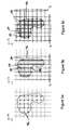
- This is achieved by sampling the object by a set of line segments 24, as illustrated in Figure 3 .
- the line segments 24 are organised into line segment sets S, organised in a 2D array.
- the line segments 24 illustrated in Figure 3 form a line segment set S(x 1 ,x 2 ) .
- the set S ( x 1 ,x 2 ) of segments 24 as illustrated in Figure 3 is only able to sample the surface of an object correctly along the continuous axis, i.e. in the direction of the line segments 24, or along x 3 .
- each position (m,n) may correspond to no line segments, or one or more line segments 24.
- Each line segment 24 is characterised by its start and end points 28 and 30 respectively.
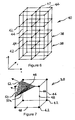
- a volume 32 is defined to surround the object 20.
- the volume is considered as entirely populated with one initial line segment for each column (m; n) covering the definition range 0 ⁇ x 3 ⁇ 3max of the volume.
- the entire algorithm for performing the step of projecting line segments into the silhouette images to determine the start and end points 28 and 30 for lines in each of the line sets is as follows:
- the line segments will be orthogonal to their respective plane from which they are projected, in a local line segment coordinate system.
- the line equations are: g m ⁇ n : ( ms x , ns y , 0 ⁇ ) T + ⁇ ( 0 , 0 , 1 ⁇ ) T where s x and s y are respective line spacings.
- the definition range for each line of the volume 32 in each of the Euclidian axes will be: for S yz , 0 ⁇ x ⁇ x max ; for S xz , 0 ⁇ y ⁇ y max ; and for S xy , 0 ⁇ z ⁇ z max .
- the next stage of the method involves obtaining an approximate volumetric representation of the object using a computer.
- the preferred form of this stage of the method is using the marching cubes procedure, or algorithm, as discussed above.
- other algorithms, or procedures may be used to obtain the approximate volumetric representation of the object in alternative embodiments.
- a marching triangles procedure may by used (''' Marching Triangles: Range Image Fusion for Complex Object Modelling" Hilton, 1., Stoddart, A.J., Ilingworth, J. and Windeatt, T. IEEE 1996 International Conference on Image Processing' .)
- the silhouette images 22 can then be thought of as being projected into the voxels' space, or vice versa. It is then determined in which of the voxels 38 the object 20 is present, and through which of the voxels an edge 46 of the object 20 passes. For the purpose of the specification, these latter voxels are termed "intersected voxels”. It is also determined through which of the voxel edges 44 the object edge 46 intersects.
- a list of the intersected voxels and their intersected edges (in terms of the voxel vertices 42 which define the respective voxel edge 44) is then compiled. This data is run through the remainder of the marching cubes algorithm, which firstly assumes the object edge 46 passes through a midpoint 48 of the voxel edge 44, and then reads a look-up table of fifteen variations of triangles having their vertices at the voxel edge midpoints 48 between adjacent voxel vertices and assigns one or two appropriate triangles to the given intersected voxel.
- an edge of an object has passed between voxel vertices 42a-d, or through voxel edges 44a-c.
- the object edge 46 may have intersected edges 44a-c at any point along the edges, the marching cubes algorithm assigns this voxel a triangle 50 with vertices 52 at edge midpoints 48.
- the triangles 50 which make up the volumetric representation have their vertices at respective voxel edge midpoints 48.
- data from the line segment sets S is used to determine, where appropriate, where on the intersected voxels' edges the object edge 46 actually passes. That is to say, when calculating the triangle to be used in a particular intersected voxel, the positions of the triangle vertices 52 are retrieved from the line segment sets with the same orientation as the particular voxel edges 44 and are therefore based on a measured value, rather than a mere discrete value, as is the case with the marching cubes algorithm.
- Figure7 illustrates the triangle 50 produced by the marching cubes algorithm, with midpoint vertices 52, whereas triangle 50a, corresponding to triangle 50, has vertices 52 at points not necessarily being voxel edge midpoints 48.
- Figure 8a illustrates the outcome of the marching cubes algorithm in one plane, of the object 20 illustrated in Figures 5a-c .
- voxel vertices 42 shown in bold are deemed within the object 20.
- the edge 44a of the marching cubes representation 54 passes through voxel edge midpoints 48.
- Figure 8b illustrates the use of two line sets Sxz and Syz which have been projected through plane xy, determining start and end points 28 and 30 of the line segments 24. These start and end points 28 and 30 show how the resultant representation 56 is a more accurate representation than when produced by the marching cubes algorithm alone.
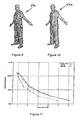
- Figure 9 represents a marching cubes volumetric representation 54a of the object 20 in Figure 1
- Figure 10 represents a volumetric representation 54b using the method of the present invention of the same object.
- Figures 9 and 10 it is apparent that the method of the present invention has produced a more accurate representation of the object 20.
- the number of triangles is shown over the measured model silhouette error.
- the computed 3D volumetric representation is projected into the original image.
- the silhouette error is then computed as the ratio between the number of pixels where the model is incorrect and the total number of pixels of the real object silhouette.
- the required number of triangles which is controlled by increasing or decreasing the voxel size of the volumetric data set is depicted for three methods: using discrete voxels; using a line segment set in just one direction and for 3 line segment sets.
- the prior art approach needs 8144 triangles.
- Our 3-line segment set approach needs only 3586 triangles.
- the 1-line segment set approach is only occasionally better than the prior art approach because it gains only in one direction from the line segment representation and introduces the same quantisation noise as the prior art method in the other directions.
- the computation for the 3D polygon models with an error of 8% needs 1.45 seconds for the conventional methods, 0.49 seconds for the 1 line segment set S and 0.52 seconds for three line segment sets, on a computer using a Linux ® operating system with a Pentium ® IV Xeon ® processor, running at 2.2 GHz.
- texture maps can be applied to the outcome of the method of the present invention to render a more realistic representation of the object 20.
- another embodiment of the present invention provides a moving volumetric representation of the object.
- a plurality of volumetric representations of the three-dimensional object 20 are obtained using the method of the first described embodiment, where each volumetric representation represents a different phase of movement of the object 20 over time.
- the volumetric representations are displayed, usually on a computer, over time to produce to a viewer the sensation that the volumetric representation of the object is moving.
- Another preferred embodiment of the invention provides a system for providing a volumetric representation of a three dimensional object 20.
- the system comprises means for obtaining silhouette images of the object, the means being in the form of a camera and conventional chroma-key imaging equipment.
- the system also includes means for obtaining a line list of points of at least one set of lines having start and end points corresponding to intersection of the lines with object boundary positions; means for obtaining an approximate volumetric representation of the object; and means for producing a modified volumetric representation based on the start and end points of the set of lines.
- These means are in the form of a computer with software to process the line list, and obtain an approximate representation, according to the methods described above.
- the chroma-key imaging equipment is capable of providing digital information of the silhouette images 22 to the computer with software to process the line list.
- the chroma-key imaging equipment only produces a printed copy of the silhouette images, these images are scanned using a conventional scanner to provide the digital information of the silhouette images 22.
- the start and end points of the lines may be used to form a continuous surface. This may be achieved by beginning with one of the start or end points and searching for adjacent, or neighboring points to form a polygon.
- a 3D search may be performed, but an advantage of this method is that, because the lines are arranged in 2D grids, a more efficient 2D neighboring point search may be performed.
- the search along two grid axes in the plane of the grid may be used to locate the 3D coordinates of the neighboring start or end point. For example, with reference to Figure 3 , A search along the x1 ,x2 axes will enable start and end points of the lines to be correlated into lower and upper bounding triangles.
- the invention provides a method of providing a volumetric representation of a three-dimensional object.
- the method comprises several steps, including obtaining a line list of points of at least one set of lines having start and end points corresponding to intersection of the lines with object boundary positions and obtaining an approximate volumetric representation of the object.
- a modified volumetric representation is produced by modifying the approximate volumetric representation based on the start and end points of the set of lines and the approximate volumetric representation.
- the resultant modified volumetric representation of the object is more accurate than the approximate volumetric representation of the object.
- a resultant data set from the present invention that defines the volumetric representation of the object contains continuous data as to the shape of the object, rather than mere discrete data. Therefore, the resultant data set contains more realistic data defining the object.
Landscapes
- Engineering & Computer Science (AREA)
- Physics & Mathematics (AREA)
- General Physics & Mathematics (AREA)
- Theoretical Computer Science (AREA)
- Computer Graphics (AREA)
- Geometry (AREA)
- Software Systems (AREA)
- Multimedia (AREA)
- Computer Vision & Pattern Recognition (AREA)
- Human Computer Interaction (AREA)
- Image Processing (AREA)
- Image Generation (AREA)
Claims (26)
- Verfahren zum Modifizieren einer approximativen volumetrischen Darstellung eines dreidimensionalen Objekts, wobei das Verfahren umfasst:Erhalten einer Linienliste von Punkten von wenigstens eine Menge von Linien mit Start- und Endpunkten, die dem Schnittpunkt der Linien mit Objektgrenzen-Positionen entsprechen;wobei die Mengen von Linien Komponenten besitzen, die sich in drei orthogonalen Richtungen erstrecken; und
Erzeugen einer modifizierten volumetrischen Darstellung durch Modifizieren der approximativen volumetrischen Darstellung anhand der Start- und Endpunkte der Menge von Linien und der approximativen volumetrischen Darstellung. - Verfahren nach Anspruch 1, bei dem die Linienlisten von Punkten kontinuierliche Datenwerte enthalten.
- Verfahren nach Anspruch 1 oder Anspruch 2, bei dem wenigstens zwei zweidimensionale Bilder des Objekts erhalten werden und die Objektgrenzen-Positionen durch Kanten des Objekts in den wenigstens zwei zweidimensionalen Bildern definiert sind.
- Verfahren nach einem vorhergehenden Anspruch, bei dem wenigstens eine Menge von Linien auf wenigstens eines der Bilder projiziert wird, um zu bestimmen, welche der Linien die Kanten schneiden.
- Verfahren nach einem vorhergehenden Anspruch, bei dem die Linienliste von Punkten durch die Punkte bestimmt ist, an denen die Linien die Kanten schneiden.
- Verfahren nach einem der Ansprüche 3 bis 5, bei dem die approximative volumetrische Darstellung erhalten wird durch Projizieren der wenigstens zwei Bilder des Objekts auf eine Voxel-Matrix, durch Bestimmen, in welchem Voxel bzw. in welchen Voxels eine oder mehrere Kanten des Objekts sich damit schneiden, und durch Erzeugen einer Voxel-Liste hiervon.
- Verfahren nach Anspruch 6, bei dem die Linienliste(n) verwendet wird (werden), um wenigstens zwei Orte auf Voxel-Kanten entsprechender Voxels in der Voxelliste zu bestimmen, um eine Voxel-Kanten-Schnittpunktliste zu erzeugen, und bei dem die Voxel-Kanten-Schnittpunktliste verwendet wird, um die modifizierte volumetrische Darstellung zu erzeugen.
- Verfahren nach Anspruch 6, wenn abhängig von Anspruch 5, bei dem die Start- und Endpunkte der Liniensegmente verwendet werden, um wenigstens einige Orte auf Voxel-Kanten entsprechender Voxels in der Voxel-Liste zu bestimmen, um eine Voxel-Kanten-Schnittpunktliste zu erzeugen, und bei dem die Voxel-Kanten-Schnittpunktliste verwendet wird, um die modifizierte volumetrische Darstellung zu erzeugen.
- Verfahren nach einem der vorhergehenden Ansprüche, bei dem die approximative volumetrische Darstellung unter Verwendung einer Prozedur laufender Würfel (marching cubes procedure) erhalten wird.
- Verfahren nach Anspruch 9, bei dem die Start- und Endpunkte verwendet werden, um die räumlichen Positionen von Dreieck-Scheitelpunkten von Dreiecken zu modifizieren, die durch die Prozedur laufender Würfel an den entsprechenden Voxel-Kanten der Dreieck-Scheitelpunkte erzeugt werden.
- Verfahren nach einem der Ansprüche 2 bis 10, bei dem die Bilder aus einem Chroma-Key-Prozess erzeugt werden.
- Verfahren nach Anspruch 11, bei dem die anfänglichen Bilder unter Verwendung einer oder mehrerer Kameras in einem Studio erhalten werden.
- Verfahren nach Anspruch 12, bei dem das Studio einen zurückreflektierenden Hintergrund hinter dem Objekt enthält.
- Verfahren nach einem der Ansprüche 5 bis 13, bei dem die Start- und Endpunkte sowie die Position und die Richtung der Linien in Bezug auf eine Position der Kamera geschätzt werden, wenn die Bilder erhalten werden.
- Verfahren nach einem der Ansprüche 5 bis 14, das das Empfangen und/oder Speichern mehrerer Messwerte von Kamerapositionen umfasst.
- Verfahren nach einem der Ansprüche 5 bis 14, bei dem wenigstens eine Kameraposition dynamisch erhalten wird.
- Verfahren nach einem der Ansprüche 11 bis 16, das drei Paare von Bildern umfasst, wobei die Bilder jedes Paars in einer parallelen Ebene liegen und die Ebene jedes entsprechenden Bildes jedes Paars zu den Ebenen der verbleibenden Paare senkrecht ist.
- Verfahren nach einem der vorhergehenden Ansprüche, bei dem eine Texturkarte auf die volumetrische Darstellung angewendet wird.
- Verfahren zum Bereitstellen einer sich bewegenden volumetrischen Darstellung eines Objekts, wobei das Verfahren das Erhalten mehrerer volumetrischer Darstellungen eines dreidimensionalen Objekts unter Verwendung des Verfahrens nach einem der vorhergehenden Ansprüche umfasst, wobei jede volumetrische Darstellung eine unterschiedliche Phase der Bewegung des Objekts über die Zeit hinweg darstellt, und das aufeinander folgende Anzeigen jeder volumetrischen Darstellung in der Weise, dass für einen Beobachter die Empfindung erzeugt wird, dass sich die volumetrische Darstellung des Objekts bewegt, umfasst.
- System zum Modifizieren einer volumetrischen Darstellung eines dreidimensionalen Objekts, wobei das System umfasst:Mittel, um eine Linienliste von Punkten von wenigstens eine Menge von Linien mit Start- und Endpunkten, die dem Schnittpunkt der Linien mit Objektgrenzen-Positionen entsprechen, zu erhalten;wobei die Mengen von Linien Komponenten besitzen, die sich in drei orthogonalen Dimensionen erstrecken,
Mittel, um die Linienlisten von Punkten zu speichern; und
Mittel, um eine modifizierte volumetrische Darstellung anhand der Start- und Endpunkten der Menge von Linien zu erzeugen. - System nach Anspruch 20, das Mittel umfasst, um wenigstens zwei zweidimensionale Bilder des Objekts zu erhalten, wobei die Objektgrenzen-Positionen durch Kanten des Objekts in den wenigstens zwei zweidimensionalen Bildern definiert sind.
- System nach Anspruch 21, das Mittel umfasst, um die wenigstens eine Menge von Linien auf wenigstens eines der Bilder zu projizieren, um zu bestimmen, welche der Linien die Kanten schneiden.
- System nach Anspruch 21 oder 22, bei dem die Erhalte-Mittel wenigstens eine Kamera sind.
- System nach Anspruch 20, das Mittel umfasst, um mehrere Messwerte von Positionen der wenigstens einen Kamera zu empfangen.
- System nach Anspruch 21, das Mittel umfasst, um die mehreren Messwerte von Kamerapositionen zu speichern.
- Computerprogramm oder Computerprogrammprodukt, um eine volumetrische Darstellung eines dreidimensionalen Objekts zu schaffen, das Mittel umfasst, um das Verfahren nach einem der Ansprüche 1 bis 19 auszuführen, wenn es auf einem Computer ausgeführt wird.
Applications Claiming Priority (2)
| Application Number | Priority Date | Filing Date | Title |
|---|---|---|---|
| GB0302561 | 2003-02-04 | ||
| GB0302561A GB2399703B (en) | 2003-02-04 | 2003-02-04 | Method and system for providing a volumetric representation of a three-dimensional object |
Publications (3)
| Publication Number | Publication Date |
|---|---|
| EP1445736A2 EP1445736A2 (de) | 2004-08-11 |
| EP1445736A3 EP1445736A3 (de) | 2005-06-15 |
| EP1445736B1 true EP1445736B1 (de) | 2008-03-12 |
Family
ID=9952425
Family Applications (1)
| Application Number | Title | Priority Date | Filing Date |
|---|---|---|---|
| EP04250603A Expired - Lifetime EP1445736B1 (de) | 2003-02-04 | 2004-02-04 | Verfahren und System zur Bereitstellung einer Volumendarstellung eines dreidimensionalen Objektes |
Country Status (4)
| Country | Link |
|---|---|
| US (1) | US7209136B2 (de) |
| EP (1) | EP1445736B1 (de) |
| DE (1) | DE602004012341T2 (de) |
| GB (1) | GB2399703B (de) |
Families Citing this family (19)
| Publication number | Priority date | Publication date | Assignee | Title |
|---|---|---|---|---|
| CA2544909A1 (en) * | 2003-11-28 | 2005-06-09 | Bracco Imaging S.P.A. | Method and system for distinguishing surfaces in 3d data sets ("dividing voxels") |
| RU2276408C1 (ru) * | 2004-09-03 | 2006-05-10 | Самсунг Электроникс Ко., Лтд | Устройство и способ обработки трехмерного объекта с использованием функции возмущений |
| GB2418827B (en) | 2004-09-28 | 2010-11-10 | British Broadcasting Corp | Method and system for providing a volumetric representation of a 3-Dimensional object |
| KR100602594B1 (ko) | 2005-06-10 | 2006-07-19 | 주식회사 아이너스기술 | 3차원 측정 데이터의 분석 결과 재계산 시스템 및 방법 |
| KR100721536B1 (ko) * | 2005-12-09 | 2007-05-23 | 한국전자통신연구원 | 2차원 평면상에서 실루엣 정보를 이용한 3차원 구조 복원방법 |
| KR100753536B1 (ko) | 2006-05-04 | 2007-08-30 | 주식회사 아이너스기술 | 3차원 역설계 모델링을 위한 원시 모델 데이터로부터 2차원스케치 데이터를 검출하는 방법 |
| US7821513B2 (en) | 2006-05-09 | 2010-10-26 | Inus Technology, Inc. | System and method for analyzing modeling accuracy while performing reverse engineering with 3D scan data |
| JP5218034B2 (ja) * | 2008-12-26 | 2013-06-26 | Kddi株式会社 | マスク画像を抽出する方法及びプログラム並びにボクセルデータを構築する方法及びプログラム |
| US8774523B2 (en) * | 2009-07-28 | 2014-07-08 | Schlumberger Technology Corporation | Precise boundary segment intersection for boundary representation modeling |
| US8564617B2 (en) * | 2010-01-12 | 2013-10-22 | International Business Machines Corporation | Accelerated volume rendering |
| JP5574852B2 (ja) * | 2010-06-30 | 2014-08-20 | キヤノン株式会社 | 情報処理装置、情報処理方法、システム及びプログラム |
| US9111349B2 (en) * | 2011-12-16 | 2015-08-18 | Microsoft Technology Licensing, Llc | Object identification using 3-D curve matching |
| CN106611158A (zh) * | 2016-11-14 | 2017-05-03 | 深圳奥比中光科技有限公司 | 人体3d特征信息的获取方法及设备 |
| KR102122131B1 (ko) * | 2017-12-26 | 2020-06-11 | 주식회사 일루베이션 | 가축 무게 측정 시스템 및 이를 이용한 가축 무게 측정 방법 |
| KR102269532B1 (ko) * | 2019-04-19 | 2021-06-25 | 주식회사 일루베이션 | 3차원 이미지를 활용한 가축 무게 측정 시스템 및 이를 이용한 가축 무게 측정 방법 |
| KR102131559B1 (ko) * | 2019-05-27 | 2020-07-07 | 주식회사 일루베이션 | 건 타입 가축 무게 측정 장치 및 이를 이용한 가축 무게 측정 방법 |
| KR102131560B1 (ko) * | 2019-05-27 | 2020-07-07 | 주식회사 일루베이션 | 웨어러블 타입 가축 무게 측정 장치 및 이를 이용한 가축 무게 측정 방법 |
| KR102123761B1 (ko) * | 2019-06-20 | 2020-06-16 | 주식회사 일루베이션 | 3d 스캐닝을 이용한 3d 모델 분석 기반의 가축 추적 시스템 및 이의 가축 체중 예측 방법 |
| EP4584759A1 (de) | 2022-09-08 | 2025-07-16 | Digimarc Corporation | Bildanalyseverfahren und -anordnungen |
Family Cites Families (12)
| Publication number | Priority date | Publication date | Assignee | Title |
|---|---|---|---|---|
| US4710876A (en) | 1985-06-05 | 1987-12-01 | General Electric Company | System and method for the display of surface structures contained within the interior region of a solid body |
| US4885688A (en) | 1987-11-25 | 1989-12-05 | General Electric Company | Minimization of directed points generated in three-dimensional dividing cubes method |
| US5101475A (en) * | 1989-04-17 | 1992-03-31 | The Research Foundation Of State University Of New York | Method and apparatus for generating arbitrary projections of three-dimensional voxel-based data |
| US5442733A (en) * | 1992-03-20 | 1995-08-15 | The Research Foundation Of State University Of New York | Method and apparatus for generating realistic images using a discrete representation |
| US5548694A (en) * | 1995-01-31 | 1996-08-20 | Mitsubishi Electric Information Technology Center America, Inc. | Collision avoidance system for voxel-based object representation |
| GB2321814B (en) | 1997-01-28 | 2001-02-14 | British Broadcasting Corp | Video imaging |
| JPH10255081A (ja) * | 1997-03-10 | 1998-09-25 | Canon Inc | 画像処理方法及び画像処理装置 |
| GB2366463B (en) | 1997-05-30 | 2002-04-17 | British Broadcasting Corp | Position determination |
| US6674430B1 (en) * | 1998-07-16 | 2004-01-06 | The Research Foundation Of State University Of New York | Apparatus and method for real-time volume processing and universal 3D rendering |
| US6489961B1 (en) * | 2000-10-17 | 2002-12-03 | Actuality Systems, Inc. | Rasterization of lines in a cylindrical voxel grid |
| GB0117157D0 (en) * | 2001-07-16 | 2001-09-05 | Imec Inter Uni Micro Electr | Extraction, hierarchical representation and flexible compression of surface meshes derived from 3D data |
| US20030151604A1 (en) * | 2001-11-21 | 2003-08-14 | Research Foundation Of State University Of New York | Volume rendering with contouring texture hulls |
-
2003
- 2003-02-04 GB GB0302561A patent/GB2399703B/en not_active Expired - Lifetime
-
2004
- 2004-02-04 US US10/773,042 patent/US7209136B2/en not_active Expired - Fee Related
- 2004-02-04 DE DE602004012341T patent/DE602004012341T2/de not_active Expired - Lifetime
- 2004-02-04 EP EP04250603A patent/EP1445736B1/de not_active Expired - Lifetime
Also Published As
| Publication number | Publication date |
|---|---|
| GB2399703B (en) | 2006-09-27 |
| DE602004012341T2 (de) | 2009-03-12 |
| GB0302561D0 (en) | 2003-03-12 |
| DE602004012341D1 (de) | 2008-04-24 |
| GB2399703A (en) | 2004-09-22 |
| EP1445736A3 (de) | 2005-06-15 |
| US20050035961A1 (en) | 2005-02-17 |
| EP1445736A2 (de) | 2004-08-11 |
| US7209136B2 (en) | 2007-04-24 |
Similar Documents
| Publication | Publication Date | Title |
|---|---|---|
| EP1445736B1 (de) | Verfahren und System zur Bereitstellung einer Volumendarstellung eines dreidimensionalen Objektes | |
| EP1640915B1 (de) | Verfahren und System für die volumetrische Darstellung eines dreidimensionalen Objekts | |
| US6791540B1 (en) | Image processing apparatus | |
| US7046840B2 (en) | 3-D reconstruction engine | |
| EP0638875B1 (de) | Verfahren und Gerät zur Erzeugung von dreidimensionaler Animation | |
| US6518963B1 (en) | Method and apparatus for generating patches from a 3D mesh model | |
| US6970591B1 (en) | Image processing apparatus | |
| Newcombe et al. | Live dense reconstruction with a single moving camera | |
| US6999073B1 (en) | Method and system for generating fully-textured 3D | |
| US6990228B1 (en) | Image processing apparatus | |
| CN113706714A (zh) | 基于深度图像和神经辐射场的新视角合成方法 | |
| EP1271411A2 (de) | Bildbasiertes hierarchisches Gerät und Verfahren zur Wiedergabe und Darstellung von dreidimensionalen Objekten | |
| US6317139B1 (en) | Method and apparatus for rendering 3-D surfaces from 2-D filtered silhouettes | |
| Agrawal et al. | A probabilistic framework for surface reconstruction from multiple images | |
| JP2001067463A (ja) | 異なる視点からの複数のフェイシャル画像に基づき新たな視点からのフェイシャル画像を生成するフェイシャル画像生成装置及び方法並びにその応用装置及び記録媒体 | |
| CN120355848B (zh) | 一种场景表面重建方法、装置、设备及介质 | |
| US7280685B2 (en) | Object segmentation from images acquired by handheld cameras | |
| Wilson et al. | Simplifying complex environments using incremental textured depth meshes | |
| Schmitt et al. | 3d color object reconstruction from 2d image sequences | |
| Erol et al. | Visual Hull Construction Using Adaptive Sampling. | |
| Pulli et al. | Surface modeling and display from range and color data | |
| US5821942A (en) | Ray tracing through an ordered array | |
| GB2365243A (en) | Creating a 3D model from a series of images | |
| GB2358307A (en) | Method of determining camera projections in 3D imaging having minimal error | |
| WO2011080669A1 (en) | System and method for reconstruction of range images from multiple two-dimensional images using a range based variational method |
Legal Events
| Date | Code | Title | Description |
|---|---|---|---|
| PUAI | Public reference made under article 153(3) epc to a published international application that has entered the european phase |
Free format text: ORIGINAL CODE: 0009012 |
|
| AK | Designated contracting states |
Kind code of ref document: A2 Designated state(s): AT BE BG CH CY CZ DE DK EE ES FI FR GB GR HU IE IT LI LU MC NL PT RO SE SI SK TR |
|
| AX | Request for extension of the european patent |
Extension state: AL LT LV MK |
|
| REG | Reference to a national code |
Ref country code: DE Ref legal event code: R079 Ref document number: 602004012341 Country of ref document: DE Free format text: PREVIOUS MAIN CLASS: G06T0017200000 Ipc: G06T0017100000 |
|
| PUAL | Search report despatched |
Free format text: ORIGINAL CODE: 0009013 |
|
| RIC1 | Information provided on ipc code assigned before grant |
Ipc: 7G 06T 17/20 B Ipc: 7G 06T 17/10 A |
|
| AK | Designated contracting states |
Kind code of ref document: A3 Designated state(s): AT BE BG CH CY CZ DE DK EE ES FI FR GB GR HU IE IT LI LU MC NL PT RO SE SI SK TR |
|
| AX | Request for extension of the european patent |
Extension state: AL LT LV MK |
|
| 17P | Request for examination filed |
Effective date: 20051215 |
|
| AKX | Designation fees paid |
Designated state(s): BE DE FR GB IT |
|
| GRAP | Despatch of communication of intention to grant a patent |
Free format text: ORIGINAL CODE: EPIDOSNIGR1 |
|
| GRAS | Grant fee paid |
Free format text: ORIGINAL CODE: EPIDOSNIGR3 |
|
| 17Q | First examination report despatched |
Effective date: 20060131 |
|
| GRAA | (expected) grant |
Free format text: ORIGINAL CODE: 0009210 |
|
| AK | Designated contracting states |
Kind code of ref document: B1 Designated state(s): BE DE FR GB IT |
|
| REG | Reference to a national code |
Ref country code: GB Ref legal event code: FG4D |
|
| REF | Corresponds to: |
Ref document number: 602004012341 Country of ref document: DE Date of ref document: 20080424 Kind code of ref document: P |
|
| REG | Reference to a national code |
Ref country code: DE Ref legal event code: R096 Ref document number: 602004012341 Country of ref document: DE Effective date: 20080424 |
|
| ET | Fr: translation filed | ||
| PLBE | No opposition filed within time limit |
Free format text: ORIGINAL CODE: 0009261 |
|
| STAA | Information on the status of an ep patent application or granted ep patent |
Free format text: STATUS: NO OPPOSITION FILED WITHIN TIME LIMIT |
|
| 26N | No opposition filed |
Effective date: 20081215 |
|
| REG | Reference to a national code |
Ref country code: DE Ref legal event code: R097 Ref document number: 602004012341 Country of ref document: DE Effective date: 20081215 |
|
| PGFP | Annual fee paid to national office [announced via postgrant information from national office to epo] |
Ref country code: IT Payment date: 20120215 Year of fee payment: 9 |
|
| PGFP | Annual fee paid to national office [announced via postgrant information from national office to epo] |
Ref country code: DE Payment date: 20130219 Year of fee payment: 10 Ref country code: GB Payment date: 20130226 Year of fee payment: 10 Ref country code: FR Payment date: 20130318 Year of fee payment: 10 |
|
| PGFP | Annual fee paid to national office [announced via postgrant information from national office to epo] |
Ref country code: BE Payment date: 20130301 Year of fee payment: 10 |
|
| BERE | Be: lapsed |
Owner name: BRITISH BROADCASTING CORP. Effective date: 20140228 |
|
| REG | Reference to a national code |
Ref country code: DE Ref legal event code: R119 Ref document number: 602004012341 Country of ref document: DE |
|
| GBPC | Gb: european patent ceased through non-payment of renewal fee |
Effective date: 20140204 |
|
| REG | Reference to a national code |
Ref country code: FR Ref legal event code: ST Effective date: 20141031 |
|
| REG | Reference to a national code |
Ref country code: DE Ref legal event code: R119 Ref document number: 602004012341 Country of ref document: DE Effective date: 20140902 |
|
| PG25 | Lapsed in a contracting state [announced via postgrant information from national office to epo] |
Ref country code: FR Free format text: LAPSE BECAUSE OF NON-PAYMENT OF DUE FEES Effective date: 20140228 Ref country code: GB Free format text: LAPSE BECAUSE OF NON-PAYMENT OF DUE FEES Effective date: 20140204 Ref country code: DE Free format text: LAPSE BECAUSE OF NON-PAYMENT OF DUE FEES Effective date: 20140902 Ref country code: BE Free format text: LAPSE BECAUSE OF NON-PAYMENT OF DUE FEES Effective date: 20140228 |
|
| PG25 | Lapsed in a contracting state [announced via postgrant information from national office to epo] |
Ref country code: IT Free format text: LAPSE BECAUSE OF NON-PAYMENT OF DUE FEES Effective date: 20140204 |
|
| P01 | Opt-out of the competence of the unified patent court (upc) registered |
Effective date: 20230516 |