EP1446541B1 - Jointure faciale entre deux elements de tole de toiture pour un toit plat et element de tole de toiture concu a cette fin - Google Patents
Jointure faciale entre deux elements de tole de toiture pour un toit plat et element de tole de toiture concu a cette fin Download PDFInfo
- Publication number
- EP1446541B1 EP1446541B1 EP02803745A EP02803745A EP1446541B1 EP 1446541 B1 EP1446541 B1 EP 1446541B1 EP 02803745 A EP02803745 A EP 02803745A EP 02803745 A EP02803745 A EP 02803745A EP 1446541 B1 EP1446541 B1 EP 1446541B1
- Authority
- EP
- European Patent Office
- Prior art keywords
- pockets
- undercuts
- cogs
- roofing sheet
- roof
- Prior art date
- Legal status (The legal status is an assumption and is not a legal conclusion. Google has not performed a legal analysis and makes no representation as to the accuracy of the status listed.)
- Expired - Lifetime
Links
- 229910052751 metal Inorganic materials 0.000 description 29
- 239000002184 metal Substances 0.000 description 21
- 238000012360 testing method Methods 0.000 description 14
- 238000006073 displacement reaction Methods 0.000 description 9
- 210000001503 joint Anatomy 0.000 description 9
- 210000001331 nose Anatomy 0.000 description 6
- 239000011324 bead Substances 0.000 description 5
- 230000008901 benefit Effects 0.000 description 5
- 230000003068 static effect Effects 0.000 description 5
- 229910000831 Steel Inorganic materials 0.000 description 4
- 238000010276 construction Methods 0.000 description 4
- 238000009434 installation Methods 0.000 description 4
- 239000010959 steel Substances 0.000 description 4
- 238000010586 diagram Methods 0.000 description 3
- 230000005540 biological transmission Effects 0.000 description 2
- 238000002474 experimental method Methods 0.000 description 2
- 230000000284 resting effect Effects 0.000 description 2
- 230000035939 shock Effects 0.000 description 2
- 238000010972 statistical evaluation Methods 0.000 description 2
- 230000003313 weakening effect Effects 0.000 description 2
- 238000005452 bending Methods 0.000 description 1
- 230000033228 biological regulation Effects 0.000 description 1
- 239000002131 composite material Substances 0.000 description 1
- 230000007797 corrosion Effects 0.000 description 1
- 238000005260 corrosion Methods 0.000 description 1
- 238000013461 design Methods 0.000 description 1
- 238000005516 engineering process Methods 0.000 description 1
- 239000011810 insulating material Substances 0.000 description 1
- 238000009413 insulation Methods 0.000 description 1
- 239000012774 insulation material Substances 0.000 description 1
- 230000014759 maintenance of location Effects 0.000 description 1
- 238000005259 measurement Methods 0.000 description 1
- 239000012528 membrane Substances 0.000 description 1
- 238000000034 method Methods 0.000 description 1
- 238000012552 review Methods 0.000 description 1
- 238000007789 sealing Methods 0.000 description 1
- 239000003566 sealing material Substances 0.000 description 1
- 230000007704 transition Effects 0.000 description 1
- 239000002699 waste material Substances 0.000 description 1
Images





Classifications
-
- E—FIXED CONSTRUCTIONS
- E04—BUILDING
- E04D—ROOF COVERINGS; SKY-LIGHTS; GUTTERS; ROOF-WORKING TOOLS
- E04D3/00—Roof covering by making use of flat or curved slabs or stiff sheets
- E04D3/36—Connecting; Fastening
- E04D3/361—Connecting; Fastening by specially-profiled marginal portions of the slabs or sheets
- E04D3/362—Connecting; Fastening by specially-profiled marginal portions of the slabs or sheets by locking the edge of one slab or sheet within the profiled marginal portion of the adjacent slab or sheet, e.g. using separate connecting elements
-
- E—FIXED CONSTRUCTIONS
- E04—BUILDING
- E04D—ROOF COVERINGS; SKY-LIGHTS; GUTTERS; ROOF-WORKING TOOLS
- E04D3/00—Roof covering by making use of flat or curved slabs or stiff sheets
- E04D3/24—Roof covering by making use of flat or curved slabs or stiff sheets with special cross-section, e.g. with corrugations on both sides, with ribs, flanges, or the like
- E04D3/30—Roof covering by making use of flat or curved slabs or stiff sheets with special cross-section, e.g. with corrugations on both sides, with ribs, flanges, or the like of metal
-
- E—FIXED CONSTRUCTIONS
- E04—BUILDING
- E04D—ROOF COVERINGS; SKY-LIGHTS; GUTTERS; ROOF-WORKING TOOLS
- E04D3/00—Roof covering by making use of flat or curved slabs or stiff sheets
- E04D3/36—Connecting; Fastening
- E04D3/365—Connecting; Fastening by simple overlapping of the marginal portions with use of separate connecting elements, e.g. hooks or bolts for corrugated sheets
Definitions
- the invention relates to a butt joint between two roof plate elements of a flat roof and a suitable set of two roof sheet metal elements which have molded in their profile wall sides, outwardly projecting undercuts, noses or pockets and wherein the roof plate elements to be pushed have the same profile cross-section with the same profile size.
- Roof plate elements are usually so-called trapezoidal sheets with uniformly alternating high and low beads, which rest on the roof purlins of a flat roof and are usually covered with an insulating material and sealed with plastic or bituminous membranes. The insulation and sealing materials are mechanically fastened.
- Kunststoffschraubkombinationen each consist of a plastic sourced hollow shaft, in which a screw is added sunk.
- the screws have a drill point that cuts into the roof plate element.
- the screws penetrate the roof panel in the region of the upper metal belt and are visible from the inside of the building, which can be disadvantageous not only visually but also in terms of susceptibility to corrosion.
- To fix these disadvantages is in the German Offenlegungsschrift DE 199 43 661.
- A1 described a fastening system in which the roof plate element has molded pockets or grooves in its wall sides.
- the pockets or grooves of two parallel adjacent wall sides form an undercut pair, which serve as retention means for clamping lugs inserted in the deep bead of the roof sheet metal element.
- the clamping tabs form a pierceable attack surface for the mounting screws.
- the drill bits which cut through the clamping straps protrude into the deep corrugations of the roof sheet metal elements and are no longer visible from the inside of the building.
- the so-shaped roof sheet metal elements can not be overlapped in the frontal impact area, ie the sg shear joint, as this no longer allow the molded in the sheet metal pockets and grooves.
- the butt joints are made, for example, with transition plates.
- a trapezoidal sheet which is provided to avoid the attachment of boreholes during assembly with bulges in which fasteners can be anchored.
- a arranged at the end of the trapezoidal sheet receiving profile is provided, which is formed by deformation of the respective end so that the flat, slightly expanded portions abut exactly on the planar portions of the adjacent element.
- the so-formed butt joint is technically complex because the butt joint requires deformation of the sheet metal parts and must be mechanically secured in itself. However, this reverses the original advantage of the screwless connection.
- the specific outlet of the sheet metal elements does not allow any rotation of the elements, but must always be used in a particular direction. This in turn leads to a relatively high waste and thus to an increased sheet metal requirement.
- the present invention is based on the technical problem of providing a simple and secure butt joint for roof sheet metal elements which have in their profile wall sides molded, outwardly projecting undercuts, noses or pockets. Furthermore, to be created with the invention, a suitable for such a butt joint set of two roof sheet metal elements, wherein the roof plate elements to be pushed have the same profile cross section with the same profile size.
- the invention proposes a butt joint with the characterizing features of Main claim and a set of two roof plate elements with the characterizing features of claim 5 before.
- the advantages achieved by the invention are in particular that the roof sheet metal elements can be overlapped in the joint area in a conventional manner. This not only brings a static benefit but is also an advantage for the laying technique.
- the sheets can both be pushed into each other and moved as well as simply placed on each other to form the impact area. Despite the peculiar profile cross-section, no special construction must be used in the transverse joint area. It can thus be produced with a constructive overlap in the tension direction in a proven manner, which meets the requirements of DIN 18807, whereby for the first time for such modified sheets with pockets a lap joint is possible by the invention.
- the transverse joint is intended to be static only for the transmission of transverse b.z.w. Serve as support forces. A transmission of bending moments is not intended.
- the particular implementation of the invention ensures that the roof panel of the shearbar construction can be designed and dimensioned like an end support of a conventional unslotted or non-notched sheet metal. By attaching to the Dachpfette the roof sheets according to the invention are additionally protected in the joint area against wind suction.
- An advantageous embodiment of the invention provides that the roof plate elements lie flat on each other at least in the region of their lower chords.
- the pockets are cut out so that they can no longer apply themselves, which would otherwise lead to gaps in the overlap. If instead of a notch in which also the upper flange of the sheet is removed, a two-sided slit is selected to remove the pockets or to save, so lie the upper straps with their adjacent surfaces on each other.
- the sheets can be inserted into each other or placed on top of each other without the pockets or grooves interfere with each other. In particular, if, for example, the slots are made so that they approximately half the pockets near the top flange, the remaining remaining pockets surround the pockets of the underlying sheet.
- the upper sheet is so far elastic in the slot area that this largely clasps in the upper flange of the lower plate.
- the roof sheet metal elements can be fastened either together and / or on the purlin, for example in the region of the overlapping upper belts or with their sheet metal surfaces resting on the purlin. It is preferably provided that extend the slots or the notch from the front edge in the longitudinal direction of the roof sheet metal element.
- the respective first sheet of the installation composite does not have to be changed.
- Each additional sheet only requires the slots according to the invention, for example, on one end face. The upper chord above the slit then rests on the upper chord of the underlying sheet.
- roof plate element is notched in the region of its undercuts, pockets or grooves. Since the top flange of the roof panel is not exposed to any static loads, it can be completely unlatched or removed instead of the slotting made.
- the slits or notches can be made either factory or on site.
- the invention provides a set of two roof plate elements for a butt joint according to claim 1, in particular with a nearly trapezoidal profile cross section, wherein undercut profile sides of which undercuts, noses or pockets are formed and projecting outwardly and wherein the roof plate elements to be repelled the same profile size the same Have profile cross-section, which are characterized in that at least one of the roof plate elements on both sides in the area of undercuts, noses or pockets has slots or a notch that cut out the undercuts, lugs or pockets as far as possible and from the front edge in the longitudinal direction of the roof plate element parallel to the metal vertex extend over the intended shock length.
- An advantageous embodiment of the invention provides that the roof plate element is notched in the area of undercuts, noses or pockets together with the metal vertex so that the undercuts, noses or pockets are largely cut out and the notch from the front edge in the longitudinal direction of the roof plate element parallel extend to the original metal vertex.
- the sheets to be abutted can be pressed against each other or inserted into each other, so that an optionally required length adjustment is possible.
- roof plate element 1 Used as roof plate element 1 is a commercially available steel trapezoidal sheet metal profile E160. This steel trapezoidal sheet is subsequently cold-formed on the top flange in such a way that it is possible to attach locking elements to the trapezoidal sheet without screws.
- the roof plate element designated by 1 consists of parallel trapezoidal high and low beads 3 and 4. In FIG. 1, the next deep bead 4 adjoining the raised bead 3 is only indicated.
- the roof plate elements 1 and 2 are pushed overlapping in the area of 5 designated purlin.
- the roof panel elements 1,2 have in their wall sides 6.7 subsequently molded pockets 8.9. Because of this special profile shape, it has not been possible to carry out a conventional transverse joint with constructive overlap in the tensioning direction as far as possible in accordance with DIN 18807 Part 3, para. 4.6.1.
- the roof plate element 1 therefore has, according to the invention, in its two wall sides 6, 7, in each case a slot 11, which extends from the front edge 12 in the longitudinal direction of the plate and approximately halves the pockets 8, 9, so that these are located above the underlying pockets 8 ', 9 'can be slipped over.
- the roof sheet metal element 1 surrounds the underlying roof sheet metal element 2 in the overlapping area, with both metal sheets with their lower belts 13, 14 or upper belts 16, 17 resting tightly against each other.
- the load was a servo-hydraulically controlled 63 kN single test cylinder.
- the experiments were driven out of control, the control variable was the displacement speed of the test cylinder piston.
- the constant displacement speed was 0.08 mm / sec.
- Measured variables were the piston displacement (machine path S) and the resulting force F.
- the electrical measuring signals were recorded by PC, further processed and recorded directly as force-displacement curves.
- FIG. 8 graphically shows the force-displacement diagrams of four load tests carried out in the load tests.
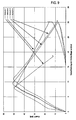
- Figure 9 shows the results of the displacement measurements on the end support.
- the table of Figure 10 shows the compilation of the statistical evaluation of the achieved loads again.
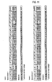
- Figures 11-13 contain the most important dimensions of the tested trapezoidal sheets.
- the slit should be limited to the area of the pockets, as shown in FIG.
- the bearing widths b A of the elements according to the invention in the region of the transverse joint construction according to FIG. 14 correspond to the minimum bearing widths of end supports according to DIN 18807 part 3, paragraph 4.2.1, the entirety of which is hereby incorporated by reference.
- the bottom unslotted or non-notched trapezoidal sheet is usually not attached immediately after installation on the support.
- the overhead slotted or notched trapezoidal sheet has the possibility of immediate attachment after installation.
- DIN 18807 minimum support widths for the trapezoidal sheet according to the invention are shown in the table of Figure 17.
- connection between the slotted or notched trapezoidal sheet and the substructure should be as close to the end of slotting or notching due to the cross-sectional weakening at high Sogbelastept.
Landscapes
- Engineering & Computer Science (AREA)
- Architecture (AREA)
- Civil Engineering (AREA)
- Structural Engineering (AREA)
- Mechanical Engineering (AREA)
- Roof Covering Using Slabs Or Stiff Sheets (AREA)
- Finishing Walls (AREA)
- Transition And Organic Metals Composition Catalysts For Addition Polymerization (AREA)
Claims (6)
- Jointure bout-à-bout entre deux éléments de tôles de toiture (1,2) dans les parois profilées (6.7) desquels des contre-dépouilles, des gorges ou des ergots moulés et en saillie sont ménagés - les éléments de tôles de toiture à assembler bout-à-bout possédant, pour la même dimension de profil, la même section transversale. Cette jointure est caractérisée par le fait que les éléments de tôles de toiture (1.2) se chevauchent dans la zone d'assemblage, les contre-dépouilles, gorges ou ergots (8.9) d'au moins un des éléments de tôles de toiture (1) étant au moins en partie retirés ou évidés des deux côtés dans la zone d'assemblage afin de former des encoches (11) ou une entaille (15) qui découpent dans une très large mesure les contre-dépouilles, gorges ou ergots (8.9) et qui s'étendent de l'arête faciale (12), dans le sens longitudinal de l'élément de tôle de toiture (1) parallèlement au sommet de la tôle, sur toute la longueur de l'assemblage.
- Jointure bout-à-bout selon la revendication 1, caractérisée par le fait que les éléments de tôles de toiture (1,2) sont, au moins au niveau de leurs membrures inférieures (13,14), posées à plat l'une sur l'autre.
- Jointure bout-à-bout selon au moins l'une des revendications qui précèdent, caractérisée par le fait que les contre-dépouilles, gorges ou ergots (8,9) sont au moins en partie retirés par des encoches pratiquées à leur niveau des deux côtés (11).
- Jointure bout-à-bout selon au moins l'une des revendications qui précèdent, caractérisée par le fait que les contre-dépouilles, gorges ou ergots (8,9) sont au moins en partie retirés par une entaille de profil (15).
- Jeu de deux éléments de tôles de toiture (1,2) pour une jointure bout-à-bout selon la revendication 1, en particulier avec une section transversale pratiquement trapézoïdale - des contre-dépouilles, gorges ou ergots (8,9) étant moulés dans ses parois latérales (6,7) et en saillie et les éléments de tôles de toiture à assembler bout-à-bout (1.2) possédant pour la même dimension de profil la même section transversale - caractérisé par le fait qu'au moins l'un des éléments de tôles de toiture (1.2) possède des deux côtés, dans la zone des contre-dépouilles, gorges ou ergots (8.9) des encoches (11) ou une entaille (15) qui découpent dans une très large mesure les contre-dépouilles, gorges ou ergots (8.9) et qui s'étendent de l'arête faciale (12), dans le sens longitudinal de l'élément de tôle de couverture (1) parallèlement au sommet de la tôle, sur la longueur prévue de l'assemblage.
- Jeu de deux éléments de tôles de toiture (1,2) selon la revendication 5, caractérisé par le fait qu'un élément de tôle de toiture (1) est entaillé dans une large mesure, y compris le sommet de la tôle, dans la zone des contre-dépouilles, gorges ou ergots (8.9) et que les contre-dépouilles, gorges ou ergots (8,9) sont découpés dans une large mesure et que l'entaille (15) s'étend de l'arête faciale (12) dans le sens longitudinal de l'élément de tôle de toiture (1) parallèlement au sommet initial de la tôle.
Applications Claiming Priority (3)
| Application Number | Priority Date | Filing Date | Title |
|---|---|---|---|
| DE20118696U | 2001-11-19 | ||
| DE20118696U DE20118696U1 (de) | 2001-11-19 | 2001-11-19 | Stirnseitige Stoßverbindung zwischen zwei Dachblechelementen eines Flachdachs und hierzu geeignetes Dachblechelement |
| PCT/DE2002/004209 WO2003046305A1 (fr) | 2001-11-19 | 2002-11-14 | Jointure faciale entre deux elements de tole de toiture pour un toit plat et element de tole de toiture concu a cette fin |
Publications (2)
| Publication Number | Publication Date |
|---|---|
| EP1446541A1 EP1446541A1 (fr) | 2004-08-18 |
| EP1446541B1 true EP1446541B1 (fr) | 2007-10-17 |
Family
ID=7964084
Family Applications (1)
| Application Number | Title | Priority Date | Filing Date |
|---|---|---|---|
| EP02803745A Expired - Lifetime EP1446541B1 (fr) | 2001-11-19 | 2002-11-14 | Jointure faciale entre deux elements de tole de toiture pour un toit plat et element de tole de toiture concu a cette fin |
Country Status (6)
| Country | Link |
|---|---|
| US (1) | US20050022464A1 (fr) |
| EP (1) | EP1446541B1 (fr) |
| AT (1) | ATE376107T1 (fr) |
| AU (1) | AU2002365458A1 (fr) |
| DE (5) | DE20118696U1 (fr) |
| WO (1) | WO2003046305A1 (fr) |
Families Citing this family (1)
| Publication number | Priority date | Publication date | Assignee | Title |
|---|---|---|---|---|
| DE102005055891B4 (de) * | 2004-11-23 | 2009-08-06 | Harald Zahn Gmbh | Befestigung von Dämm- und Dichtungsmaterialien auf einem Stahltrapezprofilblech mittels Klemmlaschen |
Family Cites Families (8)
| Publication number | Priority date | Publication date | Assignee | Title |
|---|---|---|---|---|
| US466850A (en) * | 1892-01-12 | Metallic standing-seam roofing | ||
| US1706924A (en) * | 1926-06-12 | 1929-03-26 | Truscon Steel Co | Metal roof-deck construction |
| FR1176824A (fr) * | 1957-06-20 | 1959-04-16 | Wendel Et Cie De | Panneau perfectionné, notamment pour toitures |
| FR1491552A (fr) | 1966-07-01 | 1967-08-11 | Profil Sa Ind Financ Le | Perfectionnements apportés aux panneaux nervurés et à leurs applications |
| US3760545A (en) * | 1971-06-07 | 1973-09-25 | Rooftilers Pty Ltd | Tiling of roofs |
| US5737894A (en) * | 1984-01-04 | 1998-04-14 | Harold Simpson, Inc. | Standing seam assembly |
| JPH0627420B2 (ja) * | 1985-04-12 | 1994-04-13 | 三晃金属工業株式会社 | 屋根継手構造 |
| DE19943661B4 (de) | 1999-09-13 | 2004-10-21 | Harald Zahn Gmbh | Befestigungssystem für das Aufbringen von Dämmmaterial und Dichtungsbahnen |
-
2001
- 2001-11-19 DE DE20118696U patent/DE20118696U1/de not_active Expired - Lifetime
-
2002
- 2002-11-14 US US10/496,156 patent/US20050022464A1/en not_active Abandoned
- 2002-11-14 DE DE50211091T patent/DE50211091D1/de not_active Expired - Lifetime
- 2002-11-14 WO PCT/DE2002/004209 patent/WO2003046305A1/fr not_active Ceased
- 2002-11-14 DE DE10295523T patent/DE10295523D2/de not_active Expired - Fee Related
- 2002-11-14 AT AT02803745T patent/ATE376107T1/de active
- 2002-11-14 EP EP02803745A patent/EP1446541B1/fr not_active Expired - Lifetime
- 2002-11-14 AU AU2002365458A patent/AU2002365458A1/en not_active Abandoned
- 2002-11-18 DE DE20217862U patent/DE20217862U1/de not_active Expired - Lifetime
- 2002-11-18 DE DE10253826A patent/DE10253826A1/de not_active Withdrawn
Also Published As
| Publication number | Publication date |
|---|---|
| WO2003046305A1 (fr) | 2003-06-05 |
| DE20118696U1 (de) | 2002-02-14 |
| DE10295523D2 (en) | 2004-10-07 |
| EP1446541A1 (fr) | 2004-08-18 |
| AU2002365458A1 (en) | 2003-06-10 |
| US20050022464A1 (en) | 2005-02-03 |
| DE50211091D1 (de) | 2007-11-29 |
| ATE376107T1 (de) | 2007-11-15 |
| DE10253826A1 (de) | 2003-05-28 |
| DE20217862U1 (de) | 2003-04-10 |
Similar Documents
| Publication | Publication Date | Title |
|---|---|---|
| EP1238222B1 (fr) | Rail de montage forme d'au moins un element profile | |
| DE60309809T2 (de) | Verbindungselement für Holzträger | |
| DE3736553A1 (de) | Wandverbindungsteil | |
| EP0773324B1 (fr) | Dispositif pour la connection et la transmission des forces transversales entre deux structures séparées par un joint | |
| EP2084340B1 (fr) | Revêtement, habillage ou analogue pour bâtiments ou parties de bâtiments | |
| DE3879497T2 (de) | Metallstuetze. | |
| DE202018003027U1 (de) | Verbindungsstück zur winkeligen Verbindung zweier Bauteile | |
| EP1446541B1 (fr) | Jointure faciale entre deux elements de tole de toiture pour un toit plat et element de tole de toiture concu a cette fin | |
| DE102019002620A1 (de) | Verbindungssystem für Holz- und/oder Metallkonstruktionen | |
| DE202012104226U1 (de) | Vorrichtung zur Befestigung von plattenförmigen Elementen an Trägerflanschen | |
| EP0641905A1 (fr) | Panneau de coffrage lié au ciment, comportant une ligne de pliage | |
| EP2516761B1 (fr) | Dispositif permettant de raccorder deux éléments de construction séparés par un joint et d'absorber des efforts de cisaillement apparaissant entre les éléments de construction | |
| DE102014215814A1 (de) | Spannschloss, Box, Bauelement und Bausatz | |
| EP1793057A2 (fr) | Profilé d'extension pour augmenter la hauteur d'un support | |
| DE202018103083U1 (de) | Befestigungssystem mit Kraftverteilung | |
| DE102020127816A1 (de) | Verkleidungssystem für eine Wand und Anordnung des Verkleidungssystems an einer Wand | |
| DE102004022276B4 (de) | Vorrichtung zur Befestigung von Dämmstoffelementen an ebenen Flächen | |
| EP2354362B1 (fr) | Dispositif de fixation pour l'ancrage d'éléments de construction sur un toit plat | |
| EP0397293B1 (fr) | Rail de fixation pour tôles à ondes trapézoidales pour la technique de la construction | |
| DE2559459C3 (de) | In Betonkonstruktionen bündig einbettbarer Schwerlastanker | |
| DE3836483A1 (de) | Biegesteife eckverbindung eines holzbalkens mit einer stuetze | |
| EP4253686A1 (fr) | Façade de bâtiment pourvue de système d'ancrage | |
| DE202020001489U1 (de) | Verbindungselement für den Anschluss zweier Holzbauteile | |
| DE202022105479U1 (de) | Bodenstütze eines Kabeltragsystems | |
| DE2523827A1 (de) | Kabelschacht |
Legal Events
| Date | Code | Title | Description |
|---|---|---|---|
| PUAI | Public reference made under article 153(3) epc to a published international application that has entered the european phase |
Free format text: ORIGINAL CODE: 0009012 |
|
| 17P | Request for examination filed |
Effective date: 20040402 |
|
| AK | Designated contracting states |
Kind code of ref document: A1 Designated state(s): AT BE BG CH CY CZ DE DK EE ES FI FR GB GR IE IT LI LU MC NL PT SE SK TR |
|
| AX | Request for extension of the european patent |
Extension state: AL LT LV MK RO SI |
|
| 17Q | First examination report despatched |
Effective date: 20061221 |
|
| GRAP | Despatch of communication of intention to grant a patent |
Free format text: ORIGINAL CODE: EPIDOSNIGR1 |
|
| GRAS | Grant fee paid |
Free format text: ORIGINAL CODE: EPIDOSNIGR3 |
|
| GRAA | (expected) grant |
Free format text: ORIGINAL CODE: 0009210 |
|
| AK | Designated contracting states |
Kind code of ref document: B1 Designated state(s): AT BE BG CH CY CZ DE DK EE ES FI FR GB GR IE IT LI LU MC NL PT SE SK TR |
|
| REG | Reference to a national code |
Ref country code: GB Ref legal event code: FG4D Free format text: NOT ENGLISH |
|
| REG | Reference to a national code |
Ref country code: CH Ref legal event code: NV Representative=s name: FELBER & PARTNER AG PATENTANWAELTE Ref country code: CH Ref legal event code: EP |
|
| REG | Reference to a national code |
Ref country code: IE Ref legal event code: FG4D Free format text: LANGUAGE OF EP DOCUMENT: GERMAN |
|
| REF | Corresponds to: |
Ref document number: 50211091 Country of ref document: DE Date of ref document: 20071129 Kind code of ref document: P |
|
| NLV1 | Nl: lapsed or annulled due to failure to fulfill the requirements of art. 29p and 29m of the patents act | ||
| PG25 | Lapsed in a contracting state [announced via postgrant information from national office to epo] |
Ref country code: SE Free format text: LAPSE BECAUSE OF FAILURE TO SUBMIT A TRANSLATION OF THE DESCRIPTION OR TO PAY THE FEE WITHIN THE PRESCRIBED TIME-LIMIT Effective date: 20080117 Ref country code: NL Free format text: LAPSE BECAUSE OF FAILURE TO SUBMIT A TRANSLATION OF THE DESCRIPTION OR TO PAY THE FEE WITHIN THE PRESCRIBED TIME-LIMIT Effective date: 20071017 Ref country code: ES Free format text: LAPSE BECAUSE OF FAILURE TO SUBMIT A TRANSLATION OF THE DESCRIPTION OR TO PAY THE FEE WITHIN THE PRESCRIBED TIME-LIMIT Effective date: 20080128 |
|
| GBV | Gb: ep patent (uk) treated as always having been void in accordance with gb section 77(7)/1977 [no translation filed] | ||
| PG25 | Lapsed in a contracting state [announced via postgrant information from national office to epo] |
Ref country code: PT Free format text: LAPSE BECAUSE OF FAILURE TO SUBMIT A TRANSLATION OF THE DESCRIPTION OR TO PAY THE FEE WITHIN THE PRESCRIBED TIME-LIMIT Effective date: 20080317 Ref country code: BG Free format text: LAPSE BECAUSE OF FAILURE TO SUBMIT A TRANSLATION OF THE DESCRIPTION OR TO PAY THE FEE WITHIN THE PRESCRIBED TIME-LIMIT Effective date: 20080117 |
|
| BERE | Be: lapsed |
Owner name: HARALD ZAHN G.M.B.H. Effective date: 20071130 |
|
| REG | Reference to a national code |
Ref country code: IE Ref legal event code: FD4D |
|
| PG25 | Lapsed in a contracting state [announced via postgrant information from national office to epo] |
Ref country code: MC Free format text: LAPSE BECAUSE OF NON-PAYMENT OF DUE FEES Effective date: 20071130 |
|
| PG25 | Lapsed in a contracting state [announced via postgrant information from national office to epo] |
Ref country code: CZ Free format text: LAPSE BECAUSE OF FAILURE TO SUBMIT A TRANSLATION OF THE DESCRIPTION OR TO PAY THE FEE WITHIN THE PRESCRIBED TIME-LIMIT Effective date: 20071017 Ref country code: DK Free format text: LAPSE BECAUSE OF FAILURE TO SUBMIT A TRANSLATION OF THE DESCRIPTION OR TO PAY THE FEE WITHIN THE PRESCRIBED TIME-LIMIT Effective date: 20071017 |
|
| EN | Fr: translation not filed | ||
| PLBE | No opposition filed within time limit |
Free format text: ORIGINAL CODE: 0009261 |
|
| STAA | Information on the status of an ep patent application or granted ep patent |
Free format text: STATUS: NO OPPOSITION FILED WITHIN TIME LIMIT |
|
| PG25 | Lapsed in a contracting state [announced via postgrant information from national office to epo] |
Ref country code: SK Free format text: LAPSE BECAUSE OF FAILURE TO SUBMIT A TRANSLATION OF THE DESCRIPTION OR TO PAY THE FEE WITHIN THE PRESCRIBED TIME-LIMIT Effective date: 20071017 |
|
| 26N | No opposition filed |
Effective date: 20080718 |
|
| PG25 | Lapsed in a contracting state [announced via postgrant information from national office to epo] |
Ref country code: BE Free format text: LAPSE BECAUSE OF NON-PAYMENT OF DUE FEES Effective date: 20071130 |
|
| PG25 | Lapsed in a contracting state [announced via postgrant information from national office to epo] |
Ref country code: FR Free format text: LAPSE BECAUSE OF FAILURE TO SUBMIT A TRANSLATION OF THE DESCRIPTION OR TO PAY THE FEE WITHIN THE PRESCRIBED TIME-LIMIT Effective date: 20080801 Ref country code: IE Free format text: LAPSE BECAUSE OF FAILURE TO SUBMIT A TRANSLATION OF THE DESCRIPTION OR TO PAY THE FEE WITHIN THE PRESCRIBED TIME-LIMIT Effective date: 20071017 |
|
| PG25 | Lapsed in a contracting state [announced via postgrant information from national office to epo] |
Ref country code: GB Free format text: LAPSE BECAUSE OF FAILURE TO SUBMIT A TRANSLATION OF THE DESCRIPTION OR TO PAY THE FEE WITHIN THE PRESCRIBED TIME-LIMIT Effective date: 20071017 |
|
| PG25 | Lapsed in a contracting state [announced via postgrant information from national office to epo] |
Ref country code: EE Free format text: LAPSE BECAUSE OF FAILURE TO SUBMIT A TRANSLATION OF THE DESCRIPTION OR TO PAY THE FEE WITHIN THE PRESCRIBED TIME-LIMIT Effective date: 20071017 Ref country code: GR Free format text: LAPSE BECAUSE OF FAILURE TO SUBMIT A TRANSLATION OF THE DESCRIPTION OR TO PAY THE FEE WITHIN THE PRESCRIBED TIME-LIMIT Effective date: 20080118 |
|
| PG25 | Lapsed in a contracting state [announced via postgrant information from national office to epo] |
Ref country code: FI Free format text: LAPSE BECAUSE OF FAILURE TO SUBMIT A TRANSLATION OF THE DESCRIPTION OR TO PAY THE FEE WITHIN THE PRESCRIBED TIME-LIMIT Effective date: 20071017 |
|
| PG25 | Lapsed in a contracting state [announced via postgrant information from national office to epo] |
Ref country code: CY Free format text: LAPSE BECAUSE OF FAILURE TO SUBMIT A TRANSLATION OF THE DESCRIPTION OR TO PAY THE FEE WITHIN THE PRESCRIBED TIME-LIMIT Effective date: 20071017 |
|
| PG25 | Lapsed in a contracting state [announced via postgrant information from national office to epo] |
Ref country code: LU Free format text: LAPSE BECAUSE OF NON-PAYMENT OF DUE FEES Effective date: 20071114 |
|
| PG25 | Lapsed in a contracting state [announced via postgrant information from national office to epo] |
Ref country code: TR Free format text: LAPSE BECAUSE OF FAILURE TO SUBMIT A TRANSLATION OF THE DESCRIPTION OR TO PAY THE FEE WITHIN THE PRESCRIBED TIME-LIMIT Effective date: 20071017 |
|
| PGFP | Annual fee paid to national office [announced via postgrant information from national office to epo] |
Ref country code: AT Payment date: 20100907 Year of fee payment: 9 |
|
| PG25 | Lapsed in a contracting state [announced via postgrant information from national office to epo] |
Ref country code: IT Free format text: LAPSE BECAUSE OF NON-PAYMENT OF DUE FEES Effective date: 20071130 |
|
| PGFP | Annual fee paid to national office [announced via postgrant information from national office to epo] |
Ref country code: CH Payment date: 20101004 Year of fee payment: 9 |
|
| REG | Reference to a national code |
Ref country code: CH Ref legal event code: PL |
|
| PG25 | Lapsed in a contracting state [announced via postgrant information from national office to epo] |
Ref country code: LI Free format text: LAPSE BECAUSE OF NON-PAYMENT OF DUE FEES Effective date: 20111130 Ref country code: CH Free format text: LAPSE BECAUSE OF NON-PAYMENT OF DUE FEES Effective date: 20111130 |
|
| REG | Reference to a national code |
Ref country code: AT Ref legal event code: MM01 Ref document number: 376107 Country of ref document: AT Kind code of ref document: T Effective date: 20111114 |
|
| PG25 | Lapsed in a contracting state [announced via postgrant information from national office to epo] |
Ref country code: AT Free format text: LAPSE BECAUSE OF NON-PAYMENT OF DUE FEES Effective date: 20111114 |
|
| REG | Reference to a national code |
Ref country code: DE Ref legal event code: R082 Ref document number: 50211091 Country of ref document: DE Representative=s name: REBLE & KESSELHUT PARTNERSCHAFTSGESELLSCHAFT V, DE |
|
| PGFP | Annual fee paid to national office [announced via postgrant information from national office to epo] |
Ref country code: DE Payment date: 20211122 Year of fee payment: 20 |
|
| REG | Reference to a national code |
Ref country code: DE Ref legal event code: R071 Ref document number: 50211091 Country of ref document: DE |