EP1446571B1 - Soupape d'injection de carburant pour des moteurs a combustion interne - Google Patents
Soupape d'injection de carburant pour des moteurs a combustion interne Download PDFInfo
- Publication number
- EP1446571B1 EP1446571B1 EP02767066A EP02767066A EP1446571B1 EP 1446571 B1 EP1446571 B1 EP 1446571B1 EP 02767066 A EP02767066 A EP 02767066A EP 02767066 A EP02767066 A EP 02767066A EP 1446571 B1 EP1446571 B1 EP 1446571B1
- Authority
- EP
- European Patent Office
- Prior art keywords
- valve needle
- valve
- external
- internal
- sealing edge
- Prior art date
- Legal status (The legal status is an assumption and is not a legal conclusion. Google has not performed a legal analysis and makes no representation as to the accuracy of the status listed.)
- Expired - Lifetime
Links
- 238000002347 injection Methods 0.000 title claims abstract description 73
- 239000007924 injection Substances 0.000 title claims abstract description 73
- 239000000446 fuel Substances 0.000 title claims abstract description 40
- 238000002485 combustion reaction Methods 0.000 title claims abstract description 28
- 238000007789 sealing Methods 0.000 claims abstract description 89
- 230000000694 effects Effects 0.000 claims description 7
- 238000011144 upstream manufacturing Methods 0.000 claims description 5
- 230000005489 elastic deformation Effects 0.000 claims description 4
- 239000000567 combustion gas Substances 0.000 description 4
- 239000004215 Carbon black (E152) Substances 0.000 description 2
- 239000011324 bead Substances 0.000 description 2
- 229930195733 hydrocarbon Natural products 0.000 description 2
- 150000002430 hydrocarbons Chemical class 0.000 description 2
- 230000002787 reinforcement Effects 0.000 description 2
- 238000007664 blowing Methods 0.000 description 1
- 238000010276 construction Methods 0.000 description 1
- 239000007789 gas Substances 0.000 description 1
- 238000009434 installation Methods 0.000 description 1
- 238000004519 manufacturing process Methods 0.000 description 1
- 230000035515 penetration Effects 0.000 description 1
- 230000007704 transition Effects 0.000 description 1
Images
Classifications
-
- F—MECHANICAL ENGINEERING; LIGHTING; HEATING; WEAPONS; BLASTING
- F02—COMBUSTION ENGINES; HOT-GAS OR COMBUSTION-PRODUCT ENGINE PLANTS
- F02M—SUPPLYING COMBUSTION ENGINES IN GENERAL WITH COMBUSTIBLE MIXTURES OR CONSTITUENTS THEREOF
- F02M61/00—Fuel-injectors not provided for in groups F02M39/00 - F02M57/00 or F02M67/00
- F02M61/16—Details not provided for in, or of interest apart from, the apparatus of groups F02M61/02 - F02M61/14
- F02M61/18—Injection nozzles, e.g. having valve seats; Details of valve member seated ends, not otherwise provided for
- F02M61/1866—Valve seats or member ends having multiple cones
-
- F—MECHANICAL ENGINEERING; LIGHTING; HEATING; WEAPONS; BLASTING
- F02—COMBUSTION ENGINES; HOT-GAS OR COMBUSTION-PRODUCT ENGINE PLANTS
- F02M—SUPPLYING COMBUSTION ENGINES IN GENERAL WITH COMBUSTIBLE MIXTURES OR CONSTITUENTS THEREOF
- F02M45/00—Fuel-injection apparatus characterised by having a cyclic delivery of specific time/pressure or time/quantity relationship
- F02M45/02—Fuel-injection apparatus characterised by having a cyclic delivery of specific time/pressure or time/quantity relationship with each cyclic delivery being separated into two or more parts
- F02M45/04—Fuel-injection apparatus characterised by having a cyclic delivery of specific time/pressure or time/quantity relationship with each cyclic delivery being separated into two or more parts with a small initial part, e.g. initial part for partial load and initial and main part for full load
- F02M45/08—Injectors peculiar thereto
- F02M45/086—Having more than one injection-valve controlling discharge orifices
-
- F—MECHANICAL ENGINEERING; LIGHTING; HEATING; WEAPONS; BLASTING
- F02—COMBUSTION ENGINES; HOT-GAS OR COMBUSTION-PRODUCT ENGINE PLANTS
- F02M—SUPPLYING COMBUSTION ENGINES IN GENERAL WITH COMBUSTIBLE MIXTURES OR CONSTITUENTS THEREOF
- F02M61/00—Fuel-injectors not provided for in groups F02M39/00 - F02M57/00 or F02M67/00
- F02M61/16—Details not provided for in, or of interest apart from, the apparatus of groups F02M61/02 - F02M61/14
- F02M61/18—Injection nozzles, e.g. having valve seats; Details of valve member seated ends, not otherwise provided for
-
- F—MECHANICAL ENGINEERING; LIGHTING; HEATING; WEAPONS; BLASTING
- F02—COMBUSTION ENGINES; HOT-GAS OR COMBUSTION-PRODUCT ENGINE PLANTS
- F02M—SUPPLYING COMBUSTION ENGINES IN GENERAL WITH COMBUSTIBLE MIXTURES OR CONSTITUENTS THEREOF
- F02M61/00—Fuel-injectors not provided for in groups F02M39/00 - F02M57/00 or F02M67/00
- F02M61/16—Details not provided for in, or of interest apart from, the apparatus of groups F02M61/02 - F02M61/14
- F02M61/18—Injection nozzles, e.g. having valve seats; Details of valve member seated ends, not otherwise provided for
- F02M61/1806—Injection nozzles, e.g. having valve seats; Details of valve member seated ends, not otherwise provided for characterised by the arrangement of discharge orifices, e.g. orientation or size
- F02M61/182—Discharge orifices being situated in different transversal planes with respect to valve member direction of movement
-
- F—MECHANICAL ENGINEERING; LIGHTING; HEATING; WEAPONS; BLASTING
- F02—COMBUSTION ENGINES; HOT-GAS OR COMBUSTION-PRODUCT ENGINE PLANTS
- F02M—SUPPLYING COMBUSTION ENGINES IN GENERAL WITH COMBUSTIBLE MIXTURES OR CONSTITUENTS THEREOF
- F02M61/00—Fuel-injectors not provided for in groups F02M39/00 - F02M57/00 or F02M67/00
- F02M61/16—Details not provided for in, or of interest apart from, the apparatus of groups F02M61/02 - F02M61/14
- F02M61/18—Injection nozzles, e.g. having valve seats; Details of valve member seated ends, not otherwise provided for
- F02M61/1873—Valve seats or member ends having circumferential grooves or ridges, e.g. toroidal
-
- F—MECHANICAL ENGINEERING; LIGHTING; HEATING; WEAPONS; BLASTING
- F02—COMBUSTION ENGINES; HOT-GAS OR COMBUSTION-PRODUCT ENGINE PLANTS
- F02M—SUPPLYING COMBUSTION ENGINES IN GENERAL WITH COMBUSTIBLE MIXTURES OR CONSTITUENTS THEREOF
- F02M2200/00—Details of fuel-injection apparatus, not otherwise provided for
- F02M2200/46—Valves, e.g. injectors, with concentric valve bodies
Definitions
- the invention is based on a fuel injection valve for Internal combustion engine, as it is the type of claim 1 corresponds.
- a fuel injection valve is for example from the published patent application DE 30 36 583 A1 known. That known from the prior art Fuel injection valve has a valve body with a formed therein bore. In the hole is an outer one Valve needle out and turn in the outer valve needle an inner valve needle. Both valve needles work with a valve seat together, the bore on the combustion chamber side End closes. In the valve seat are an outer and formed an inner injection opening row, wherein the Inner injection port row from the inner valve needle and the outer injection port row from the outer valve needle -controlled.
- a longitudinal movement of the valve pins in the bore against a closing force either turned on only the outer injection opening row or both injection port rows simultaneously, so that Fuel can flow to the injection ports, from where he is injected into the combustion chamber of the internal combustion engine.
- Both the outer valve needle and the inner valve needle have on their valve sealing surfaces, with which they on Abut valve seat, each having a sealing edge, the one Sealing of the pressure chamber against the respective injection opening row ensures.
- this results in the Disadvantage that the injection valve during the closed Phase in which no fuel through the injection openings should escape, the two Einspritzötechnischsschn not sufficiently sealed against each other.
- This can on the one hand Combustion gases from the combustion chamber as so-called back-blowing in the space between the two valve pins is present, penetrate.
- fuel the is also located between the valve pins during operation, as leakage into the combustion chamber flow and there to one Increase in hydrocarbon emissions.
- the fuel injection valve according to the invention with the characterizing Features of claim 1 has in contrast the advantage that no leakage and thus no leakage of Fuel between the injections is possible and that from the combustion chamber of the internal combustion engine no combustion gases through the injection openings in the fuel injection valve can penetrate.
- the outer valve needle an inwardly cantilevered sealing lip, the one having inner sealing edge. This inner sealing edge comes in Closed position of the outer valve needle on the valve seat for Plant and seals so the outer injection hole row against the inner injection port row.
- annular space formed with fuel can be filled under high pressure.
- the fuel in the annulus acts on the formed on the inner valve needle Pressure surface, so that a directed away from the valve seat force is exerted on the inner valve needle.
- the inner valve needle can hydraulically in a simple manner be controlled, with the annulus with little effort can be realized.
- the outer Valve needle formed substantially hollow cylindrical, and the pressure chamber is through a groove in the inner circumferential surface formed the outer valve needle.
- the Sealing lip on a seat facing away from the valve, on the the inner valve needle with a sealing surface in the closed position comes to the plant. This will cause the inner sealing edge, which is formed on the sealing lip, by the closing force the inner valve needle additionally against the valve seat pressed, so that the sealing effect of the inner sealing edge is significantly improved.
- the outer Valve needle next to the inner sealing edge an additional outer sealing edge, which upstream to the inner Sealing edge and also upstream to the outer injection port row is arranged.
- the seal inner and outer sealing edge the outer injection port row completely, so no fuel through the outer injection opening row uncontrolled into the combustion chamber can get. There can be no other way around Combustion gases from the combustion chamber into the fuel injection valve penetration.
- the sealing lip designed so that during the closing movement of the outer Valve needle first the inner sealing edge on the valve seat to Plant comes and only with the further closing movement under elastic deformation of the sealing lip and the outer sealing edge. Due to the elastic deformation of the sealing lip is the contact pressure on the inner sealing edge increases, so that in the case where only the inner valve needle from the valve seat lifts and thereby the inner injection port row releases, still a secure seal on the inner Sealing edge of the outer valve needle is given.
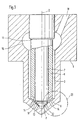
- a fuel injection valve in longitudinal section shown in Figure 1, a fuel injection valve in longitudinal section shown.
- a valve body 1 a bore 3 is formed, wherein the bore 3 is closed by a valve seat 10 is, which is formed substantially conical.
- this valve seat 10 is on the combustion chamber side End of the bore 3 is arranged.
- an outer Valve needle 5 is arranged, which is longitudinally displaceable there is and in a brennraumabgewandten section of the bore 3 is guided.
- the outer valve needle 5 is a piston-shaped inner valve needle 7 guided longitudinally displaceable, the a longitudinal axis 2, which with the longitudinal axis of outer valve needle 5 coincides.
- the outer valve needle 5 has at its the valve seat 10 end facing a in essential conical valve sealing surface 6, which in Closed position of the outer valve needle 5 on the valve seat 10th comes to the plant.
- the inner valve needle 7 also has one essentially conical sealing surface 8, which in the closed position also comes to the valve seat 10 to the plant.
- a Pressure shoulder 11 formed between the outer valve needle 5 and the wall of the bore 3, a pressure chamber 16 is formed, the via a formed in the valve body 1 inlet channel 18 can be filled with fuel under high pressure.
- the pressure chamber 16 is radial extended, so that the inlet channel 18 in the valve body.
- valve 1 can train without the leadership of the outer valve needle. 5 in the hole 3 by a too small wall thickness between to weaken the bore 3 and the inlet channel 18.
- a longitudinal movement of Valve needles 5, 7 in the bore 3 takes place thereby, that either the opening force on the outer valve needle 5, by the hydraulic force on the pressure shoulder 11th is generated by the increasing pressure in the pressure chamber 16th exceeds the closing force or that at least one approximately constant fuel pressure in the pressure chamber 16 reduces the closing force on the outer valve needle 5 becomes.
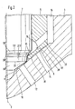
- FIG. 2 shows an enlargement of the designated II section of Figure 1.
- the valve seat 10 In the valve seat 10 are a plurality of injection openings formed, the valve seat 10 with the Combust combustion chamber of the internal combustion engine.
- the injection openings are arranged in two rows of injection openings 12, 14, wherein the inner injection opening row 12 closer the longitudinal axis 2 is located as the outer injection opening row 14.
- the inner valve needle 7 has at its combustion chamber facing End a sequence of a cone surface 107, one adjoining first cylindrical surface 117, one following second cone surface 207, a subsequent second cylindrical surface 217 and an adjacent thereto third cone surface 307 on.
- the opening angle of the third Cone surface 307 is larger than the opening angle of the conical Valve seat 10, so that at the transition of the second cylindrical surface 217 to the third cone surface 307 a sealing edge 27 is formed, in the closed position of the inner valve needle 7 comes to the valve seat 10 to the plant.
- the sealing edge 27 comes here upstream of the inner row of injection openings 12 at the valve seat 10 to the plant, so that the sealing edge 27 can close the inner injection opening 12 series.
- the outer valve needle 5 has near its combustion chamber side End a groove 19 on, so that between the inner Valve needle 7 and the outer valve needle 5, an annular space 20th is formed.
- the annulus 20 is over several over the circumference the outer valve needle 5 distributed connecting bores 22 connected to the pressure chamber 16, and thus prevails in the annular space 20 always the same fuel pressure as in the pressure chamber 16.
- the combustion chamber-side end surface of the outer Valve needle 5 is approximately conical and has an outer ring formed by an annular bead formed thereon Sealing edge 32, which when attached to the valve seat 10 the Pressure chamber 16 against the outer injection opening row 14 closes.
- the inner one Sealing edge 30 and the outer sealing edge 32 are here arranged so that the outer sealing edge 32 upstream and the inner sealing edge 30 downstream of the outer injection opening row 14 are arranged so that at the plant the two sealing edges 30, 32 on the valve seat 10, the outer Injection opening row 14 is sealingly closed.
- the sealing lip 25 is elastically deformable and designed to that in the closing movement of the lifted off the valve seat 10th outer valve needle 5 first, the inner sealing edge 30 comes to the valve seat 10 to the plant and only then by an elastic deformation of the sealing lip 25 and the outer Sealing edge 32.
- the valve seat 10 remote from the side of the sealing lip 25 is formed as a seat 26, which, when the inner Ventilnader7 is in the closed position, at the as Sealing surface serving second cone surface 207 is applied. hereby results in an additional closing force on the Sealing lip 25 and thus on the inner sealing edge 30, what the sealing effect of the inner sealing edge 30 reinforced.
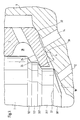
- FIG 3 is an enlargement in the region of the valve seat 10 of Figure 2 shown.
- the reinforcement of the sealing effect on the inner sealing edge 30 of the sealing lip 25 is only then indicated when the sealing lip 25 sufficiently far inward protrudes, leaving them in the closed position of the inner valve needle 7 abuts against the second cone surface 207. Is this Reinforcement of the sealing effect on the inner sealing edge 30 not desired, it may also be provided, the sealing lip 25 to shorten accordingly, so that no more investment takes place on the inner valve needle 7.
- the extension of the Sealing lip 25 by the distance h thus allows the contact force and thus to adjust the sealing effect on the inner sealing edge 30.
- the operation of the fuel injection valve is like follows: Should an injection only through part of the injection openings take place, in this construction example through the inner row of injection ports 12, so does fuel introduced under high pressure in the pressure chamber 16.
- By reducing the closing force on the inner valve needle 7 results from the hydraulic force on the first cone surface 107, which is formed as a pressure surface, an opening force on the inner valve needle 7 from the valve seat 10 away, so that the sealing edge 27 lifts off the valve seat 10 and the annulus 20 with the inner injection port row 12 connects.
- By a correspondingly high closing force on the outer valve needle 5 remain both the inner Sealing edge 30 and the outer sealing edge 32 in abutment on Valve seat 10 and hold so the outer row of injection openings 14 closed.
- the inner valve needle 7 sets its opening movement Continue until you get to one in the drawing shown stop comes to the plant. Shall go through the whole Injection cross section are injected, so will also reduces the closing force on the outer valve needle 5, and the outer valve needle 5 lifts first with the outer one Sealing edge 32 and then with the inner sealing edge 30 from the valve seat 10, so now fuel through both Injection opening rows 12, 14 is injected.
- the Closing of the fuel injection valve takes place in analogue Way by increasing the closing force on the inner Valve needle 7 and the outer valve needle 5, wherein it may be provided, at the same time the pressure in the pressure chamber 16th to reduce.
Landscapes
- Engineering & Computer Science (AREA)
- Chemical & Material Sciences (AREA)
- Combustion & Propulsion (AREA)
- Mechanical Engineering (AREA)
- General Engineering & Computer Science (AREA)
- Fuel-Injection Apparatus (AREA)
Abstract
Claims (7)
- Injecteur de carburant pour un moteur à combustion interne comportant un corps d'injecteur (1) muni d'un perçage (3) recevant une aiguille extérieure (5) avec une aiguille intérieure (7) guidée dans l'aiguille extérieure (5),
au moins l'une des aiguilles d'injecteur (5 ; 7) coopérant avec un siège de soupape (10) réalisé à l'extrémité du perçage (3) du côté de la chambre de combustion, ce siège de soupape comportant une série d'orifices d'éjection extérieurs (14) et une série d'orifices d'éjection intérieurs (12), l'aiguille d'injecteur intérieure (7) commandant l'ouverture de la série des orifices d'éjection intérieurs (12) et l'aiguille d'injecteur extérieure (5) commandant l'ouverture de la série des orifices d'éjection extérieurs (14), alors que des surfaces de pression (11 ; 107) réalisées sur l'aiguille intérieure (7) et sur l'aiguille extérieure (5), sont sollicitées dans le sens de l'ouverture à l'opposé d'une force de fermeture par le carburant fourni,
caractérisé en ce que
l'aiguille d'injecteur extérieure (5) comporte une lèvre d'étanchéité (25) périphérique venant en saillie vers l'intérieur et ayant une arête d'étanchéité (30), intérieure,
cette arête d'étanchéité intérieure (30) venant en appui contre le siège de soupape (10) lorsque l'aiguille extérieure (7) est en position de fermeture. - Injecteur de carburant selon la revendication 1,
caractérisé en ce qu'
une chambre annulaire (20) réalisé entre l'aiguille extérieure (5) et l'aiguille intérieure (7), peut être remplie de carburant à pression élevée. - Injecteur de carburant selon la revendication 2,
caractérisé en ce que
l'aiguille extérieure (5) est essentiellement de forme cylindrique creuse et la chambre annulaire (20) est formé par une gorge réalisée dans la surface-enveloppe intérieure de l'aiguille extérieure (5). - Injecteur de carburant selon la revendication 3,
caractérisé en ce que
la chambre annulaire (20) est reliée par au moins un perçage de liaison (22) réalisé dans l'aiguille extérieure (5) à une chambre de pression (16) qui peut être remplie de carburant à pression élevée. - Injecteur de carburant selon la revendication 1,
caractérisé en ce que
la lèvre d'étanchéité (25) présente une surface de siège (26) à l'opposé du siège de soupape (10) contre laquelle l'aiguille intérieure (7) vient en appui par une surface d'étanchéité (207) en position de fermeture, sous l'action de la force de fermeture. - Injecteur de carburant selon la revendication 1,
caractérisé en ce que
l'aiguille extérieure (5) comporte en plus de l'arête d'étanchéité intérieure (30) également une arête d'étanchéité extérieure (32) en amont de l'arête d'étanchéité intérieure (30) pour que l'arête d'étanchéité extérieure (32) et l'arête d'étanchéité intérieure (30) ferment la série extérieure d'orifices d'éjection (14). - Injecteur de carburant selon la revendication 6,
caractérisé en ce que
lors du mouvement de fermeture de l'aiguille extérieure (5), l'arête d'étanchéité intérieure (30) vient d'abord en appui contre le siège de soupape (10) et ce n'est que lors de la poursuite du mouvement de fermeture et par déformation élastique de la lèvre d'étanchéité (25) que l'arête d'étanchéité extérieure (32) vient également en appui.
Applications Claiming Priority (3)
| Application Number | Priority Date | Filing Date | Title |
|---|---|---|---|
| DE10155227 | 2001-11-09 | ||
| DE10155227A DE10155227A1 (de) | 2001-11-09 | 2001-11-09 | Kraftstoffeinspritzventil für Brennkraftmaschinen |
| PCT/DE2002/002776 WO2003040543A1 (fr) | 2001-11-09 | 2002-07-27 | Soupape d'injection de carburant pour des moteurs a combustion interne |
Publications (2)
| Publication Number | Publication Date |
|---|---|
| EP1446571A1 EP1446571A1 (fr) | 2004-08-18 |
| EP1446571B1 true EP1446571B1 (fr) | 2005-04-06 |
Family
ID=7705287
Family Applications (1)
| Application Number | Title | Priority Date | Filing Date |
|---|---|---|---|
| EP02767066A Expired - Lifetime EP1446571B1 (fr) | 2001-11-09 | 2002-07-27 | Soupape d'injection de carburant pour des moteurs a combustion interne |
Country Status (4)
| Country | Link |
|---|---|
| EP (1) | EP1446571B1 (fr) |
| JP (1) | JP4191606B2 (fr) |
| DE (2) | DE10155227A1 (fr) |
| WO (1) | WO2003040543A1 (fr) |
Cited By (1)
| Publication number | Priority date | Publication date | Assignee | Title |
|---|---|---|---|---|
| WO2018195894A1 (fr) * | 2017-04-28 | 2018-11-01 | 浙江巴腾动力系统有限公司 | Injecteur de carburant pour automobile |
Families Citing this family (26)
| Publication number | Priority date | Publication date | Assignee | Title |
|---|---|---|---|---|
| DE10247958A1 (de) | 2002-10-15 | 2004-04-29 | Robert Bosch Gmbh | Kraftstoff-Einspritzvorrichtung für eine Brennkraftmaschine |
| DE10315821A1 (de) | 2002-11-11 | 2004-05-27 | Robert Bosch Gmbh | Kraftstoffeinspritzventil für Brennkraftmaschinen |
| DE50305296D1 (de) * | 2002-11-11 | 2006-11-16 | Bosch Gmbh Robert | Kraftstoffeinspritzventil für brennkraftmaschinen |
| DE10305303A1 (de) * | 2003-02-10 | 2004-08-19 | Robert Bosch Gmbh | Kraftstoff-Einspritzvorrichtung, insbesondere für Brennkraftmaschinen mit Kraftstoff-Direkteinspritzung |
| DE10306808A1 (de) * | 2003-02-18 | 2004-09-02 | Siemens Ag | Injektor zum Einspritzen von Kraftstoff |
| DE10322826A1 (de) * | 2003-05-19 | 2004-12-09 | Robert Bosch Gmbh | Kraftstoffeinspritzventil für Brennkraftmaschinen |
| US7032566B2 (en) * | 2003-05-30 | 2006-04-25 | Caterpillar Inc. | Fuel injector nozzle for an internal combustion engine |
| DE10351460A1 (de) * | 2003-11-04 | 2005-06-09 | Robert Bosch Gmbh | Kraftstoff-Einspritzvorrichtung, sowie Verfahren zu deren Herstellung |
| DE10354878A1 (de) * | 2003-11-24 | 2005-06-09 | Robert Bosch Gmbh | Kraftstoff-Einspritzvorrichtung, insbesondere für eine Brennkraftmaschine mit Kraftstoff-Direkteinspritzung, sowie Verfahren zu ihrer Herstellung |
| EP1566538B1 (fr) * | 2004-02-20 | 2006-08-09 | Delphi Technologies, Inc. | Buse d'injection |
| DE602005000060T2 (de) | 2004-02-20 | 2007-03-08 | Delphi Technologies, Inc., Troy | Einspritzdüse |
| DE102004011096A1 (de) * | 2004-03-06 | 2005-09-22 | Robert Bosch Gmbh | Kraftstoffeinspritzventil |
| DE102004011095A1 (de) * | 2004-03-06 | 2005-09-22 | Robert Bosch Gmbh | Kraftstoffeinspritzventil |
| DE102004021340A1 (de) * | 2004-04-30 | 2005-11-24 | Siemens Ag | Düsenbaugruppe und Ventil |
| ATE388319T1 (de) * | 2004-08-13 | 2008-03-15 | Delphi Tech Inc | Einspritzdüse |
| DE102004059974A1 (de) * | 2004-11-23 | 2006-06-01 | Siemens Ag | Düsenbaugruppe und Einspritzventil |
| DE102005001675A1 (de) * | 2005-01-13 | 2006-07-27 | Siemens Ag | Düsenbaugruppe und Einspritzventil |
| ATE487048T1 (de) * | 2005-03-04 | 2010-11-15 | Delphi Tech Holding Sarl | Einspritzdüse |
| DE102005037954A1 (de) * | 2005-08-11 | 2007-02-15 | Robert Bosch Gmbh | Kraftstoffeinspritzventil für Brennkraftmaschinen |
| JP4454567B2 (ja) * | 2005-11-14 | 2010-04-21 | 株式会社デンソー | 燃料噴射ノズル |
| DE102006041071A1 (de) * | 2006-09-01 | 2008-03-06 | Robert Bosch Gmbh | Injektor zur Einspritzung von Kraftstoff in Zylinderbrennräume von Brennkraftmaschinen; insbesondere Common-Rail-Injektor |
| DE102012205840A1 (de) * | 2012-04-11 | 2013-10-17 | Continental Automotive Gmbh | Injektor |
| GB201404131D0 (en) * | 2014-03-10 | 2014-04-23 | Delphi Int Operations Lux Srl | Fuel injector |
| DE102014220928A1 (de) | 2014-10-15 | 2016-04-21 | Continental Automotive Gmbh | Registerdüse zum Einspritzen von Kraftstoff in den Brennraum einer Brennkraftmaschine |
| JP2016205197A (ja) | 2015-04-21 | 2016-12-08 | 日立オートモティブシステムズ株式会社 | 燃料噴射装置 |
| US10392987B2 (en) | 2017-03-29 | 2019-08-27 | Cummins Emission Solutions Inc. | Assembly and methods for NOx reducing reagent dosing with variable spray angle nozzle |
Family Cites Families (4)
| Publication number | Priority date | Publication date | Assignee | Title |
|---|---|---|---|---|
| DE3036583A1 (de) * | 1980-09-27 | 1982-05-13 | Robert Bosch Gmbh, 7000 Stuttgart | Kraftstoffeinspritzduese |
| DE3332920A1 (de) * | 1983-09-13 | 1985-03-21 | Klöckner-Humboldt-Deutz AG, 5000 Köln | Kraftstoffeinspritzduese |
| DE4432686C2 (de) * | 1994-09-14 | 1996-09-05 | Man B & W Diesel Ag | Querschnittgesteuerte Einspritzdüse |
| EP1033488B1 (fr) * | 1999-03-04 | 2005-10-19 | Delphi Technologies, Inc. | Injecteur de carburant |
-
2001
- 2001-11-09 DE DE10155227A patent/DE10155227A1/de not_active Withdrawn
-
2002
- 2002-07-27 EP EP02767066A patent/EP1446571B1/fr not_active Expired - Lifetime
- 2002-07-27 DE DE50202740T patent/DE50202740D1/de not_active Expired - Fee Related
- 2002-07-27 JP JP2003542772A patent/JP4191606B2/ja not_active Expired - Fee Related
- 2002-07-27 WO PCT/DE2002/002776 patent/WO2003040543A1/fr not_active Ceased
Cited By (1)
| Publication number | Priority date | Publication date | Assignee | Title |
|---|---|---|---|---|
| WO2018195894A1 (fr) * | 2017-04-28 | 2018-11-01 | 浙江巴腾动力系统有限公司 | Injecteur de carburant pour automobile |
Also Published As
| Publication number | Publication date |
|---|---|
| WO2003040543A1 (fr) | 2003-05-15 |
| JP4191606B2 (ja) | 2008-12-03 |
| EP1446571A1 (fr) | 2004-08-18 |
| DE10155227A1 (de) | 2003-05-22 |
| DE50202740D1 (de) | 2005-05-12 |
| JP2005508474A (ja) | 2005-03-31 |
Similar Documents
| Publication | Publication Date | Title |
|---|---|---|
| EP1446571B1 (fr) | Soupape d'injection de carburant pour des moteurs a combustion interne | |
| DE60038479T2 (de) | Kraftstoffeinspritzventil | |
| EP0943054B1 (fr) | Soupape d'injection de carburant pour moteurs a combustion interne | |
| DE2711350A1 (de) | Kraftstoffeinspritzduese fuer brennkraftmaschinen | |
| DE10315820A1 (de) | Kraftstoffeinspritzventil für Brennkraftmaschinen | |
| DE10246974A1 (de) | Kraftstoffeinspritzvorrichtung für eine Brennkraftmaschine | |
| DE602004004056T2 (de) | Einspritzdüse | |
| DE19843344A1 (de) | Kraftstoffeinspritzventil für Brennkraftmaschinen | |
| EP1373715B1 (fr) | Soupape d'injection de carburant pour moteurs a combustion interne | |
| EP1649160B1 (fr) | Soupape d'injection de carburant pour moteurs a combustion interne | |
| EP1346143B1 (fr) | Soupape d'injection de carburant destinee a des moteurs a combustion interne | |
| EP1627148A1 (fr) | Soupape d'injection de carburant pour moteur a combustion interne | |
| EP1518049B1 (fr) | Soupape d'injection de carburant pour moteurs a combustion interne | |
| DE102017212459A1 (de) | Injektor zur Einspritzung von flüssigem und gasförmigem Kraftstoff | |
| DE10322826A1 (de) | Kraftstoffeinspritzventil für Brennkraftmaschinen | |
| DE19954288A1 (de) | Kraftstoffeinspritzventil für Brennkraftmaschinen | |
| EP1608866B1 (fr) | Soupape d'injection de carburant de moteurs a combustion interne | |
| DE2434339A1 (de) | Fluessigkraftstoff-einspritzduese | |
| EP1840366B1 (fr) | Injecteur de carburant | |
| DE19642440A1 (de) | Kraftstoffeinspritzventil für Brennkraftmaschinen | |
| DE10259169A1 (de) | Kraftstoffeinspritzventil für Brennkraftmaschine | |
| DE102016015038B4 (de) | Kraftstoffinjektor | |
| DE10004702A1 (de) | Kraftstoffeinspritzventil für Brennkraftmaschinen | |
| DE10121340A1 (de) | Common-Rail-Injektor | |
| DE10219608A1 (de) | Kraftstoffeinspritzventil für Brennkraftmaschinen |
Legal Events
| Date | Code | Title | Description |
|---|---|---|---|
| PUAI | Public reference made under article 153(3) epc to a published international application that has entered the european phase |
Free format text: ORIGINAL CODE: 0009012 |
|
| 17P | Request for examination filed |
Effective date: 20040609 |
|
| AK | Designated contracting states |
Kind code of ref document: A1 Designated state(s): AT BE BG CH CY CZ DE DK EE ES FI FR GB GR IE IT LI LU MC NL PT SE SK TR |
|
| GRAP | Despatch of communication of intention to grant a patent |
Free format text: ORIGINAL CODE: EPIDOSNIGR1 |
|
| GRAS | Grant fee paid |
Free format text: ORIGINAL CODE: EPIDOSNIGR3 |
|
| GRAA | (expected) grant |
Free format text: ORIGINAL CODE: 0009210 |
|
| AK | Designated contracting states |
Kind code of ref document: B1 Designated state(s): DE FR SE SK TR |
|
| PG25 | Lapsed in a contracting state [announced via postgrant information from national office to epo] |
Ref country code: TR Free format text: LAPSE BECAUSE OF FAILURE TO SUBMIT A TRANSLATION OF THE DESCRIPTION OR TO PAY THE FEE WITHIN THE PRESCRIBED TIME-LIMIT Effective date: 20050406 Ref country code: SK Free format text: LAPSE BECAUSE OF FAILURE TO SUBMIT A TRANSLATION OF THE DESCRIPTION OR TO PAY THE FEE WITHIN THE PRESCRIBED TIME-LIMIT Effective date: 20050406 |
|
| REG | Reference to a national code |
Ref country code: IE Ref legal event code: FG4D Free format text: LANGUAGE OF EP DOCUMENT: GERMAN |
|
| REF | Corresponds to: |
Ref document number: 50202740 Country of ref document: DE Date of ref document: 20050512 Kind code of ref document: P |
|
| PG25 | Lapsed in a contracting state [announced via postgrant information from national office to epo] |
Ref country code: SE Free format text: LAPSE BECAUSE OF FAILURE TO SUBMIT A TRANSLATION OF THE DESCRIPTION OR TO PAY THE FEE WITHIN THE PRESCRIBED TIME-LIMIT Effective date: 20050706 |
|
| PLBE | No opposition filed within time limit |
Free format text: ORIGINAL CODE: 0009261 |
|
| STAA | Information on the status of an ep patent application or granted ep patent |
Free format text: STATUS: NO OPPOSITION FILED WITHIN TIME LIMIT |
|
| ET | Fr: translation filed | ||
| 26N | No opposition filed |
Effective date: 20060110 |
|
| PGFP | Annual fee paid to national office [announced via postgrant information from national office to epo] |
Ref country code: FR Payment date: 20080718 Year of fee payment: 7 |
|
| PGFP | Annual fee paid to national office [announced via postgrant information from national office to epo] |
Ref country code: DE Payment date: 20080925 Year of fee payment: 7 |
|
| REG | Reference to a national code |
Ref country code: FR Ref legal event code: ST Effective date: 20100331 |
|
| PG25 | Lapsed in a contracting state [announced via postgrant information from national office to epo] |
Ref country code: FR Free format text: LAPSE BECAUSE OF NON-PAYMENT OF DUE FEES Effective date: 20090731 |
|
| PG25 | Lapsed in a contracting state [announced via postgrant information from national office to epo] |
Ref country code: DE Free format text: LAPSE BECAUSE OF NON-PAYMENT OF DUE FEES Effective date: 20100202 |