EP1447152A1 - Dispositif utilisé pour l'ogivage, le fluotournage, ou le fluoperçage de pièces métalliques de section ronde et/ou ovoide - Google Patents
Dispositif utilisé pour l'ogivage, le fluotournage, ou le fluoperçage de pièces métalliques de section ronde et/ou ovoide Download PDFInfo
- Publication number
- EP1447152A1 EP1447152A1 EP04300069A EP04300069A EP1447152A1 EP 1447152 A1 EP1447152 A1 EP 1447152A1 EP 04300069 A EP04300069 A EP 04300069A EP 04300069 A EP04300069 A EP 04300069A EP 1447152 A1 EP1447152 A1 EP 1447152A1
- Authority
- EP
- European Patent Office
- Prior art keywords
- tool
- projections
- grooves
- flow
- ceramic
- Prior art date
- Legal status (The legal status is an assumption and is not a legal conclusion. Google has not performed a legal analysis and makes no representation as to the accuracy of the status listed.)
- Granted
Links
Images
Classifications
-
- B—PERFORMING OPERATIONS; TRANSPORTING
- B21—MECHANICAL METAL-WORKING WITHOUT ESSENTIALLY REMOVING MATERIAL; PUNCHING METAL
- B21J—FORGING; HAMMERING; PRESSING METAL; RIVETING; FORGE FURNACES
- B21J5/00—Methods for forging, hammering, or pressing; Special equipment or accessories therefor
- B21J5/06—Methods for forging, hammering, or pressing; Special equipment or accessories therefor for performing particular operations
- B21J5/063—Friction heat forging
- B21J5/066—Flow drilling
-
- B—PERFORMING OPERATIONS; TRANSPORTING
- B21—MECHANICAL METAL-WORKING WITHOUT ESSENTIALLY REMOVING MATERIAL; PUNCHING METAL
- B21C—MANUFACTURE OF METAL SHEETS, WIRE, RODS, TUBES, PROFILES OR LIKE SEMI-MANUFACTURED PRODUCTS OTHERWISE THAN BY ROLLING; AUXILIARY OPERATIONS USED IN CONNECTION WITH METAL-WORKING WITHOUT ESSENTIALLY REMOVING MATERIAL
- B21C37/00—Manufacture of metal sheets, rods, wire, tubes, profiles or like semi-manufactured products, not otherwise provided for; Manufacture of tubes of special shape
- B21C37/06—Manufacture of metal sheets, rods, wire, tubes, profiles or like semi-manufactured products, not otherwise provided for; Manufacture of tubes of special shape of tubes or metal hoses; Combined procedures for making tubes, e.g. for making multi-wall tubes
- B21C37/15—Making tubes of special shape; Making tube fittings
- B21C37/28—Making tube fittings for connecting pipes, e.g. U-pieces
- B21C37/29—Making branched pieces, e.g. T-pieces
- B21C37/298—Forming collars by flow-drilling
-
- B—PERFORMING OPERATIONS; TRANSPORTING
- B21—MECHANICAL METAL-WORKING WITHOUT ESSENTIALLY REMOVING MATERIAL; PUNCHING METAL
- B21D—WORKING OR PROCESSING OF SHEET METAL OR METAL TUBES, RODS OR PROFILES WITHOUT ESSENTIALLY REMOVING MATERIAL; PUNCHING METAL
- B21D41/00—Application of procedures in order to alter the diameter of tube ends
- B21D41/04—Reducing; Closing
- B21D41/045—Closing
-
- B—PERFORMING OPERATIONS; TRANSPORTING
- B21—MECHANICAL METAL-WORKING WITHOUT ESSENTIALLY REMOVING MATERIAL; PUNCHING METAL
- B21K—MAKING FORGED OR PRESSED METAL PRODUCTS, e.g. HORSE-SHOES, RIVETS, BOLTS OR WHEELS
- B21K21/00—Making hollow articles not covered by a single preceding sub-group
- B21K21/12—Shaping end portions of hollow articles
- B21K21/14—Shaping end portions of hollow articles closed or substantially-closed ends, e.g. cartridge bottoms
Definitions
- the present invention relates to a device intended for shaping of particularly metallic pieces of tubular type, by flow turning, ogivage and / or flow drilling, comprising at least one ceramic tool provided suitable for being applied to said part, one and / or the other being driven by a translational movement and / or rotation.
- Document EP-A-0.769.337 presents a method for sealing the end of a steel tube, the principle of which is to apply a radial force on the outer surface of the tube, close to end to close and then move the application area of force, continuously both circumferentially and radially with respect to said tube, so as to produce a progressive inward deformation of the side wall of this until its end is completely closed.
- Document US-2,408,596 relates to another device intended to close the end of a tube.
- This device combines axial rotation of the tube and heating of it with the displacement in an arc, in a back and forth movement, of a roller type tool, rolling on the end of said tube.
- EP-A-0695593 also describes a device for the closure by flow turning of an open end of a tube.
- the tube is engaged in a bore and comes into contact successively, according to its depression, pairs of rollers conical from different angles, more and more open with the axis of said tube according to their position in the longitudinal direction.
- EP-A-0.916.428 relates to a method and an apparatus for the flow forming of cylindrical envelopes for silencers or motor vehicle catalytic converter.
- the ceramic tool although more resistant to wear and allowing speeds of higher rotation compared to a tool, even when carbide, requires the use of heating means to bring the metal to a temperature sufficient for its deformation plastic and avoid internal tensions.
- the present invention is intended, therefore, to overcome to these different drawbacks, thanks to a device allowing to form metal parts quickly and economically, without requiring the use of conventional heating.
- the present invention relates to a device used for the ogivage, the flow-turning, or the flow-drilling of parts of round and / or ovoid section, of the type comprising at least at least one ceramic tool applied to the said ogiver part, to spin, or to pierce, one and / or the other being animated by a translational and / or rotational movement, characterized in that said ceramic tool has, on the surface, a succession of reliefs forming, as the case may be, projections and / or grooves, so as to produce an increase in the temperature of said part during the icing, the flow forming, or flow drilling.
- said grooves and said projections forming the succession of reliefs on the surface of said ceramic tool present, depending on the case, a depth or a thickness between 0.2 mm and 0.5 mm.
- the present device is furthermore characterizes in that said ceramic tool is defined by a drilling drill comprising on the surface of the reliefs formed by a regular alternation of projections successively increasing then decreasing thicknesses.
- the reliefs are formed by a regular alternation of projections having a first thickness and on both sides which are provided with projections having a second thickness, less than said first thickness, and delimiting two by two each time a groove.
- said device can also be characterized in that said tool is defined by a concave matrix, the inner wall of which has a substantially shaped ogival presents, on the surface, an alternation of grooves and hollows arranged radially around said wall.
- the present device characterized in that the width of said grooves and said projections going narrowing from the base to the top of the ceramic tool.
- the present device is further characterized in that said ceramic tool is made in one piece.
- said tool is made from a plurality of assembled elements.
- the present invention also relates to the application of a device as previously described for the design of elements used in the composition of lines motor vehicle exhaust.
- the present invention relates to a device for ogiver, to spin and / or to pierce parts, in particular metallic parts, such as steel tubes, for example for manufacturing elements used in the composition of a vehicle engine automobile.
- Such a device conventionally comprises a tool 1 in ceramic suitable for being rotated and / or translation, if necessary in relation to itself and / or by report to said tube against which it is applied.
- Tool 1 can have a large number of shapes, in particular cylindrical or spherical, adapted according to the work to achieve. Thus, it can take the form of a drill, a matrix or a pebble.
- said tool 1 has the particularity of having, on the surface, reliefs forming a succession of projections 10, 11 and / or grooves 12, the presence allows to induce spontaneously and completely surprisingly, a very rapid rise in temperature level of the workpiece.
- this rise in temperature results from an effect of hammering, following contact and relative rotational movement between said part and said tool 1.
- This rotation can be printed, for example, through a command machine classic digital that works at speeds between 10,000 and 15,000 rpm.
- This characteristic therefore not only avoids the aforementioned drawback of calamine formation, but also to simplify the device used to make said flow turning, said ogivage or said flow drilling.
- Such characteristics also allow to really shoot take advantage of the inherent properties of ceramic constituting a such tool 1, and to avoid metal tearing phenomena found with tools of other materials.
- the different projections 10, 11 or grooves 12 defining the reliefs on the surface of tool 1 will present a thickness, if any, a depth, of the order of 0.2 at 0.5 mm.
- said projections 10, 11 or grooves 12, can also be made over the entire surface of the tool 1.
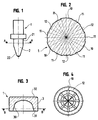
- a first embodiment of tool 1, shown in Figure 1 relates more particularly to the field of flow drilling.
- the present device is furthermore characterizes in that said ceramic tool is defined by a flow drilling forest comprising on the surface reliefs formed by an alternation.
- the tool 1 is defined by a forest 2 comprising on the surface reliefs formed, as visible in FIG. 2, by a regular alternation of projections 10, 11 of thicknesses successively increasing then decreasing. As it happens, these are three projections 10 having a first thickness and framed by projections 11 (two in the embodiment illustrated), having a second thickness, less than the first. These protrusions 11, of smaller thickness between two protrusions 10, delimiting, each in pairs, a groove 12.
- the grooves 12 and the projections 10, 11 defining the relief at the surface of the drill 2 preferably have a width which goes shrinking from the base 21, 31 to the top 22, 32 of the tool 1 ceramic.
- Such a tool 1 makes it possible to drill holes in very fine holes in which can be tapped directly, without no other material or welding input. Moreover, internally to these tubes, around these fluopercer holes, it does not appear, as is customary with other types tools, material removal, in the form of burrs, likely to come off.
- tool 1 is designed as a concave matrix 3 defining a kind of case inside which the part to work is apt to be introduced.
- Said matrix comprises an internal wall 30 of shape substantially ogival which presents, on the surface, an alternation of projections 10 and grooves 12 arranged radially around said wall 30, the width of which is narrowing by the base 31 towards the top 32, and which allow, such as previously described, to reach the temperature very quickly creep, through simple friction at high speed, tool 1 on said part.
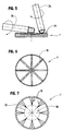
- tool 1 is more in the form of a disc which, on its active face 33, has grooves 12 and / or projections 10 radial, this active face 33 being planar or concave as visible in figure 5.
- the embodiment corresponding to FIG. 7 is distinguished that of FIGS. 5 and 6 in that the icing tool 1, substantially disc-shaped, has an active face 33 plane comprising, in a peripheral zone 35, projections 10 and / or grooves 12, while in a central area 36 it is devoid of roughness.
- the roughness in said zone peripheral 35 is in the form of radial projections 10, in the shape of notches of pyramidal section going down from the periphery to the center of the tool.
- Part icing is carried out quickly, without the need for additional material or weld, avoiding any deposit of scale, and without premature deterioration of the tool 1.
- the present invention therefore provides clear progress in the technical field under consideration.
- tool 1 can, if necessary, be designed in one piece, allowing it confer exceptional solidity, able to withstand particularly severe constraints.
Landscapes
- Engineering & Computer Science (AREA)
- Mechanical Engineering (AREA)
- Earth Drilling (AREA)
- Ceramic Products (AREA)
- Organic Low-Molecular-Weight Compounds And Preparation Thereof (AREA)
- Catalysts (AREA)
- ing And Chemical Polishing (AREA)
Abstract
Description
- la figure 1 correspond à une vue schématique en coupe longitudinale d'une première forme de réalisation d'un outil de fluoperçage tel que mis en oeuvre dans le présent dispositif ;
- la figure 2 est une représentation schématique, en coupe selon A-A, de l'outil représenté à la figure 1 ;
- la figure 3 correspond à une vue schématique en coupe longitudinale d'une seconde forme de réalisation d'un outil tel que mis en oeuvre dans le présent dispositif, cet outil étant plus particulièrement adapté à l'ogivage de pièce ;
- la figure 4 est une représentation schématique, en coupe selon B-B, de l'outil représenté à la figure 3 ;
- la figure 5 est une illustration schématisée de la mise en oeuvre du dispositif selon l'invention pour l'ogivage d'un tube au moyen d'un outil d'ogivage conforme à un autre exemple de réalisation ;
- la figure 6 est une vue schématisée en plan de l'outil illustré dans la figure 5 ;
- la figure 7 est une vue similaire à la figue 6 représentant encore un autre mode de réalisation d'un tel outil d'ogivage.
Claims (12)
- Dispositif utilisé pour l'ogivage, le fluotournage, ou le fluoperçage de pièces métalliques de section ronde et/ou ovoïde, du type comprenant au moins un outil (1) en céramique appliqué sur ladite pièce à ogiver, fluotourner, ou fluopercer et apte à être animé d'un mouvement de translation et/ou de rotation tandis que ladite pièce métallique est animée d'un mouvement de rotation autour de son axe principal, caractérisé en ce que ledit outil (1) en céramique comporte, en surface, une succession de reliefs formant, selon le cas, des saillies (10, 11) et/ou des rainures (12), de manière à produire une augmentation de la température de ladite pièce lors de l'ogivage, du fluotournage, ou du fluoperçage.
- Dispositif selon la revendication 1, caractérisé en ce que lesdites rainures (12) et lesdites saillies (10, 11) formant la succession de reliefs sur la surface dudit outil (1) en céramique présentent, selon le cas, une profondeur ou une épaisseur comprises entre 0,2 mm et 0,5 mm.
- Dispositif selon l'une quelconque des revendications 1 ou 2, caractérisé en ce que ledit outil (1) en céramique est défini par un foret (2) de fluoperçage comprenant en surface des reliefs formés par une alternance régulière de saillies (10, 11) d'épaisseurs successivement croissantes puis décroissantes.
- Dispositif selon la revendication 3, caractérisé en ce que lesdits reliefs sont formés par une alternance régulière de saillies (10) présentant une première épaisseur et de part et d'autre desquelles sont est ménagée des saillies (11) présentant une seconde épaisseur, inférieure à ladite première épaisseur, et délimitant deux par deux à chaque fois une rainure (12).
- Dispositif selon l'une quelconque des revendications 1 ou 2, caractérisé en ce que ledit outil (1) est défini par une matrice (3) concave, dont la paroi interne (30) de forme sensiblement ogivale présente, en surface, une alternance de sillons (10) et de rainures (12) disposés de manière radiale autour de ladite paroi (30).
- Dispositif selon l'une quelconque des revendications 3 à 5, caractérisé en ce que la largeur desdites rainures (30) et desdites saillies (10,11) va rétrécissant de la base (21, 31) vers le sommet (22, 32) de l'outil (1) en céramique.
- Dispositif selon l'une quelconque des revendications 1 ou 2, caractérisé en ce que ledit outil (1) pour l'ogivage d'une pièce (34) se présente sous forme d'un disque comportant une face active (33) plane ou de forme concave.
- Dispositif selon la revendication 7, caractérisé en ce que les rainures (12) et/ou les saillies (10) s'étendent radialement au niveau de face active (33) de l'outil (1).
- Dispositif selon la revendication 7 ou 8, caractérisé en ce que les saillies (10) et/ou rainures (12) son ménagées au niveau d'une zone périphérique (35) de la face active (34) de l'outil (1) .
- Dispositif selon l'une quelconque des revendications précédentes, caractérisé en ce que ledit outil (1) en céramique est réalisé d'une seule pièce.
- Dispositif selon l'une quelconque des revendications 1 à 9, caractérisé en ce que ledit outil (1) est réalisé à partir d'une pluralité d'éléments assemblés.
- Application d'un dispositif selon l'une quelconque des revendications précédentes pour la conception d'éléments entrant dans la composition de lignes d'échappement de véhicules automobiles.
Applications Claiming Priority (2)
| Application Number | Priority Date | Filing Date | Title |
|---|---|---|---|
| FR0301452A FR2850889B1 (fr) | 2003-02-07 | 2003-02-07 | Dispositif utilise pour l'ogivage, le fluotournage, ou le fluopercage de pieces metalliques de section ronde et/ou ovoide |
| FR0301452 | 2003-02-07 |
Publications (2)
| Publication Number | Publication Date |
|---|---|
| EP1447152A1 true EP1447152A1 (fr) | 2004-08-18 |
| EP1447152B1 EP1447152B1 (fr) | 2011-06-22 |
Family
ID=32669342
Family Applications (1)
| Application Number | Title | Priority Date | Filing Date |
|---|---|---|---|
| EP04300069A Expired - Lifetime EP1447152B1 (fr) | 2003-02-07 | 2004-02-09 | outil pour l'ogivage, le fluotournage, ou le fluoperçage de pièces métalliques de section ronde et/ou ovoide |
Country Status (3)
| Country | Link |
|---|---|
| EP (1) | EP1447152B1 (fr) |
| AT (1) | ATE513634T1 (fr) |
| FR (1) | FR2850889B1 (fr) |
Cited By (1)
| Publication number | Priority date | Publication date | Assignee | Title |
|---|---|---|---|---|
| FR2941638A1 (fr) * | 2009-02-04 | 2010-08-06 | Inter Meca | Procede de generation d'un bourrelet dans une piece a paroi mince. |
Families Citing this family (1)
| Publication number | Priority date | Publication date | Assignee | Title |
|---|---|---|---|---|
| CN106334722B (zh) * | 2016-08-31 | 2018-04-06 | 广州沃福模具有限公司 | 一种生产套管的冷冲压方法 |
Citations (9)
| Publication number | Priority date | Publication date | Assignee | Title |
|---|---|---|---|---|
| FR761102A (fr) * | 1933-02-27 | 1934-03-12 | R A M S Metal Works Ltd | Perfectionnements à la fabrication des bacs métalliques cylindriques, spécialement des bacs en zinc pour cellules de batteries électriques sèches |
| US3939683A (en) * | 1974-11-28 | 1976-02-24 | Geffen Johannes Adrianus Van | Piercing tools |
| CH586078A5 (fr) * | 1974-05-10 | 1977-03-31 | Geffen Tech Handels En Adviesb | |
| US4132097A (en) * | 1977-11-03 | 1979-01-02 | Tridan Tool & Machine, Inc. | Method for forming collared holes |
| GB2069386A (en) * | 1980-02-18 | 1981-08-26 | British Steel Corp | Rotary piercing tools |
| GB2091610A (en) * | 1981-01-21 | 1982-08-04 | Hiby Friedrich Karl | Flow drilling tools |
| EP0057039A1 (fr) * | 1981-01-22 | 1982-08-04 | Flowdrill B.V. | Outil de perçage par fluage pour faire des trous dans des tôles |
| US4428214A (en) * | 1982-02-08 | 1984-01-31 | Deere & Company | Flow drilling process and tool therefor |
| US4454741A (en) * | 1982-02-19 | 1984-06-19 | Flowdrill B.V. | Flow drill for the provision of holes in sheet material |
-
2003
- 2003-02-07 FR FR0301452A patent/FR2850889B1/fr not_active Expired - Fee Related
-
2004
- 2004-02-09 EP EP04300069A patent/EP1447152B1/fr not_active Expired - Lifetime
- 2004-02-09 AT AT04300069T patent/ATE513634T1/de not_active IP Right Cessation
Patent Citations (9)
| Publication number | Priority date | Publication date | Assignee | Title |
|---|---|---|---|---|
| FR761102A (fr) * | 1933-02-27 | 1934-03-12 | R A M S Metal Works Ltd | Perfectionnements à la fabrication des bacs métalliques cylindriques, spécialement des bacs en zinc pour cellules de batteries électriques sèches |
| CH586078A5 (fr) * | 1974-05-10 | 1977-03-31 | Geffen Tech Handels En Adviesb | |
| US3939683A (en) * | 1974-11-28 | 1976-02-24 | Geffen Johannes Adrianus Van | Piercing tools |
| US4132097A (en) * | 1977-11-03 | 1979-01-02 | Tridan Tool & Machine, Inc. | Method for forming collared holes |
| GB2069386A (en) * | 1980-02-18 | 1981-08-26 | British Steel Corp | Rotary piercing tools |
| GB2091610A (en) * | 1981-01-21 | 1982-08-04 | Hiby Friedrich Karl | Flow drilling tools |
| EP0057039A1 (fr) * | 1981-01-22 | 1982-08-04 | Flowdrill B.V. | Outil de perçage par fluage pour faire des trous dans des tôles |
| US4428214A (en) * | 1982-02-08 | 1984-01-31 | Deere & Company | Flow drilling process and tool therefor |
| US4454741A (en) * | 1982-02-19 | 1984-06-19 | Flowdrill B.V. | Flow drill for the provision of holes in sheet material |
Cited By (1)
| Publication number | Priority date | Publication date | Assignee | Title |
|---|---|---|---|---|
| FR2941638A1 (fr) * | 2009-02-04 | 2010-08-06 | Inter Meca | Procede de generation d'un bourrelet dans une piece a paroi mince. |
Also Published As
| Publication number | Publication date |
|---|---|
| ATE513634T1 (de) | 2011-07-15 |
| EP1447152B1 (fr) | 2011-06-22 |
| FR2850889B1 (fr) | 2006-03-24 |
| FR2850889A1 (fr) | 2004-08-13 |
Similar Documents
| Publication | Publication Date | Title |
|---|---|---|
| EP2981371B1 (fr) | Procédé de fabrication d'une pièce métallique tubulaire | |
| FR2541409A1 (fr) | Poulies a gorges trapezoidales multiples faites de tole et leur procede de fabrication | |
| FR2608078A1 (fr) | Procede pour fabriquer une denture helicoidale interieure | |
| FR3031779A1 (fr) | ||
| EP1447152B1 (fr) | outil pour l'ogivage, le fluotournage, ou le fluoperçage de pièces métalliques de section ronde et/ou ovoide | |
| FR2580341A1 (fr) | Procede de realisation d'une liaison rigide entre deux pieces mecaniques coaxiales, et ensemble de deux pieces liees par ce procede | |
| EP0220769B1 (fr) | Procédé pour la réalisation d'un ressort de type cylindrique utilisable aux hautes températures | |
| EP4147817A1 (fr) | Procede d'assemblage d'au moins une bague cooperant par frettage avec une portee de frettage d'une piece | |
| FR2790981A1 (fr) | Procede de production d'un tube en alliage a base de fer a durcissement par phase dispersee | |
| EP1771587A2 (fr) | Procédé de réalisation d'un arbre de lanceur de démarreur | |
| EP0517572B2 (fr) | Procédé de fabrication d'une poulie, dispositif pour la mise en oeuvre et poulie obtenue | |
| WO2003092941A1 (fr) | Procede de rainurage de l'alesage d'un tube et porte outil de rainurage | |
| EP0203866B1 (fr) | Filière pour filage à chaud | |
| FR2828419A1 (fr) | Outil, machine et procede de formage a froid, perfectionnes | |
| EP1935528A1 (fr) | Procédé d'assemblage d'une bague de roulement avec un organe mécanique | |
| EP0661136B1 (fr) | Procédé de rodage de la surface d'une pièce et rodoir pour la mise en oeuvre de ce procédé | |
| FR3057625B1 (fr) | Lanceur pour demarreur de vehicule automobile a moteur thermique | |
| EP3636942A1 (fr) | Proce de de fabrication d'une cage monobloc massive de roulement a rotule, cage et roulement a rotule associe s | |
| FR2906355A1 (fr) | Tube pour echangeur de chaleur,echangeur comportant un tel tube et procede de fabrication d'un tel tube | |
| FR2748677A1 (fr) | Procede de forgeage a froid pour fabriquer des moyeux d'embrayages de vehicules automobiles | |
| CH338299A (fr) | Procédé et appareil pour la fabrication continue d'une pièce tubulaire | |
| FR3166562A1 (fr) | Procédé de fabrication d’un arbre de turbine en acier haute résistance | |
| EP2476541A1 (fr) | Procede d'amelioration des proprietes mecaniques d'un assemblage en materiau composite | |
| FR2766748A1 (fr) | Procede de fabrication d'une pluralite de pieces metalliques par rupture fragile d'une preebauche d'une pluralite de pieces | |
| FR2501540A1 (fr) | Cylindre de laminage |
Legal Events
| Date | Code | Title | Description |
|---|---|---|---|
| PUAI | Public reference made under article 153(3) epc to a published international application that has entered the european phase |
Free format text: ORIGINAL CODE: 0009012 |
|
| AK | Designated contracting states |
Kind code of ref document: A1 Designated state(s): AT BE BG CH CY CZ DE DK EE ES FI FR GB GR HU IE IT LI LU MC NL PT RO SE SI SK TR |
|
| AX | Request for extension of the european patent |
Extension state: AL LT LV MK |
|
| AKX | Designation fees paid | ||
| REG | Reference to a national code |
Ref country code: DE Ref legal event code: 8566 |
|
| 17P | Request for examination filed |
Effective date: 20050509 |
|
| RBV | Designated contracting states (corrected) |
Designated state(s): AT BE BG CH CY CZ DE DK EE ES FI FR GB GR HU IE IT LI LU MC NL PT RO SE SI SK TR |
|
| 17Q | First examination report despatched |
Effective date: 20070312 |
|
| GRAP | Despatch of communication of intention to grant a patent |
Free format text: ORIGINAL CODE: EPIDOSNIGR1 |
|
| RTI1 | Title (correction) |
Free format text: TOOL FOR FORMING IN OGIVE LIKE FORM, FOR SPINNING OR FLUOPIERCING OF PIECES OF A ROUND OR OVOID SECTION |
|
| GRAS | Grant fee paid |
Free format text: ORIGINAL CODE: EPIDOSNIGR3 |
|
| GRAA | (expected) grant |
Free format text: ORIGINAL CODE: 0009210 |
|
| AK | Designated contracting states |
Kind code of ref document: B1 Designated state(s): AT BE BG CH CY CZ DE DK EE ES FI FR GB GR HU IE IT LI LU MC NL PT RO SE SI SK TR |
|
| REG | Reference to a national code |
Ref country code: GB Ref legal event code: FG4D Free format text: NOT ENGLISH |
|
| REG | Reference to a national code |
Ref country code: CH Ref legal event code: EP |
|
| REG | Reference to a national code |
Ref country code: IE Ref legal event code: FG4D Free format text: LANGUAGE OF EP DOCUMENT: FRENCH |
|
| REG | Reference to a national code |
Ref country code: DE Ref legal event code: R096 Ref document number: 602004033167 Country of ref document: DE Effective date: 20110728 |
|
| REG | Reference to a national code |
Ref country code: NL Ref legal event code: VDEP Effective date: 20110622 |
|
| PG25 | Lapsed in a contracting state [announced via postgrant information from national office to epo] |
Ref country code: SE Free format text: LAPSE BECAUSE OF FAILURE TO SUBMIT A TRANSLATION OF THE DESCRIPTION OR TO PAY THE FEE WITHIN THE PRESCRIBED TIME-LIMIT Effective date: 20110622 |
|
| PG25 | Lapsed in a contracting state [announced via postgrant information from national office to epo] |
Ref country code: GR Free format text: LAPSE BECAUSE OF FAILURE TO SUBMIT A TRANSLATION OF THE DESCRIPTION OR TO PAY THE FEE WITHIN THE PRESCRIBED TIME-LIMIT Effective date: 20110923 Ref country code: FI Free format text: LAPSE BECAUSE OF FAILURE TO SUBMIT A TRANSLATION OF THE DESCRIPTION OR TO PAY THE FEE WITHIN THE PRESCRIBED TIME-LIMIT Effective date: 20110622 Ref country code: SI Free format text: LAPSE BECAUSE OF FAILURE TO SUBMIT A TRANSLATION OF THE DESCRIPTION OR TO PAY THE FEE WITHIN THE PRESCRIBED TIME-LIMIT Effective date: 20110622 Ref country code: CY Free format text: LAPSE BECAUSE OF FAILURE TO SUBMIT A TRANSLATION OF THE DESCRIPTION OR TO PAY THE FEE WITHIN THE PRESCRIBED TIME-LIMIT Effective date: 20110622 Ref country code: AT Free format text: LAPSE BECAUSE OF FAILURE TO SUBMIT A TRANSLATION OF THE DESCRIPTION OR TO PAY THE FEE WITHIN THE PRESCRIBED TIME-LIMIT Effective date: 20110622 |
|
| PG25 | Lapsed in a contracting state [announced via postgrant information from national office to epo] |
Ref country code: NL Free format text: LAPSE BECAUSE OF FAILURE TO SUBMIT A TRANSLATION OF THE DESCRIPTION OR TO PAY THE FEE WITHIN THE PRESCRIBED TIME-LIMIT Effective date: 20110622 |
|
| REG | Reference to a national code |
Ref country code: IE Ref legal event code: FD4D |
|
| PG25 | Lapsed in a contracting state [announced via postgrant information from national office to epo] |
Ref country code: CZ Free format text: LAPSE BECAUSE OF FAILURE TO SUBMIT A TRANSLATION OF THE DESCRIPTION OR TO PAY THE FEE WITHIN THE PRESCRIBED TIME-LIMIT Effective date: 20110622 Ref country code: EE Free format text: LAPSE BECAUSE OF FAILURE TO SUBMIT A TRANSLATION OF THE DESCRIPTION OR TO PAY THE FEE WITHIN THE PRESCRIBED TIME-LIMIT Effective date: 20110622 Ref country code: PT Free format text: LAPSE BECAUSE OF FAILURE TO SUBMIT A TRANSLATION OF THE DESCRIPTION OR TO PAY THE FEE WITHIN THE PRESCRIBED TIME-LIMIT Effective date: 20111024 Ref country code: IE Free format text: LAPSE BECAUSE OF FAILURE TO SUBMIT A TRANSLATION OF THE DESCRIPTION OR TO PAY THE FEE WITHIN THE PRESCRIBED TIME-LIMIT Effective date: 20110622 |
|
| PG25 | Lapsed in a contracting state [announced via postgrant information from national office to epo] |
Ref country code: RO Free format text: LAPSE BECAUSE OF FAILURE TO SUBMIT A TRANSLATION OF THE DESCRIPTION OR TO PAY THE FEE WITHIN THE PRESCRIBED TIME-LIMIT Effective date: 20110622 Ref country code: SK Free format text: LAPSE BECAUSE OF FAILURE TO SUBMIT A TRANSLATION OF THE DESCRIPTION OR TO PAY THE FEE WITHIN THE PRESCRIBED TIME-LIMIT Effective date: 20110622 |
|
| PLBE | No opposition filed within time limit |
Free format text: ORIGINAL CODE: 0009261 |
|
| STAA | Information on the status of an ep patent application or granted ep patent |
Free format text: STATUS: NO OPPOSITION FILED WITHIN TIME LIMIT |
|
| 26N | No opposition filed |
Effective date: 20120323 |
|
| PG25 | Lapsed in a contracting state [announced via postgrant information from national office to epo] |
Ref country code: IT Free format text: LAPSE BECAUSE OF FAILURE TO SUBMIT A TRANSLATION OF THE DESCRIPTION OR TO PAY THE FEE WITHIN THE PRESCRIBED TIME-LIMIT Effective date: 20110622 |
|
| PG25 | Lapsed in a contracting state [announced via postgrant information from national office to epo] |
Ref country code: DK Free format text: LAPSE BECAUSE OF FAILURE TO SUBMIT A TRANSLATION OF THE DESCRIPTION OR TO PAY THE FEE WITHIN THE PRESCRIBED TIME-LIMIT Effective date: 20110622 |
|
| REG | Reference to a national code |
Ref country code: DE Ref legal event code: R097 Ref document number: 602004033167 Country of ref document: DE Effective date: 20120323 |
|
| BERE | Be: lapsed |
Owner name: INTER MECA (SOCIETE A RESPONSABILITE LIMITEE) Effective date: 20120228 |
|
| PG25 | Lapsed in a contracting state [announced via postgrant information from national office to epo] |
Ref country code: MC Free format text: LAPSE BECAUSE OF NON-PAYMENT OF DUE FEES Effective date: 20120229 |
|
| REG | Reference to a national code |
Ref country code: CH Ref legal event code: PL |
|
| GBPC | Gb: european patent ceased through non-payment of renewal fee |
Effective date: 20120209 |
|
| PG25 | Lapsed in a contracting state [announced via postgrant information from national office to epo] |
Ref country code: LI Free format text: LAPSE BECAUSE OF NON-PAYMENT OF DUE FEES Effective date: 20120229 Ref country code: CH Free format text: LAPSE BECAUSE OF NON-PAYMENT OF DUE FEES Effective date: 20120229 |
|
| PG25 | Lapsed in a contracting state [announced via postgrant information from national office to epo] |
Ref country code: BE Free format text: LAPSE BECAUSE OF NON-PAYMENT OF DUE FEES Effective date: 20120228 |
|
| PG25 | Lapsed in a contracting state [announced via postgrant information from national office to epo] |
Ref country code: GB Free format text: LAPSE BECAUSE OF NON-PAYMENT OF DUE FEES Effective date: 20120209 |
|
| PG25 | Lapsed in a contracting state [announced via postgrant information from national office to epo] |
Ref country code: ES Free format text: LAPSE BECAUSE OF FAILURE TO SUBMIT A TRANSLATION OF THE DESCRIPTION OR TO PAY THE FEE WITHIN THE PRESCRIBED TIME-LIMIT Effective date: 20111003 |
|
| PGFP | Annual fee paid to national office [announced via postgrant information from national office to epo] |
Ref country code: DE Payment date: 20130219 Year of fee payment: 10 Ref country code: FR Payment date: 20130314 Year of fee payment: 10 |
|
| PG25 | Lapsed in a contracting state [announced via postgrant information from national office to epo] |
Ref country code: BG Free format text: LAPSE BECAUSE OF FAILURE TO SUBMIT A TRANSLATION OF THE DESCRIPTION OR TO PAY THE FEE WITHIN THE PRESCRIBED TIME-LIMIT Effective date: 20110922 |
|
| PG25 | Lapsed in a contracting state [announced via postgrant information from national office to epo] |
Ref country code: TR Free format text: LAPSE BECAUSE OF FAILURE TO SUBMIT A TRANSLATION OF THE DESCRIPTION OR TO PAY THE FEE WITHIN THE PRESCRIBED TIME-LIMIT Effective date: 20110622 |
|
| PG25 | Lapsed in a contracting state [announced via postgrant information from national office to epo] |
Ref country code: LU Free format text: LAPSE BECAUSE OF NON-PAYMENT OF DUE FEES Effective date: 20120209 |
|
| PG25 | Lapsed in a contracting state [announced via postgrant information from national office to epo] |
Ref country code: HU Free format text: LAPSE BECAUSE OF FAILURE TO SUBMIT A TRANSLATION OF THE DESCRIPTION OR TO PAY THE FEE WITHIN THE PRESCRIBED TIME-LIMIT Effective date: 20040209 |
|
| REG | Reference to a national code |
Ref country code: DE Ref legal event code: R119 Ref document number: 602004033167 Country of ref document: DE |
|
| REG | Reference to a national code |
Ref country code: FR Ref legal event code: ST Effective date: 20141031 |
|
| REG | Reference to a national code |
Ref country code: DE Ref legal event code: R119 Ref document number: 602004033167 Country of ref document: DE Effective date: 20140902 |
|
| PG25 | Lapsed in a contracting state [announced via postgrant information from national office to epo] |
Ref country code: FR Free format text: LAPSE BECAUSE OF NON-PAYMENT OF DUE FEES Effective date: 20140228 Ref country code: DE Free format text: LAPSE BECAUSE OF NON-PAYMENT OF DUE FEES Effective date: 20140902 |