EP1447192A1 - Verfahren und Vorrichtung zum Giessen von Beton - Google Patents
Verfahren und Vorrichtung zum Giessen von Beton Download PDFInfo
- Publication number
- EP1447192A1 EP1447192A1 EP04075425A EP04075425A EP1447192A1 EP 1447192 A1 EP1447192 A1 EP 1447192A1 EP 04075425 A EP04075425 A EP 04075425A EP 04075425 A EP04075425 A EP 04075425A EP 1447192 A1 EP1447192 A1 EP 1447192A1
- Authority
- EP
- European Patent Office
- Prior art keywords
- temperature
- concrete mortar
- container
- concrete
- cooling
- Prior art date
- Legal status (The legal status is an assumption and is not a legal conclusion. Google has not performed a legal analysis and makes no representation as to the accuracy of the status listed.)
- Ceased
Links
- 238000000034 method Methods 0.000 title claims abstract description 56
- 239000004570 mortar (masonry) Substances 0.000 claims abstract description 204
- 238000001816 cooling Methods 0.000 claims description 114
- 238000010438 heat treatment Methods 0.000 claims description 96
- 239000007788 liquid Substances 0.000 claims description 39
- 238000007599 discharging Methods 0.000 claims description 8
- 238000009434 installation Methods 0.000 claims description 8
- 238000005086 pumping Methods 0.000 claims description 8
- 238000009415 formwork Methods 0.000 description 20
- 238000009826 distribution Methods 0.000 description 19
- 238000010276 construction Methods 0.000 description 9
- 230000000694 effects Effects 0.000 description 8
- 238000004088 simulation Methods 0.000 description 7
- XLYOFNOQVPJJNP-UHFFFAOYSA-N water Substances O XLYOFNOQVPJJNP-UHFFFAOYSA-N 0.000 description 7
- 239000000470 constituent Substances 0.000 description 6
- 239000000463 material Substances 0.000 description 6
- 230000008569 process Effects 0.000 description 5
- IJGRMHOSHXDMSA-UHFFFAOYSA-N Atomic nitrogen Chemical compound N#N IJGRMHOSHXDMSA-UHFFFAOYSA-N 0.000 description 4
- 238000006243 chemical reaction Methods 0.000 description 4
- 230000002411 adverse Effects 0.000 description 3
- 239000000203 mixture Substances 0.000 description 3
- 230000008901 benefit Effects 0.000 description 2
- 239000004568 cement Substances 0.000 description 2
- 239000012530 fluid Substances 0.000 description 2
- 238000007710 freezing Methods 0.000 description 2
- 230000008014 freezing Effects 0.000 description 2
- 229910052757 nitrogen Inorganic materials 0.000 description 2
- 230000000704 physical effect Effects 0.000 description 2
- 230000002787 reinforcement Effects 0.000 description 2
- 238000009435 building construction Methods 0.000 description 1
- 230000008859 change Effects 0.000 description 1
- 230000006835 compression Effects 0.000 description 1
- 238000007906 compression Methods 0.000 description 1
- 239000000110 cooling liquid Substances 0.000 description 1
- 238000005336 cracking Methods 0.000 description 1
- 230000003247 decreasing effect Effects 0.000 description 1
- 230000001934 delay Effects 0.000 description 1
- 238000006073 displacement reaction Methods 0.000 description 1
- 238000000605 extraction Methods 0.000 description 1
- 238000007667 floating Methods 0.000 description 1
- 239000007789 gas Substances 0.000 description 1
- 238000002347 injection Methods 0.000 description 1
- 239000007924 injection Substances 0.000 description 1
- 238000012804 iterative process Methods 0.000 description 1
- 238000004519 manufacturing process Methods 0.000 description 1
- 238000012986 modification Methods 0.000 description 1
- 230000004048 modification Effects 0.000 description 1
- 230000001681 protective effect Effects 0.000 description 1
- 230000009467 reduction Effects 0.000 description 1
- 239000000126 substance Substances 0.000 description 1
- 230000007704 transition Effects 0.000 description 1
Images






Classifications
-
- C—CHEMISTRY; METALLURGY
- C04—CEMENTS; CONCRETE; ARTIFICIAL STONE; CERAMICS; REFRACTORIES
- C04B—LIME, MAGNESIA; SLAG; CEMENTS; COMPOSITIONS THEREOF, e.g. MORTARS, CONCRETE OR LIKE BUILDING MATERIALS; ARTIFICIAL STONE; CERAMICS; REFRACTORIES; TREATMENT OF NATURAL STONE
- C04B40/00—Processes, in general, for influencing or modifying the properties of mortars, concrete or artificial stone compositions, e.g. their setting or hardening ability
- C04B40/0075—Processes, in general, for influencing or modifying the properties of mortars, concrete or artificial stone compositions, e.g. their setting or hardening ability making use of a decrease in temperature
-
- B—PERFORMING OPERATIONS; TRANSPORTING
- B28—WORKING CEMENT, CLAY, OR STONE
- B28B—SHAPING CLAY OR OTHER CERAMIC COMPOSITIONS; SHAPING SLAG; SHAPING MIXTURES CONTAINING CEMENTITIOUS MATERIAL, e.g. PLASTER
- B28B17/00—Details of, or accessories for, apparatus for shaping the material; Auxiliary measures taken in connection with such shaping
- B28B17/02—Conditioning the material prior to shaping
-
- B—PERFORMING OPERATIONS; TRANSPORTING
- B28—WORKING CEMENT, CLAY, OR STONE
- B28C—PREPARING CLAY; PRODUCING MIXTURES CONTAINING CLAY OR CEMENTITIOUS MATERIAL, e.g. PLASTER
- B28C5/00—Apparatus or methods for producing mixtures of cement with other substances, e.g. slurries, mortars, porous or fibrous compositions
- B28C5/42—Apparatus specially adapted for being mounted on vehicles with provision for mixing during transport
- B28C5/4203—Details; Accessories
-
- B—PERFORMING OPERATIONS; TRANSPORTING
- B28—WORKING CEMENT, CLAY, OR STONE
- B28C—PREPARING CLAY; PRODUCING MIXTURES CONTAINING CLAY OR CEMENTITIOUS MATERIAL, e.g. PLASTER
- B28C5/00—Apparatus or methods for producing mixtures of cement with other substances, e.g. slurries, mortars, porous or fibrous compositions
- B28C5/46—Arrangements for applying super- or sub-atmospheric pressure during mixing; Arrangements for cooling or heating during mixing, e.g. by introducing vapour
-
- C—CHEMISTRY; METALLURGY
- C04—CEMENTS; CONCRETE; ARTIFICIAL STONE; CERAMICS; REFRACTORIES
- C04B—LIME, MAGNESIA; SLAG; CEMENTS; COMPOSITIONS THEREOF, e.g. MORTARS, CONCRETE OR LIKE BUILDING MATERIALS; ARTIFICIAL STONE; CERAMICS; REFRACTORIES; TREATMENT OF NATURAL STONE
- C04B40/00—Processes, in general, for influencing or modifying the properties of mortars, concrete or artificial stone compositions, e.g. their setting or hardening ability
- C04B40/0082—Processes, in general, for influencing or modifying the properties of mortars, concrete or artificial stone compositions, e.g. their setting or hardening ability making use of a rise in temperature, e.g. caused by an exothermic reaction
-
- E—FIXED CONSTRUCTIONS
- E04—BUILDING
- E04G—SCAFFOLDING; FORMS; SHUTTERING; BUILDING IMPLEMENTS OR AIDS, OR THEIR USE; HANDLING BUILDING MATERIALS ON THE SITE; REPAIRING, BREAKING-UP OR OTHER WORK ON EXISTING BUILDINGS
- E04G21/00—Preparing, conveying, or working-up building materials or building elements in situ; Other devices or measures for constructional work
- E04G21/02—Conveying or working-up concrete or similar masses able to be heaped or cast
- E04G21/04—Devices for both conveying and distributing
-
- E—FIXED CONSTRUCTIONS
- E04—BUILDING
- E04G—SCAFFOLDING; FORMS; SHUTTERING; BUILDING IMPLEMENTS OR AIDS, OR THEIR USE; HANDLING BUILDING MATERIALS ON THE SITE; REPAIRING, BREAKING-UP OR OTHER WORK ON EXISTING BUILDINGS
- E04G21/00—Preparing, conveying, or working-up building materials or building elements in situ; Other devices or measures for constructional work
- E04G21/02—Conveying or working-up concrete or similar masses able to be heaped or cast
- E04G21/04—Devices for both conveying and distributing
- E04G21/0418—Devices for both conveying and distributing with distribution hose
- E04G21/0436—Devices for both conveying and distributing with distribution hose on a mobile support, e.g. truck
-
- C—CHEMISTRY; METALLURGY
- C04—CEMENTS; CONCRETE; ARTIFICIAL STONE; CERAMICS; REFRACTORIES
- C04B—LIME, MAGNESIA; SLAG; CEMENTS; COMPOSITIONS THEREOF, e.g. MORTARS, CONCRETE OR LIKE BUILDING MATERIALS; ARTIFICIAL STONE; CERAMICS; REFRACTORIES; TREATMENT OF NATURAL STONE
- C04B2111/00—Mortars, concrete or artificial stone or mixtures to prepare them, characterised by specific function, property or use
- C04B2111/00034—Physico-chemical characteristics of the mixtures
- C04B2111/00146—Sprayable or pumpable mixtures
Definitions
- cooling conduits A further drawback of using cooling conduits is that the cooling pipe remains in place after the concrete has cured, the cooling liquid must be removed from the pipes and a suitable injection mortar has to be injected into the pipes. Furthermore, the pipes have to be blocked at their mouth. Such a cooling system is therefore complicated, requires many additional operations and has a cost-increasing effect on the total building costs of the construction.
- the method preferably comprises of applying a first quantity of concrete mortar at a relatively low temperature to a relatively cold ground in order to limit the stresses occurring in the poured concrete and applying the second, subsequent quantity of concrete mortar at a relatively high temperature in order to shorten the curing time of the poured concrete.
- the temperature adjusting means also or instead comprise:
- liquids are preferably identical, so that both heating and cooling can be carried out with a single liquid.
- the container comprises a rotatably driven mixing drum provided with one or more mixing blades and the temperature adjusting means comprise one or more liquid conduits arranged in or on the blades.
- the container comprises a receiving bin of a truck and the temperature adjusting means comprise one or more cooling and/or heating conduits arranged along the container wall.
- the container comprises two or more tubes arranged in zigzag arrangement.
- the container, and thereby the vehicle on which the container is placed can have a relatively short length, while a sufficient cooling and/or heating capacity is still ensured.
- the number of tubes to be applied can herein be varied subject to the required degree of heating.
- the device comprises control means which are adapted to adjust the temperature of the concrete mortar for pouring to a temperature which differs by less than a set maximum temperature difference from the temperature of the ground.
- the maximum temperature difference preferably amounts to 25°C during cooling and to 40°C during heating, and preferably to 15°C during cooling and to 30°C during heating.
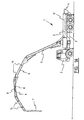
- Figure 1a shows a view of a first preferred embodiment of a device according to the invention.
- Figure 1a shows a mobile pumping installation 1 with which plastic concrete mortar can be cooled and heated.
- plastic is usual in the field to denote all concrete mortar that has not yet cured.
- the term “plastic concrete mortar” should therefore not only be understood to mean concrete mortar which is in a kneadable or deformable state, but also includes concrete mortar in a liquid and/or viscous state.
- elements 8 Placed at one or more positions in the tube along the tube wall thereof are elements 8 with which the concrete mortar flowing therealong can be cooled and/or heated.
- the elements can be combined cooling/heating elements with which cooling or heating can be performed as required.
- the elements can however also be separate cooling elements and separate heating elements.
- the elements comprise conduits through which liquid of a suitable temperature passes. By heat transfer via the liquid and the conduit wall to the concrete mortar in the concrete mortar supply tube or by extraction of heat from the concrete mortar via the conduit wall to the liquid in said conduits, the temperature of the concrete mortar can be brought to and held at a desired value.
- cooling/heating elements 8 are arranged in a single tube segment 6. It is however also possible to arrange such cooling/heating elements in two or more tube segments 6. It is also possible to provide cooling/heating elements 8' (shown in broken lines) in the load platform 3 of truck 2 or in one of the other tube segments 6.
- FIG. 1a further shows in schematic manner that the concrete mortar supply tube can be provided with a number of temperature sensors 15, 16. Temperature sensors 15 are preferably arranged downstream of cooling/heating elements 8. On the basis of the temperature sensors 15 the temperature of the concrete mortar flowing past can be determined. Control means (not shown) can control cooling/heating elements 8 subject to the thus determined temperature. When the mixture flowing past temperature sensors 15 is for instance too cool, the activity of cooling elements 8 can be reduced and/or the activity of heating elements 8 can be increased. If, conversely, the temperature of the mixture flowing past temperature sensors 15 is too high, the activity of cooling elements 8 and heating elements 8 can be increased respectively reduced. Such control takes place such that the temperature can be adjusted and held (within predetermined limits) at a desired value. Even if the ambient conditions change for instance when the outside temperature is subject to great fluctuations, the concrete mortar can be held at an almost constant value.
- Temperature sensors 16 are on the other hand provided downstream relative to the cooling/heating elements 8. These temperature sensors 16 are also connected to control means (not shown), with which the activity of the cooling/heating elements 8 can be controlled.
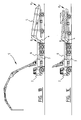
- FIG. 1b shows another embodiment, in which the cooling or heating of concrete mortar takes place in a cooling and/or heating unit 5 which is provided with a container and which can be placed between a truck mixer (not shown) (inlet point A, truck mixer without cooling/heating module) and a concrete pump or cable 17 and the like (outlet point B, pump without cooling/heating module).
- the heating unit comprises a frame 20 on which a container 21 is disposed at an angle.
- the container is provided with blades with which the mortar can be displaced. Cooling or heating of the concrete mortar takes place by providing the blades in the container and/or the wall of the container with cooling/heating conduits which are connected to a cooling/heating module.
- the tubes have a predetermined length (about 6 m) and have a more or less fixed cooling and/or heating capacity.
- the number of tubes 22 applied depends on the required degree of cooling or heating. If the concrete mortar only has to be heated or cooled a little, a small number (for instance 2 tubes) will suffice, while at a greater required cooling capacity the number of tubes is larger (for instance 3 or more).
- the frame is embodied herein such that the number of tubes 22 applied and the angle at which they extend can vary.
- Another embodiment (not shown) relates to a combination of the embodiment described above with reference to figure 1c (cooling and/or heating with jacks) which is integrated into the installation of a stationary or mobile concrete mixing plant.
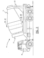
- FIG 2 Shown in figure 2 is another preferred embodiment of the device according to the invention.
- the figure shows a truck mixer 9 consisting of a truck 10 provided with a rotatable drum 11.
- Drum 11 is mounted rotatably in a frame 12, 13 mounted on truck 10.
- the rotating movement of drum 11 is driven in known manner by an electric motor (not shown).
- Figure 3 shows a cross-section at location III-III through drum 11 of truck mixer 9.
- the cross-section shows a drum 11 which is provided on the inside with three curved blades 12.
- Arranged in blades 12 are elements 13 with which concrete mortar b possibly present in drum 11 can be heated respectively cooled.
- FIG 4 shows an alternative embodiment in which cooling/heating elements 14 are provided in wall 11 of the drum instead of in blades 12.
- Other embodiments in which cooling/heating elements 13 and 14 are arranged in both wall 11 and blades 12 are however also possible.
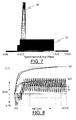
- the simulation also comprises of visualizing the difference in the build-up of stress between the different above mentioned method embodiments. The simulations were carried out for two situations.
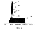
- a wall 36 is arranged on a relatively cold ground of an already poured concrete floor 35 by pouring concrete mortar into a formwork suitable for this purpose.
- a system of eight cooling pipes 30 which, once the mortar has been poured, can cool the concrete wall from the inside.
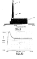
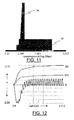
- a second situation (figures 9-12) relates to the same configuration, although here the concrete mortar for pouring is cooled according to the ) invention.
- the values of a number of parameters used in the simulation are listed.
- curves C and D show the stress variation at respectively position x1 and position x2.
- ⁇ designates tensile stresses
- ⁇ designates compression stresses.
- Curve M1 shows the developed tensile stress in the concrete
- curve M2 shows the maximum permissible stress which may occur in the concrete (with a 50% safety margin). In practice the average stresses occurring in the wall should remain below the curve M2.
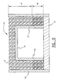
- Figure 13 shows an example of an application of the device according to the invention. Shown is a cross-section through a tunnel casing. Wall formwork elements 32 and 33 are arranged on a relatively cold floor 31, while a roof formwork 34 is provided on top of wall formwork 33.
- the concrete mortar is poured form above (arrow P2) into the space formed ) by the formwork elements 32, 33 and 34. So as to avoid excessive stress differences between the relatively cold ground 31 and the relatively warm concrete mortar b, the concrete mortar which comes to lie directly on floor 31 is cooled during pouring to a temperature which does not differ too much from that of floor 31. This means a reduction in the stresses occurring in the walls.
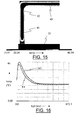
- Figure 14 shows the tunnel cross-section of figure 13 in more detail. A simulation has also been carried out for this configuration.
- the standing wall of the tunnel is divided into two sections 41 and 42, while the roof is defined as section 43.
- figure 16 shows the temperature variation in time at positions x1 and x3, when the tunnel wall and the tunnel roof are manufactured from uncooled concrete mortar.
- the position x1 corresponds to the above mentioned position x1 in the wall
- position x3 is situated roughly at the location of the connection of tunnel roof 43 to tunnel wall 41, 42.
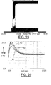
- Figure 18 shows that the stress variation as a function of time at positions x1 and x3 reaches values which exceed the maximum permissible curve M2. On average the values of the stress at position x3 fall below the curve M2, but the values at position x1 far exceed the maximum permissible values according to curve M2. This is an unacceptable situation.
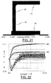
- Figures 19-22 show the situation in which a system of cooling pipes is applied. In this situation the temperature and stress are determined at three positions. Positions x1 and x3 correspond with positions x1 and x3 of figure 14. Position x2 is situated about halfway between positions x1 and x3, at the location of the transition from the upper section 42 to the lower section 41. Clearly shown is that the average stress variation in time at positions x1, x2 and x3 remains below the maximum permissible curve M2.
- These figures, and particularly figure 26, show that the average values of the stresses occurring in time fall on average below the values of the maximum permissible curve M2. This means that in the case cooled concrete mortar is used to arrange the lower section 41, the stresses always remain below the maximum permissible stress values.
- Comparison of figure 24 with figure 20 furthermore shows that at the location of position x3, i.e. between the tunnel wall and the tunnel roof, the temperatures are higher since the concrete mortar of a higher temperature is applied to manufacture this part of the construction. This has the consequence that the upper parts of the construction, i.e. the upper section 42 and tunnel roof 43, will cure much more rapidly than in the case where cooling pipes are applied.
- the ground is formed by a concrete floor.
- the ground can however also be another random structural element.
- the ground is for instance formed by the upright wall.
Landscapes
- Engineering & Computer Science (AREA)
- Chemical & Material Sciences (AREA)
- Structural Engineering (AREA)
- Ceramic Engineering (AREA)
- Mechanical Engineering (AREA)
- Architecture (AREA)
- Materials Engineering (AREA)
- Organic Chemistry (AREA)
- Civil Engineering (AREA)
- Chemical Kinetics & Catalysis (AREA)
- On-Site Construction Work That Accompanies The Preparation And Application Of Concrete (AREA)
Applications Claiming Priority (4)
| Application Number | Priority Date | Filing Date | Title |
|---|---|---|---|
| NL1022669A NL1022669C1 (nl) | 2003-02-13 | 2003-02-13 | Werkwijze en inrichting voor het storten van beton. |
| NL1022669 | 2003-02-13 | ||
| NL1023757A NL1023757C2 (nl) | 2003-02-13 | 2003-06-26 | Werkwijze en inrichting voor het storten van beton. |
| NL1023757 | 2003-06-26 |
Publications (1)
| Publication Number | Publication Date |
|---|---|
| EP1447192A1 true EP1447192A1 (de) | 2004-08-18 |
Family
ID=32684354
Family Applications (1)
| Application Number | Title | Priority Date | Filing Date |
|---|---|---|---|
| EP04075425A Ceased EP1447192A1 (de) | 2003-02-13 | 2004-02-10 | Verfahren und Vorrichtung zum Giessen von Beton |
Country Status (2)
| Country | Link |
|---|---|
| EP (1) | EP1447192A1 (de) |
| NL (1) | NL1023757C2 (de) |
Cited By (8)
| Publication number | Priority date | Publication date | Assignee | Title |
|---|---|---|---|---|
| WO2011089076A1 (en) * | 2010-01-21 | 2011-07-28 | Construction Research & Technology Gmbh | Concrete spraying method using heat recovery |
| WO2014146584A1 (zh) * | 2013-03-21 | 2014-09-25 | 湖南三一智能控制设备有限公司 | 布料车 |
| JP2018031157A (ja) * | 2016-08-24 | 2018-03-01 | みらい建設工業株式会社 | コンクリートひび割れ制御方法 |
| CN110306439A (zh) * | 2019-07-08 | 2019-10-08 | 浙江海洋大学 | 一种桥梁施工用混凝土浇筑设备 |
| CN112976305A (zh) * | 2021-03-04 | 2021-06-18 | 天造机器人科技(广东)有限公司 | 一种基于自动化技术的现浇体系 |
| WO2022175232A1 (de) * | 2021-02-16 | 2022-08-25 | Putzmeister Engineering Gmbh | Baustoffvorrichtung und verwendung mindestens eines teilsensors |
| CN115030511A (zh) * | 2022-07-04 | 2022-09-09 | 山东工业职业学院 | 建筑用楼板浇筑方法 |
| WO2022205646A1 (zh) * | 2021-03-31 | 2022-10-06 | 三一汽车制造有限公司 | 工程机械 |
Citations (10)
| Publication number | Priority date | Publication date | Assignee | Title |
|---|---|---|---|---|
| JPS492153A (de) * | 1972-04-21 | 1974-01-10 | ||
| DE2537173A1 (de) * | 1975-08-21 | 1977-03-10 | Kuehl Hans Joerg | Verfahren und vorrichtung zum kuehlen von frischbeton |
| JPS5938014A (ja) * | 1982-08-25 | 1984-03-01 | 新明和工業株式会社 | コンクリ−トミキサ |
| JPS62122709A (ja) * | 1985-11-25 | 1987-06-04 | 大阪瓦斯株式会社 | コンクリ−トの冷却方法 |
| JPH02132271A (ja) | 1988-11-10 | 1990-05-21 | Maeda Corp | フレッシュコンクリートの冷却方法 |
| JPH06328429A (ja) | 1993-05-26 | 1994-11-29 | Sekisui Chem Co Ltd | セメント材料の原料供給装置 |
| JPH078780A (ja) * | 1993-06-23 | 1995-01-13 | Hitachi Zosen Corp | 攪拌翼 |
| JPH0740334A (ja) * | 1993-07-30 | 1995-02-10 | Mitsui Constr Co Ltd | コンクリート冷却装置 |
| JPH08127021A (ja) | 1994-11-01 | 1996-05-21 | Sekisui Chem Co Ltd | セメントモルタル原料の計量供給装置 |
| EP0879682A1 (de) * | 1997-05-06 | 1998-11-25 | Kabushiki Kaisha Remic-Asano | Verfahren und Vorrichtung zur Verhinderung des Anhaftens und Aushärtens von frischem Beton |
-
2003
- 2003-06-26 NL NL1023757A patent/NL1023757C2/nl not_active IP Right Cessation
-
2004
- 2004-02-10 EP EP04075425A patent/EP1447192A1/de not_active Ceased
Patent Citations (10)
| Publication number | Priority date | Publication date | Assignee | Title |
|---|---|---|---|---|
| JPS492153A (de) * | 1972-04-21 | 1974-01-10 | ||
| DE2537173A1 (de) * | 1975-08-21 | 1977-03-10 | Kuehl Hans Joerg | Verfahren und vorrichtung zum kuehlen von frischbeton |
| JPS5938014A (ja) * | 1982-08-25 | 1984-03-01 | 新明和工業株式会社 | コンクリ−トミキサ |
| JPS62122709A (ja) * | 1985-11-25 | 1987-06-04 | 大阪瓦斯株式会社 | コンクリ−トの冷却方法 |
| JPH02132271A (ja) | 1988-11-10 | 1990-05-21 | Maeda Corp | フレッシュコンクリートの冷却方法 |
| JPH06328429A (ja) | 1993-05-26 | 1994-11-29 | Sekisui Chem Co Ltd | セメント材料の原料供給装置 |
| JPH078780A (ja) * | 1993-06-23 | 1995-01-13 | Hitachi Zosen Corp | 攪拌翼 |
| JPH0740334A (ja) * | 1993-07-30 | 1995-02-10 | Mitsui Constr Co Ltd | コンクリート冷却装置 |
| JPH08127021A (ja) | 1994-11-01 | 1996-05-21 | Sekisui Chem Co Ltd | セメントモルタル原料の計量供給装置 |
| EP0879682A1 (de) * | 1997-05-06 | 1998-11-25 | Kabushiki Kaisha Remic-Asano | Verfahren und Vorrichtung zur Verhinderung des Anhaftens und Aushärtens von frischem Beton |
Non-Patent Citations (3)
| Title |
|---|
| DATABASE WPI Section Ch Week 198728, Derwent World Patents Index; Class J07, AN 1987-194493, XP002263200 * |
| PATENT ABSTRACTS OF JAPAN vol. 014, no. 367 (M - 1008) 9 August 1990 (1990-08-09) * |
| PATENT ABSTRACTS OF JAPAN vol. 1995, no. 05 30 June 1995 (1995-06-30) * |
Cited By (10)
| Publication number | Priority date | Publication date | Assignee | Title |
|---|---|---|---|---|
| WO2011089076A1 (en) * | 2010-01-21 | 2011-07-28 | Construction Research & Technology Gmbh | Concrete spraying method using heat recovery |
| CN102712008A (zh) * | 2010-01-21 | 2012-10-03 | 建筑研究和技术有限公司 | 使用热量回收的混凝土喷射方法 |
| WO2014146584A1 (zh) * | 2013-03-21 | 2014-09-25 | 湖南三一智能控制设备有限公司 | 布料车 |
| JP2018031157A (ja) * | 2016-08-24 | 2018-03-01 | みらい建設工業株式会社 | コンクリートひび割れ制御方法 |
| CN110306439A (zh) * | 2019-07-08 | 2019-10-08 | 浙江海洋大学 | 一种桥梁施工用混凝土浇筑设备 |
| WO2022175232A1 (de) * | 2021-02-16 | 2022-08-25 | Putzmeister Engineering Gmbh | Baustoffvorrichtung und verwendung mindestens eines teilsensors |
| US12546761B2 (en) | 2021-02-16 | 2026-02-10 | Putzmeister Engineering Gmbh | Building material apparatus and use of at least one part sensor |
| CN112976305A (zh) * | 2021-03-04 | 2021-06-18 | 天造机器人科技(广东)有限公司 | 一种基于自动化技术的现浇体系 |
| WO2022205646A1 (zh) * | 2021-03-31 | 2022-10-06 | 三一汽车制造有限公司 | 工程机械 |
| CN115030511A (zh) * | 2022-07-04 | 2022-09-09 | 山东工业职业学院 | 建筑用楼板浇筑方法 |
Also Published As
| Publication number | Publication date |
|---|---|
| NL1023757C2 (nl) | 2004-08-16 |
Similar Documents
| Publication | Publication Date | Title |
|---|---|---|
| CA2200507A1 (en) | Method and apparatus for curing concrete | |
| EP1447192A1 (de) | Verfahren und Vorrichtung zum Giessen von Beton | |
| US9689117B2 (en) | Paving machine | |
| KR101175883B1 (ko) | 콘크리트 양생시 파이프 쿨링 기술을 응용한 변환식 콘크리트 온도차 저감 장치, 그 장치를 이용한 변환식 콘크리트 온도차 저감 양생공법 및 그 공법에 의해 양생된 구조물 | |
| CN113370367B (zh) | 一种组合式uhpc养护方法 | |
| CN106868958B (zh) | 自密实混凝土施工系统及其施工方法 | |
| KR20010017568A (ko) | 콘크리트의 온도균열 저감방법 및 그 장치 | |
| US20090231950A1 (en) | Apparatus for the thermal conditioning of concrete | |
| JP2020196217A (ja) | 吹付けコンクリートの製造方法 | |
| KR102322563B1 (ko) | 온도 제어 기능을 갖는 아스팔트 포설 장비 | |
| CN112252137B (zh) | 一种冬季路面施工用混凝土面层的保温装置 | |
| WO2013079123A1 (en) | A asphalt recycling system and method for producing a new asphalt layer from the asphalt to be recycled | |
| CN114701040A (zh) | 一种双t型预制梁板模具化生产工艺 | |
| CN111962341A (zh) | 一种桥梁段crtsⅲ型板式无砟轨道冬期施工温控方法 | |
| CN111993558A (zh) | 一种钢管混凝土轨枕生产方法 | |
| JP7151042B2 (ja) | コンクリート冷却システム、及びコンクリート冷却方法 | |
| JPH07276342A (ja) | コンクリート二次製品の製造方法及び装置 | |
| KR19990068060A (ko) | 콘크리트믹스플랜트 내 및/또는 콘크리트믹서트럭의 회전식 믹서드럼 내에서 생 콘크리트의 품질유지 및 고착방지방법과 그의 장치. | |
| KR200338562Y1 (ko) | Mspc 제품 제조 장치 | |
| CN115405119B (zh) | 全容式低温储罐外罐壁混凝土冬期内加热外保温施工工艺 | |
| CN113338177A (zh) | 一种小体积混凝土浇筑工艺及装置 | |
| KR200342865Y1 (ko) | Mspc 조성물 이송장치 | |
| CN121519965A (zh) | 一种海底隧道烟道板的安装方法 | |
| CN222294865U (zh) | 一种小断面梯形渠道滑模施工装置 | |
| CN210500830U (zh) | 一种复合自保温砌块的混凝土浆料用混合装置 |
Legal Events
| Date | Code | Title | Description |
|---|---|---|---|
| PUAI | Public reference made under article 153(3) epc to a published international application that has entered the european phase |
Free format text: ORIGINAL CODE: 0009012 |
|
| AK | Designated contracting states |
Kind code of ref document: A1 Designated state(s): AT BE BG CH CY CZ DE DK EE ES FI FR GB GR HU IE IT LI LU MC NL PT RO SE SI SK TR |
|
| AX | Request for extension of the european patent |
Extension state: AL LT LV MK |
|
| 17P | Request for examination filed |
Effective date: 20050121 |
|
| AKX | Designation fees paid |
Designated state(s): AT BE BG CH CY CZ DE DK EE ES FI FR GB GR HU IE IT LI LU MC NL PT RO SE SI SK TR |
|
| 17Q | First examination report despatched |
Effective date: 20071017 |
|
| STAA | Information on the status of an ep patent application or granted ep patent |
Free format text: STATUS: THE APPLICATION HAS BEEN REFUSED |
|
| 18R | Application refused |
Effective date: 20130313 |