EP1447199A2 - Joint télescopique entre bloc de distribution et buse de moulage - Google Patents
Joint télescopique entre bloc de distribution et buse de moulage Download PDFInfo
- Publication number
- EP1447199A2 EP1447199A2 EP04003158A EP04003158A EP1447199A2 EP 1447199 A2 EP1447199 A2 EP 1447199A2 EP 04003158 A EP04003158 A EP 04003158A EP 04003158 A EP04003158 A EP 04003158A EP 1447199 A2 EP1447199 A2 EP 1447199A2
- Authority
- EP
- European Patent Office
- Prior art keywords
- nozzle
- seal
- manifold
- melt channel
- melt
- Prior art date
- Legal status (The legal status is an assumption and is not a legal conclusion. Google has not performed a legal analysis and makes no representation as to the accuracy of the status listed.)
- Granted
Links
- 238000001746 injection moulding Methods 0.000 claims abstract description 47
- 238000007789 sealing Methods 0.000 claims abstract description 38
- 239000000155 melt Substances 0.000 claims description 27
- 239000000463 material Substances 0.000 claims description 24
- 238000004891 communication Methods 0.000 claims description 4
- 238000000034 method Methods 0.000 claims description 4
- 238000002347 injection Methods 0.000 claims description 3
- 239000007924 injection Substances 0.000 claims description 3
- 230000004044 response Effects 0.000 claims description 3
- 239000012530 fluid Substances 0.000 claims description 2
- 125000006850 spacer group Chemical group 0.000 description 18
- 238000000465 moulding Methods 0.000 description 8
- 229910000831 Steel Inorganic materials 0.000 description 4
- 239000010959 steel Substances 0.000 description 4
- 238000013461 design Methods 0.000 description 3
- 229910001369 Brass Inorganic materials 0.000 description 2
- RYGMFSIKBFXOCR-UHFFFAOYSA-N Copper Chemical compound [Cu] RYGMFSIKBFXOCR-UHFFFAOYSA-N 0.000 description 2
- 229910001069 Ti alloy Inorganic materials 0.000 description 2
- RTAQQCXQSZGOHL-UHFFFAOYSA-N Titanium Chemical compound [Ti] RTAQQCXQSZGOHL-UHFFFAOYSA-N 0.000 description 2
- DMFGNRRURHSENX-UHFFFAOYSA-N beryllium copper Chemical compound [Be].[Cu] DMFGNRRURHSENX-UHFFFAOYSA-N 0.000 description 2
- 239000010951 brass Substances 0.000 description 2
- 239000000919 ceramic Substances 0.000 description 2
- 239000010949 copper Substances 0.000 description 2
- 229910052802 copper Inorganic materials 0.000 description 2
- 239000010936 titanium Substances 0.000 description 2
- 229910052719 titanium Inorganic materials 0.000 description 2
- 229910001315 Tool steel Inorganic materials 0.000 description 1
- 230000004075 alteration Effects 0.000 description 1
- 238000005452 bending Methods 0.000 description 1
- 239000004020 conductor Substances 0.000 description 1
- 230000008602 contraction Effects 0.000 description 1
- 238000007667 floating Methods 0.000 description 1
- 238000010438 heat treatment Methods 0.000 description 1
- 229910052751 metal Inorganic materials 0.000 description 1
- 239000002184 metal Substances 0.000 description 1
- 150000002739 metals Chemical class 0.000 description 1
- 238000012986 modification Methods 0.000 description 1
- 230000004048 modification Effects 0.000 description 1
- 238000012552 review Methods 0.000 description 1
- 239000000126 substance Substances 0.000 description 1
- 230000007704 transition Effects 0.000 description 1
Images



Classifications
-
- B—PERFORMING OPERATIONS; TRANSPORTING
- B29—WORKING OF PLASTICS; WORKING OF SUBSTANCES IN A PLASTIC STATE IN GENERAL
- B29C—SHAPING OR JOINING OF PLASTICS; SHAPING OF MATERIAL IN A PLASTIC STATE, NOT OTHERWISE PROVIDED FOR; AFTER-TREATMENT OF THE SHAPED PRODUCTS, e.g. REPAIRING
- B29C45/00—Injection moulding, i.e. forcing the required volume of moulding material through a nozzle into a closed mould; Apparatus therefor
- B29C45/17—Component parts, details or accessories; Auxiliary operations
- B29C45/26—Moulds
- B29C45/27—Sprue channels ; Runner channels or runner nozzles
-
- B—PERFORMING OPERATIONS; TRANSPORTING
- B29—WORKING OF PLASTICS; WORKING OF SUBSTANCES IN A PLASTIC STATE IN GENERAL
- B29C—SHAPING OR JOINING OF PLASTICS; SHAPING OF MATERIAL IN A PLASTIC STATE, NOT OTHERWISE PROVIDED FOR; AFTER-TREATMENT OF THE SHAPED PRODUCTS, e.g. REPAIRING
- B29C45/00—Injection moulding, i.e. forcing the required volume of moulding material through a nozzle into a closed mould; Apparatus therefor
- B29C45/17—Component parts, details or accessories; Auxiliary operations
- B29C45/26—Moulds
- B29C45/27—Sprue channels ; Runner channels or runner nozzles
- B29C2045/2762—Seals between nozzle and manifold
-
- B—PERFORMING OPERATIONS; TRANSPORTING
- B29—WORKING OF PLASTICS; WORKING OF SUBSTANCES IN A PLASTIC STATE IN GENERAL
- B29C—SHAPING OR JOINING OF PLASTICS; SHAPING OF MATERIAL IN A PLASTIC STATE, NOT OTHERWISE PROVIDED FOR; AFTER-TREATMENT OF THE SHAPED PRODUCTS, e.g. REPAIRING
- B29C45/00—Injection moulding, i.e. forcing the required volume of moulding material through a nozzle into a closed mould; Apparatus therefor
- B29C45/17—Component parts, details or accessories; Auxiliary operations
- B29C45/26—Moulds
- B29C45/27—Sprue channels ; Runner channels or runner nozzles
- B29C2045/2791—Alignment means between nozzle and manifold
-
- B—PERFORMING OPERATIONS; TRANSPORTING
- B29—WORKING OF PLASTICS; WORKING OF SUBSTANCES IN A PLASTIC STATE IN GENERAL
- B29C—SHAPING OR JOINING OF PLASTICS; SHAPING OF MATERIAL IN A PLASTIC STATE, NOT OTHERWISE PROVIDED FOR; AFTER-TREATMENT OF THE SHAPED PRODUCTS, e.g. REPAIRING
- B29C45/00—Injection moulding, i.e. forcing the required volume of moulding material through a nozzle into a closed mould; Apparatus therefor
- B29C45/17—Component parts, details or accessories; Auxiliary operations
- B29C45/26—Moulds
- B29C45/27—Sprue channels ; Runner channels or runner nozzles
- B29C2045/2796—Axially movable nozzles or nozzle tips
- B29C2045/2798—Axially movable nozzles or nozzle tips for compensating thermal expansion
Definitions
- the present invention relates generally to an injection molding apparatus and, in particular, to an improved seal located between a manifold and a nozzle.
- a common problem associated with hot runner injection molding systems is the leaking of molten plastic that can occur between the manifold and the nozzle. Leaking is typically caused by operation of the hot runner injection molding system outside of the designated operating window. There are many different nozzle designs that have attempted to stop leakage from occurring.
- a pair of spacers located between a manifold and a cover plate or a hot runner plate such as disclosed in U.S. Patent Nos. 6,309,207, 6,062,846 and U.S. Patent Application Publication No. 2001/0011415, apply a contact pressure between the nozzle body and the manifold to achieve a seal therebetween.
- the spacers are arranged in series with a first spacer abutting the manifold and a second spacer abutting the cover plate.
- the second spacer has a different response characteristic to compressive pressures than the first spacer.
- WO 01/87570 A1 U.S. Patent No. 6,669,462 discloses a non-flat sealing interface, which is provided between a nozzle and a manifold. A spring urges the nozzle against the manifold to produce a pressure distribution with a peak sealing pressure that occurs adjacent the nozzle and manifold melt channels.
- U.S. Patent No. 5,896,640 discloses a sealing insert that abuts a nozzle shoulder. The sealing insert generates an angular sealing force and maintains sealing contact between the nozzle and manifold channels. The sealing insert produces a peak sealing pressure that occurs adjacent the nozzle and manifold channels.
- an injection molding apparatus that includes a manifold member having a manifold melt channel for delivering a melt stream of moldable material through an outlet thereof, a nozzle member having a nozzle melt channel for delivering the melt stream to a mold cavity, and a seal located at an interface between the manifold member and the nozzle member.
- the seal includes a seal melt channel communicating at a first end with the manifold melt channel and at a second end with the nozzle melt channel for receiving the melt stream from the manifold melt channel and delivering the melt stream to the nozzle melt channel.
- the seal is movable relative to one of the manifold member and the nozzle member such that a portion of the seal melt channel is maintained in fluid communication with a portion of the melt channel of the member that the seal is movable relative to.
- a biasing element biases the seal against the other of the manifold and nozzle members to maintain a sealing pressure therebetween.
- an injection molding apparatus including a manifold having a manifold melt channel, a nozzle having a nozzle melt channel, a slidable seal having seal melt channel located between the nozzle and the manifold melt channels, and a biasing element.
- the biasing element provides sealing contact between the slidable seal and the manifold and nozzle to maintain a sealed melt path through the manifold, seal and nozzle melt channels.
- a method of sealing a melt path between a manifold having a manifold melt channel and a nozzle having a nozzle melt channel of an injection molding apparatus includes: providing a seal between the manifold and nozzle, at least a portion of the seal being movable in an axis parallel to a melt path flow direction through the nozzle melt channel, and having a seal melt channel in communication with each of the nozzle melt channel and the manifold melt channel; and providing a biasing element to generate a sealing pressure between cooperating surfaces around the melt channels of the seal and at least one of the manifold and nozzle.
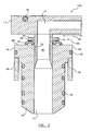
- Figure 1 is a sectional view of a portion of an injection molding system showing a sealing system according to an embodiment of the invention.
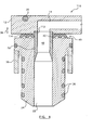
- Figure 2 is a sectional view of a portion of an injection molding system showing a sealing system according to a further embodiment of the invention.
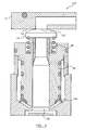
- Figure 3 is a sectional view of a portion of an injection molding system showing a sealing system according to another embodiment of the invention.
- Figure 4 is a sectional view of a portion of an injection molding system showing a sealing system according to another embodiment of the invention.
- Figure 5 is a sectional view of a portion of an injection molding system showing a sealing system according to another embodiment of the invention.
- Figure 6 is a sectional view of a portion of an injection molding system showing a sealing system according to another embodiment of the invention.
- Figure 1 shows, indicated generally by reference 10, a portion of an injection molding apparatus.
- Injection molding apparatus 10 includes a manifold 12 through which a manifold melt channel 14 passes.
- Manifold melt channel 14 is a conduit for a melt stream of moldable material that flows through manifold melt channel 14 in the direction indicated by arrows 16 and exits manifold melt channel 14 at a channel outlet 18.
- Manifold heaters 20 are provided in manifold 12 to maintain the melt stream at a desired temperature.
- a nozzle 24 is located between manifold 12 and a mold cavity (not shown).
- Nozzle 24 includes a nozzle melt channel 22 for receiving the melt stream from manifold melt channel 14 and delivering it to the mold cavity, typically through a mold gate (not shown) that is located adjacent a tip 26 of nozzle 24.
- Nozzle 24 is provided with a heater 28 for maintaining a desired melt stream heat profile as the melt stream passes through nozzle channel 22.
- Heater 28 could take a number of different configurations, including for example, a helical heating wire provided near or at an outer surface of nozzle 24, as shown in Figure 1. Although only a single nozzle is shown in Figure 1, the injection molding system 10 will typically include a plurality of such nozzles.
- Nozzle 24 is received within a nozzle cavity 32 in a cavity plate 30.
- the outer surface of nozzle 24 will generally be spaced apart from the inner surface of nozzle cavity 32.
- nozzle 24 includes an enlarged head portion 34 from which a flange or spacer element 36 extends to support nozzle 24 on cavity plate 30.
- the present invention provides a seal arrangement, indicated generally by 40, for preventing or reducing leakage of the melt stream that may otherwise occur at the transition between manifold 12 and nozzle 24.
- Seal arrangement 40 includes a cooperating seal 42 and a biasing element 44.
- Seal 42 is telescopically mounted to nozzle 24 and includes a tubular wall 52 that defines a seal melt channel 46 with an inlet 48 that communicates with manifold channel melt 14 for receiving the melt stream from the manifold channel, and an outlet 50 that communicates with nozzle channel 22 for delivering the melt stream into nozzle channel 22.
- tubular wall 52 A portion of tubular wall 52 is slidably received within and movable relative to an upper portion of nozzle channel 22.
- the outer surface of tubular wall 52 overlaps and cooperates sufficiently tightly with the inner surface of nozzle channel 22 that back flow leakage of the melt stream is impeded.
- seal melt channel 46 may taper outwards in the vicinity of outlet 50.
- Seal 42 includes an enlarged upper end that in the illustrated embodiment is a cylindrical ring 54 through which seal channel 46 passes and that extends radially outward from an upper end of tubular wall 52.
- Cylindrical ring 54 has a planar upper surface 56 that surrounds seal inlet 48 and which sealably engages a planar bottom surface of manifold 12 that surrounds outlet 18.
- Cylindrical ring 54 also has a lower planar surface 58 that surrounds tubular wall 52 and is in spaced opposition to an upper surface 60 of head portion 34 of nozzle 24.
- directional orientation terms such as “upper” and “lower” are used for explanatory purposes only, as the components in use may have other directional orientations.
- Biasing element 44 shown in Figure 1 is a spring or deflection ring that is located between opposed surfaces 58 and 60 and has an inverted "U" shaped arcuate cross-section. Biasing element 44 pushes downwards on nozzle 24, and also biases cylindrical ring 54 of seal 42 against manifold 12, providing a sealing force at the interface between seal 42 and manifold 12. Biasing element 44 is preferably pre-loaded so that the sealing force is provided both when the injection molding system is cold as well as when it is hot. Biasing element 44 can be made of various materials or material combinations as is suitable for the particular molding conditions. In one embodiment, biasing element 44 is made of a high thermally conductive material such as high strength steel, although other resilient metals and materials could be used.
- Biasing element 44 could have a number of alternative configurations and cross-sections. For example, it could have, among other configurations, a side-ways “V” shaped cross-section, a "C” shaped cross-section or an "O” shaped cross-section.
- nozzle 24 includes enlarged head portion 34 from which spacer element 36 extends to support nozzle 24 relative to cavity plate 30.
- spacer element 36 is a tubular wall that is separately formed from nozzle 24 and has opposite facing bearing ends, one of which engages an annular shoulder 62 provided around the bottom of enlarged head portion 34, and the other of which engages an annular shoulder 64 that is provided on cavity plate 30.
- Spacer element 36 is made from a material that has a different thermal conductivity than the material of nozzle 24.
- spacer element 36 may be a material such as titanium, titanium alloy, or ceramic, having a lower thermal conductivity than nozzle 24, which is typically made from a tool steel such as H13 or P20 steel, for example.
- spacer element 36 could be made from a material having a higher thermal conductivity, such as copper, beryllium copper, brass or some steels, than nozzle 24. The material selected for spacer element 36 will depend on the particular molding application.
- seal 42 moves relative to nozzle 24, with tubular wall 52 of seal 42 telescoping in and out of nozzle 24 as the relative locations of manifold 12 and nozzle 24 vary due to thermal expansion and contraction of the various components of apparatus 10.
- Biasing element 44 applies force to the upper end of seal 42, such that a sealing force is maintained between the upper surface of cylindrical ring 54 and the lower surface of manifold 12.
- Biasing element 44 is configured to resiliently deform without damage resulting to the injection mold system components, while maintaining an appropriate sealing force.
- the thermal conductivity of spacer element 36 is selected to compliment the operation of seal arrangement 40.
- spacer element 36 having a relatively low thermal conductivity compared to nozzle 24 may be desired such that the increased pressure applied to biasing element 44 as nozzle 24 heats up is less than what it would be if spacer element 36 were made of a material having the same or higher thermal conductivity than the nozzle 24.
- spacer element 36 may be integrally formed with and/or from the same material as nozzle 24.
- FIG 2 shows a further embodiment of an injection molding apparatus 80, which is similar in configuration and operation to injection molding apparatus 10 subject to the differences that will be apparent from the Figures and this description.
- apparatus 80 includes deflection or spring biasing element 44 for biasing seal 42 against manifold 12.
- biasing element 44 is an annular ring with an "O" shaped cross-section, but could be any number of spring configurations.
- nozzle 24 of apparatus 80 includes an annular spacer element 82 that is integrally formed with and of the same materials as head portion 34 of nozzle 24, rather than being a separately formed element having a different thermal conductivity.
- Nozzle 24 of apparatus 80 includes an annular slot or recess 88 provided in the head portion 34 around an upper end of nozzle channel 22.
- a tubular biasing element 84 that surrounds a portion of tubular wall 52 of seal 42 is received in slot 88.
- Tubular biasing element 84 includes bearing surfaces at its opposite ends, with one end bearing against biasing element 44, and the opposite end bearing against an annular support shoulder 90 provided at the end of slot 88.
- Tubular biasing element 84 may have a smaller outer circumference than the circumference defined by slot 88, providing a space 92 between the walls of tubular biasing element 84 and slot 88 that are parallel to the melt flow direction, allowing for some relative lateral movement during operation of apparatus 80.
- Tubular biasing element 84 is in some embodiments made of a material having a different thermal conductivity than the material of nozzle 24.
- tubular biasing element 84 may be from a material such as titanium, titanium alloy, or ceramic, having a lower thermal conductivity than nozzle 24.
- tubular biasing element 84 could be made from a material having a higher thermal conductivity, such as copper, beryllium copper, brass or some steels, than nozzle 24. The material selected for tubular biasing element 84 will depend on the particular molding application.
- tubular biasing element 84 and biasing element 44 act in serial cooperation to bias cylindrical ring 54 of seal 42 against manifold 12 with a sealing pressure from cold start through to normal operating temperatures.
- Tubular biasing element 84 and biasing element 44 each have different thermal and pressure response characteristics, allowing selection of a combination that permits a seal between manifold 12 and cylindrical ring 54 of seal 42 to be maintained across a range of pressure and temperature conditions.
- tubular biasing element 84 will be substantially relatively unaffected by changes in pressure, and will be of a material having a thermal conductivity less than the material of nozzle 24 so as to mitigate the range of pressures that biasing element 44 is subjected to during operation of apparatus 80.
- manifold 12 may be a floating manifold in which a spacing element located on a side of the manifold opposite nozzle 24 applies a biasing force on manifold 12 towards nozzle 24, as shown for example in U.S. Patent No. 5,125,827, which is herein incorporated by reference in its entirety.
- seal 42 is sealably pressured against manifold 12 and telescopically mounted relative to nozzle 24, in some embodiments the configuration could be inverted with the seal telescopically mounted for movement relative to the manifold, and sealably pressured against nozzle 24.
- FIGS 3 and 4 show injection molding apparatus, indicated generally by 100 and 110, according to further embodiments of the invention.
- injection molding apparatus 100 is similar in configuration and operation to injection molding apparatus 10 subject to the differences that will be apparent from the Figures and this description.
- seal arrangement 40 of apparatus 100 tubular wall 52 of seal 42 extends beyond an upper surface of annular ring 54 to engage manifold 12.
- the upper end of tubular wall 52 could be received within a corresponding annular slot provided in manifold 12.
- FIG. 4 shows an injection molding apparatus 110 that is similar in configuration and operation to injection molding apparatus 10 subject to the differences that will be apparent from the Figures and this description.
- seal arrangement 40 is a one piece, integrally formed spring bias element 114 and seal 42.
- An upper end 112 of the tubular wall 52 is received within an annular slot provided in manifold 12, such that an upper end of seal melt channel 46 overlaps with an outlet portion of manifold melt channel 14.
- Spring bias element 114 as illustrated has a plurality of integrally connected concentric rings, each having a "U” or "C” shaped cross-section.
- a number of different bias element configurations could be used, including, for example, concentric rings having "V" shaped cross-sections, such as is shown in U.S.
- spring bias element 114 bears directly on both manifold 12 and nozzle 24. In use, spring bias element 114 deforms to allow tubular wall 52 to move relative to nozzle 24 to compensate for changes in relative vertical locations of manifold 12 and nozzle 24.
- FIG 5 shows another embodiment of an injection molding apparatus 120, which is similar in configuration and operation to injection molding apparatus 10 subject to the differences that will be apparent from Figure 5 and this description.
- apparatus 120 includes deflection or spring biasing element 44 for biasing seal 42 against manifold 12.
- Biasing spring 44 may be any number of spring configurations as described above.
- biasing seal 42 of apparatus 120 has a non-flat or a non-planar upper surface 122. More particularly, upper surface 122 contains a spherical or a dome-like profile of a certain radius. In a further embodiment, upper surface 122 may have a conical profile. In the embodiment of the present invention shown in Figure 5, manifold 12 is shown in cold conditions to have a lower planar surface 124 that makes contact with upper surface 122 of biasing seal 42. However, the non-flat upper surface 122 of biasing seal 42 also provides advantages when the entire manifold 12 bends under certain critical injection molding operating conditions of high temperature and pressure.
- the required sealing force may vary between each of the plurality of nozzles 24 that are fluidly connected to the manifold because the manifold may develop a slightly convex and/or concave lower surface under the high temperature and pressure operating conditions.
- a different required sealing force may be required for each of the nozzles 24 in order to keep each of them in sealing contact with manifold 12 which is further accommodated by the non-planar upper surface 122 of biasing seal 42.
- apparatus 120 may contain a nozzle gate seal 126, shown in Figures 5 and 6, that limits the thermal expansion of nozzle 24 towards a mold gate 128.
- Nozzle gate seal 126 also provides an additional biasing element for the entire nozzle 24.
- Figure 6 shows another embodiment of an injection molding apparatus 130, which is similar in configuration and operation to injection molding apparatus 10 subject to the differences that will be apparent from Figure 6 and this description.
- apparatus 130 includes deflection or spring biasing element 44 for biasing seal 42 against manifold 12.
- Biasing spring 44 may be any number of spring configurations as described above.
- manifold 12 includes a manifold seal insert 132 located at each of the exits of the manifold melt channels at the interface with biasing seal 42 of each nozzle 24.
- biasing seal 42 of apparatus 130 has non-flat or non-planar upper surface 122. More particularly, upper surface 122 contains a spherical or a dome profile of a certain radius. Upper surface 122 may also have a conical profile.
- Manifold seal insert 132 has a lower non-flat or non-planar surface 134 that correspondingly engages upper surface 122 of biasing seal 42.
- spring biasing element 44 acts upon biasing seal 42 in both cold and hot conditions.
- Spring biasing element 44 keeps biasing seal 42 in permanent contact with manifold 12 through a wide range of operating conditions, including both cold or hot temperature conditions. Further, spring biasing element 44 prevents local leakage for each nozzle 24 that, due to the bending of manifold 12, may have a wider gap at the interface with manifold 12. Further, when a nozzle 24 has a wide gap at the interface with manifold 12, upper surface 122 of biasing seal 42 described in connection with Figures 5 and 6 and manifold seal insert 132 described in connection with Figure 6 provide additional security against leakage.
- biasing seal 42 acts only upon biasing seal 42 rather than the entire nozzle 24. Only the biasing seal 42 is biased against manifold 12 because biasing seal 42 is telescopic within nozzle melt channel 22 and therefore freely slides in the longitudinal direction with changing operating conditions.
Landscapes
- Engineering & Computer Science (AREA)
- Manufacturing & Machinery (AREA)
- Mechanical Engineering (AREA)
- Injection Moulding Of Plastics Or The Like (AREA)
- Moulds For Moulding Plastics Or The Like (AREA)
Applications Claiming Priority (2)
| Application Number | Priority Date | Filing Date | Title |
|---|---|---|---|
| US44669803P | 2003-02-12 | 2003-02-12 | |
| US446698P | 2003-02-12 |
Publications (3)
| Publication Number | Publication Date |
|---|---|
| EP1447199A2 true EP1447199A2 (fr) | 2004-08-18 |
| EP1447199A3 EP1447199A3 (fr) | 2005-10-05 |
| EP1447199B1 EP1447199B1 (fr) | 2013-04-10 |
Family
ID=32682469
Family Applications (1)
| Application Number | Title | Priority Date | Filing Date |
|---|---|---|---|
| EP04003158.5A Expired - Lifetime EP1447199B1 (fr) | 2003-02-12 | 2004-02-12 | Joint télescopique entre bloc de distribution et buse de moulage |
Country Status (5)
| Country | Link |
|---|---|
| US (1) | US7189071B2 (fr) |
| EP (1) | EP1447199B1 (fr) |
| JP (1) | JP2004243772A (fr) |
| CN (1) | CN1526537B (fr) |
| CA (1) | CA2457583A1 (fr) |
Cited By (3)
| Publication number | Priority date | Publication date | Assignee | Title |
|---|---|---|---|---|
| FR2892968A1 (fr) * | 2005-11-04 | 2007-05-11 | Creations Nivernaises E C N Sa | Dispositif d'injection-moulage d'une matiere thermoplastique |
| WO2010146124A1 (fr) * | 2009-06-17 | 2010-12-23 | Runipsys Europe | Buse et systeme d'injection de matiere thermoplastique |
| US8375579B2 (en) | 2008-12-09 | 2013-02-19 | Runipsys Europe | System for injecting a thermoplastic material |
Families Citing this family (28)
| Publication number | Priority date | Publication date | Assignee | Title |
|---|---|---|---|---|
| US20050074514A1 (en) * | 2003-10-02 | 2005-04-07 | Anderson Oliver B. | Zero cycle molding systems, methods and apparatuses for manufacturing dosage forms |
| US20080199554A1 (en) * | 2004-05-17 | 2008-08-21 | Husky Injection Molding Systems Ltd. | Method and apparatus for coupling melt conduits in a molding system and/or a runner system |
| KR100746555B1 (ko) * | 2005-11-04 | 2007-08-09 | 허남욱 | 플라스틱제품 성형용 열팽창 완충 확장메니폴드 |
| US7329118B2 (en) * | 2005-11-12 | 2008-02-12 | D-M-E Company | Nozzle and apparatus for injection molding |
| US7258541B2 (en) * | 2006-01-05 | 2007-08-21 | Rui Novo | Thermal expansion compensation support |
| US7462032B2 (en) * | 2006-06-15 | 2008-12-09 | Husky Injection Molding Systems Ltd. | Split sprue bar having a device for preventing leakage |
| US7614869B2 (en) * | 2007-05-08 | 2009-11-10 | Mold-Masters (2007) Limited | Manifold nozzle connection for an injection molding system |
| EP2293917B1 (fr) * | 2008-06-25 | 2012-09-05 | Husky Injection Molding Systems S.A. | Dispositif de secours destiné à être utilisé dans un appareil de distribution de coulée d un système de moulage par injection |
| US7775788B2 (en) * | 2008-08-05 | 2010-08-17 | Mold-Masters (2007) Limited | Melt transfer components for a stack molding system |
| US7845936B2 (en) * | 2009-01-21 | 2010-12-07 | Mold-Masters (2007) Limited | Sealing arrangement for an edge gated nozzle in an injection molding system |
| EP2228193B1 (fr) * | 2009-03-13 | 2012-08-08 | Hans Schreck | Dispositif de buse |
| US7874833B2 (en) * | 2009-05-03 | 2011-01-25 | Mold-Masters (2007) Limited | Injection molding runner apparatus having pressure seal |
| JP5350890B2 (ja) * | 2009-06-03 | 2013-11-27 | 本田技研工業株式会社 | 射出成形装置 |
| CN102470589A (zh) * | 2009-07-17 | 2012-05-23 | 赫斯基注塑系统有限公司 | 模块化分流板系统 |
| CN103282181B (zh) * | 2011-01-04 | 2015-07-15 | 赫斯基注塑系统有限公司 | 具有歧管延伸件和偏置组件的模具工具系统 |
| US8287272B1 (en) * | 2011-03-31 | 2012-10-16 | Dme Company Llc | Injection molding apparatus having a nozzle retaining clip |
| EP2718083B1 (fr) * | 2011-06-09 | 2017-07-12 | Husky Injection Molding Systems Ltd. | Ensemble résistant à l'usure pour mettre en contact des composants de système d'outil de moulage |
| CN102285071B (zh) * | 2011-08-25 | 2013-04-24 | 苏州同大模具有限公司 | 瓶盖注塑成型模具的机械密封机构 |
| KR101410016B1 (ko) | 2012-01-20 | 2014-06-27 | 주식회사 유도 | 열팽창 방지부재가 구비된 핫런너 시스템 |
| CN102672894B (zh) * | 2012-04-28 | 2015-04-29 | 深圳创维精密科技有限公司 | 热流道系统的热嘴安装结构 |
| KR101452133B1 (ko) * | 2013-09-09 | 2014-10-16 | 김혁중 | 열팽창 보상기구가 구비된 핫런너 장치 |
| CN103522495A (zh) * | 2013-09-29 | 2014-01-22 | 苏州好特斯模具有限公司 | 一种高强度热嘴挂台组件 |
| US9186830B2 (en) | 2013-12-11 | 2015-11-17 | Mold-Masters (2007) Limited | Drop-in hot runner system |
| US20150197049A1 (en) * | 2014-01-16 | 2015-07-16 | Otto Maenner Innovation Gmbh | Side gating hot runner nozzle and associated floating manifold seals |
| JP6547416B2 (ja) * | 2015-05-26 | 2019-07-24 | 日産自動車株式会社 | 射出成形用金型 |
| JP7095484B2 (ja) * | 2018-08-21 | 2022-07-05 | トヨタ自動車株式会社 | ホットランナー装置 |
| EP3725489B1 (fr) * | 2019-04-17 | 2022-01-26 | Mold-Masters (2007) Limited | Système de canal chauffant |
| CN119283303B (zh) * | 2024-08-28 | 2025-12-30 | 宁波拓普集团股份有限公司 | 一种歧管模块及二次注塑方法 |
Citations (1)
| Publication number | Priority date | Publication date | Assignee | Title |
|---|---|---|---|---|
| US5125827A (en) | 1990-07-27 | 1992-06-30 | Gellert Jobst U | Injection molding apparatus having an insulative and resilient spacer member |
Family Cites Families (42)
| Publication number | Priority date | Publication date | Assignee | Title |
|---|---|---|---|---|
| US3535742A (en) * | 1967-07-31 | 1970-10-27 | Paul Marcus | Molding apparatus valve and nozzle |
| US3491408A (en) * | 1967-10-13 | 1970-01-27 | Apl Corp | Valve adjuster and stop mechanism for an injection molding machine |
| US3812228A (en) * | 1969-07-17 | 1974-05-21 | Shell Oil Co | Injection molding of foamable thermoplastic polymers using a retractable hot runner |
| CA976314A (en) * | 1972-11-21 | 1975-10-21 | Jobst U. Gellert | Hot runner heater |
| CA1032317A (fr) * | 1975-04-10 | 1978-06-06 | Jobst U. Gellert | Mecanisme a opercule pour le moulage par injection |
| CA1153523A (fr) | 1980-05-08 | 1983-09-13 | Jobst U. Gellert | Tige fixe d'alimentation pour moulage a injection |
| CA1153524A (fr) * | 1980-10-15 | 1983-09-13 | Jobst U. Gellert | Mecanisme a double effet pour actionneur de soupape de moulage par injection |
| JPS57165795A (en) * | 1981-04-03 | 1982-10-12 | Hitachi Ltd | Method of constructing atomic power turbine supporting table |
| CA1190018A (fr) * | 1982-07-12 | 1985-07-09 | Jobst U. Gellert | Manchon pour pointeau de moulage par injection, et sa fabrication |
| CA1193818A (fr) * | 1983-03-24 | 1985-09-24 | Jobst U. Gellert | Systeme de moulage par injection avec commande hydraulique a raccordements alternes |
| US4588367A (en) * | 1984-07-16 | 1986-05-13 | Husky Injection Molding Systems Ltd. | Hot runner manifold for injection molding machine |
| US4682945A (en) * | 1984-07-16 | 1987-07-28 | Husky Injection Molding Systems Ltd. | Thermal insulating and expansion assembly for injection molding machine |
| FR2625133B1 (fr) * | 1987-12-24 | 1990-09-21 | Delta Projet | Buse de moule pour injection de matiere plastique |
| CA1266359A (fr) * | 1988-04-13 | 1990-03-06 | Harald H. Schmidt | Systeme de moulage par injection a buses tandem |
| US5032078A (en) * | 1988-07-11 | 1991-07-16 | Salvatore Benenati | Assembly of injection molding manifold, nozzles and mold |
| NL8802810A (nl) * | 1988-11-15 | 1990-06-01 | Eurotool Bv | Inspuitmondstuk voor toepassing bij een spuitgiet-inrichting. |
| CA2010855C (fr) | 1990-02-23 | 1999-07-27 | Jobst Ulrich Gellert | Systeme de moulage par injection avec ajutage a ressort de tension |
| JPH0694144B2 (ja) | 1990-07-09 | 1994-11-24 | 株式会社日本製鋼所 | 射出成形方法及び射出成形型 |
| US5374182A (en) * | 1992-09-30 | 1994-12-20 | Husky Injection Molding Systems Ltd. | Hot runner manifold bushing |
| US5478230A (en) * | 1994-04-13 | 1995-12-26 | Caco Pacific Corporation | Back-to-back valve gate system |
| US5499916A (en) * | 1994-10-28 | 1996-03-19 | Husky Injection Molding Systems Ltd. | Rotary actuated gate valve |
| US5609893A (en) | 1995-01-12 | 1997-03-11 | Jk Molds, Inc. | Probe assembly for injection molding apparatus |
| DE29501450U1 (de) * | 1995-01-31 | 1995-03-30 | Dipl.-Ing. Herbert Günther Gesellschaft mbH, Perchtoldsdorf | Heißkanaldüse |
| DE19601102C2 (de) | 1996-01-13 | 1999-04-15 | Psg Plastic Service Gmbh | Heißkanalsystem |
| JPH09277320A (ja) * | 1996-04-10 | 1997-10-28 | Otto Maenner | 射出成形型と協働するニードル閉鎖弁 |
| EP0806275A1 (fr) * | 1996-05-10 | 1997-11-12 | EUROTOOL Beheer B.V. | Système de moulage par injection et une pièce d'espacement |
| US5896640A (en) | 1996-11-12 | 1999-04-27 | Husky Injection Molding Systems Ltd. | Deflection sealing apparatus and method |
| JPH10166393A (ja) | 1996-12-16 | 1998-06-23 | Sekisui Chem Co Ltd | 射出成形用金型 |
| US6309207B1 (en) * | 1998-06-10 | 2001-10-30 | Husky Injection Molding Systems Ltd. | Injection molding nozzle assembly |
| US20010011415A1 (en) * | 1997-06-13 | 2001-08-09 | Jacek Kalemba | Injection molding nozzle assembly |
| US6062846A (en) * | 1997-06-13 | 2000-05-16 | Husky Injection Molding Systems, Ltd. | Injection molding nozzle assembly |
| JP3624688B2 (ja) * | 1998-04-23 | 2005-03-02 | 株式会社村田製作所 | 誘電体フィルタ、送受共用器および通信機 |
| US6261084B1 (en) * | 1998-08-28 | 2001-07-17 | Synventive Moldings Solutions Canada, Inc. | Elastically deformable nozzle for injection molding |
| US20010022321A1 (en) * | 1999-11-08 | 2001-09-20 | Abdeslam Bouti | Melt flow mixer in an injection molding system |
| ATE287305T1 (de) | 1999-11-15 | 2005-02-15 | Plasthing Srl | Giessform zum spritzgiessen von magnesium und seine legierungen |
| DE10008722B4 (de) | 2000-02-24 | 2010-02-11 | EWIKON Heißkanalsysteme GmbH & Co. KG | Verbindungselement |
| ITPN20000025A1 (it) | 2000-04-20 | 2001-10-20 | Sipa Spa | Ugello di iniezione di sostanza plastica |
| US6669462B1 (en) | 2000-05-19 | 2003-12-30 | Husk, Injection Molding Systems Ltd. | Hot runner sealing apparatus |
| US6368542B1 (en) * | 2000-06-15 | 2002-04-09 | D-M-E Company | Thermal expansion compensation support |
| IT1320639B1 (it) | 2000-09-13 | 2003-12-10 | Piero Enrietti | Testa riscaldata di alimentazione di un ugello di iniezione per lostampaggio di materiali plastici. |
| ITTO20010939A1 (it) | 2001-10-04 | 2003-04-04 | Attrezzature Speciali Srl As | ,,gruppo camera calda - iniettore per stampi di iniezione di materie plastiche,, |
| CA2474024A1 (fr) * | 2002-02-04 | 2003-08-14 | Mold-Masters Limited | Joint thermosoude entre un collecteur et une buse |
-
2004
- 2004-02-11 US US10/775,154 patent/US7189071B2/en not_active Expired - Lifetime
- 2004-02-12 CA CA002457583A patent/CA2457583A1/fr not_active Abandoned
- 2004-02-12 EP EP04003158.5A patent/EP1447199B1/fr not_active Expired - Lifetime
- 2004-02-12 JP JP2004035614A patent/JP2004243772A/ja not_active Withdrawn
- 2004-02-12 CN CN2004100074162A patent/CN1526537B/zh not_active Expired - Fee Related
Patent Citations (1)
| Publication number | Priority date | Publication date | Assignee | Title |
|---|---|---|---|---|
| US5125827A (en) | 1990-07-27 | 1992-06-30 | Gellert Jobst U | Injection molding apparatus having an insulative and resilient spacer member |
Cited By (8)
| Publication number | Priority date | Publication date | Assignee | Title |
|---|---|---|---|---|
| FR2892968A1 (fr) * | 2005-11-04 | 2007-05-11 | Creations Nivernaises E C N Sa | Dispositif d'injection-moulage d'une matiere thermoplastique |
| WO2007051857A3 (fr) * | 2005-11-04 | 2007-08-30 | Delachaux Sa | Dispositif d'injection-moulage d'une matière thermoplastique |
| US8375579B2 (en) | 2008-12-09 | 2013-02-19 | Runipsys Europe | System for injecting a thermoplastic material |
| WO2010146124A1 (fr) * | 2009-06-17 | 2010-12-23 | Runipsys Europe | Buse et systeme d'injection de matiere thermoplastique |
| FR2946914A1 (fr) * | 2009-06-17 | 2010-12-24 | Runipsys Europ | Buse et systeme d'injection de matiere thermoplastique |
| CN102458792A (zh) * | 2009-06-17 | 2012-05-16 | 瑞尼浦斯欧洲公司 | 用于注射热塑性材料的喷嘴和系统 |
| US8597019B2 (en) | 2009-06-17 | 2013-12-03 | Runipsys Europe | Nozzle and system for injecting thermoplastic material |
| CN102458792B (zh) * | 2009-06-17 | 2014-11-05 | 瑞尼浦斯欧洲公司 | 用于注射热塑性材料的喷嘴和系统 |
Also Published As
| Publication number | Publication date |
|---|---|
| EP1447199A3 (fr) | 2005-10-05 |
| CN1526537B (zh) | 2010-06-16 |
| CN1526537A (zh) | 2004-09-08 |
| US20040156944A1 (en) | 2004-08-12 |
| JP2004243772A (ja) | 2004-09-02 |
| CA2457583A1 (fr) | 2004-08-12 |
| EP1447199B1 (fr) | 2013-04-10 |
| US7189071B2 (en) | 2007-03-13 |
Similar Documents
| Publication | Publication Date | Title |
|---|---|---|
| US7189071B2 (en) | Telescopic manifold nozzle seal | |
| EP2228194B1 (fr) | Agencement d'étanchéité pour un diffuseur d'injection latérale dans un système de moulage par injection | |
| US7168941B2 (en) | Thermal seal between manifold and nozzle | |
| US7549855B2 (en) | Nozzle tip for high melt pressure applications | |
| US5896640A (en) | Deflection sealing apparatus and method | |
| EP2293917B1 (fr) | Dispositif de secours destiné à être utilisé dans un appareil de distribution de coulée d un système de moulage par injection | |
| EP0885707A1 (fr) | Assemblage de buse à mouler par injection | |
| EP1466715B1 (fr) | Buse à canal de chauffé avec étanchification de la matière fondue | |
| US6913266B2 (en) | Sealing device | |
| AU2001269808B2 (en) | Thermal expansion compensation support | |
| US7874833B2 (en) | Injection molding runner apparatus having pressure seal | |
| EP1663607B1 (fr) | Dispositif assurant une etancheite entre une buse d'injection a canaux chauffants et un collecteur | |
| EP1436133B1 (fr) | Joint place entre une buse et un composant moule dans un ensemble a canaux chauffants pour un appareil de moulage par injection | |
| JP4739844B2 (ja) | 燃料噴射系 | |
| US7396226B2 (en) | Nozzle sealing assembly | |
| US7258541B2 (en) | Thermal expansion compensation support | |
| US7381050B2 (en) | Snap on flange for injection molding nozzle | |
| KR20160004686A (ko) | 핫런너 시스템의 메탈 링을 갖는 노즐 | |
| EP2523065B1 (fr) | Soupape de régulation et procédé d'étalonnage d'une telle soupape de régulation |
Legal Events
| Date | Code | Title | Description |
|---|---|---|---|
| PUAI | Public reference made under article 153(3) epc to a published international application that has entered the european phase |
Free format text: ORIGINAL CODE: 0009012 |
|
| AK | Designated contracting states |
Kind code of ref document: A2 Designated state(s): AT BE BG CH CY CZ DE DK EE ES FI FR GB GR HU IE IT LI LU MC NL PT RO SE SI SK TR |
|
| AX | Request for extension of the european patent |
Extension state: AL LT LV MK |
|
| PUAL | Search report despatched |
Free format text: ORIGINAL CODE: 0009013 |
|
| AK | Designated contracting states |
Kind code of ref document: A3 Designated state(s): AT BE BG CH CY CZ DE DK EE ES FI FR GB GR HU IE IT LI LU MC NL PT RO SE SI SK TR |
|
| AX | Request for extension of the european patent |
Extension state: AL LT LV MK |
|
| 17P | Request for examination filed |
Effective date: 20060323 |
|
| AKX | Designation fees paid |
Designated state(s): DE IT |
|
| 17Q | First examination report despatched |
Effective date: 20070222 |
|
| RAP1 | Party data changed (applicant data changed or rights of an application transferred) |
Owner name: MOLD-MASTERS (2007) LIMITED |
|
| 111Z | Information provided on other rights and legal means of execution |
Free format text: DE IT Effective date: 20080425 |
|
| GRAP | Despatch of communication of intention to grant a patent |
Free format text: ORIGINAL CODE: EPIDOSNIGR1 |
|
| GRAP | Despatch of communication of intention to grant a patent |
Free format text: ORIGINAL CODE: EPIDOSNIGR1 |
|
| GRAS | Grant fee paid |
Free format text: ORIGINAL CODE: EPIDOSNIGR3 |
|
| GRAA | (expected) grant |
Free format text: ORIGINAL CODE: 0009210 |
|
| AK | Designated contracting states |
Kind code of ref document: B1 Designated state(s): DE IT |
|
| REG | Reference to a national code |
Ref country code: DE Ref legal event code: R096 Ref document number: 602004041630 Country of ref document: DE Effective date: 20130606 |
|
| PLBE | No opposition filed within time limit |
Free format text: ORIGINAL CODE: 0009261 |
|
| STAA | Information on the status of an ep patent application or granted ep patent |
Free format text: STATUS: NO OPPOSITION FILED WITHIN TIME LIMIT |
|
| PG25 | Lapsed in a contracting state [announced via postgrant information from national office to epo] |
Ref country code: IT Free format text: LAPSE BECAUSE OF FAILURE TO SUBMIT A TRANSLATION OF THE DESCRIPTION OR TO PAY THE FEE WITHIN THE PRESCRIBED TIME-LIMIT Effective date: 20130410 |
|
| 26N | No opposition filed |
Effective date: 20140113 |
|
| REG | Reference to a national code |
Ref country code: DE Ref legal event code: R097 Ref document number: 602004041630 Country of ref document: DE Effective date: 20140113 |
|
| PGFP | Annual fee paid to national office [announced via postgrant information from national office to epo] |
Ref country code: DE Payment date: 20180122 Year of fee payment: 15 |
|
| REG | Reference to a national code |
Ref country code: DE Ref legal event code: R119 Ref document number: 602004041630 Country of ref document: DE |
|
| PG25 | Lapsed in a contracting state [announced via postgrant information from national office to epo] |
Ref country code: DE Free format text: LAPSE BECAUSE OF NON-PAYMENT OF DUE FEES Effective date: 20190903 |