EP1447247A2 - Suspension à essieu rigide pour un véhicule - Google Patents
Suspension à essieu rigide pour un véhicule Download PDFInfo
- Publication number
- EP1447247A2 EP1447247A2 EP04002500A EP04002500A EP1447247A2 EP 1447247 A2 EP1447247 A2 EP 1447247A2 EP 04002500 A EP04002500 A EP 04002500A EP 04002500 A EP04002500 A EP 04002500A EP 1447247 A2 EP1447247 A2 EP 1447247A2
- Authority
- EP
- European Patent Office
- Prior art keywords
- function
- axle body
- frame
- axle
- rigid axle
- Prior art date
- Legal status (The legal status is an assumption and is not a legal conclusion. Google has not performed a legal analysis and makes no representation as to the accuracy of the status listed.)
- Granted
Links
Images


Classifications
-
- B—PERFORMING OPERATIONS; TRANSPORTING
- B60—VEHICLES IN GENERAL
- B60G—VEHICLE SUSPENSION ARRANGEMENTS
- B60G11/00—Resilient suspensions characterised by arrangement, location or kind of springs
- B60G11/26—Resilient suspensions characterised by arrangement, location or kind of springs having fluid springs only, e.g. hydropneumatic springs
- B60G11/27—Resilient suspensions characterised by arrangement, location or kind of springs having fluid springs only, e.g. hydropneumatic springs wherein the fluid is a gas
-
- B—PERFORMING OPERATIONS; TRANSPORTING
- B60—VEHICLES IN GENERAL
- B60G—VEHICLE SUSPENSION ARRANGEMENTS
- B60G9/00—Resilient suspensions of a rigid axle or axle housing for two or more wheels
- B60G9/003—Resilient suspensions of a rigid axle or axle housing for two or more wheels the axle being rigidly connected to a trailing guiding device
-
- B—PERFORMING OPERATIONS; TRANSPORTING
- B60—VEHICLES IN GENERAL
- B60G—VEHICLE SUSPENSION ARRANGEMENTS
- B60G2200/00—Indexing codes relating to suspension types
- B60G2200/30—Rigid axle suspensions
- B60G2200/31—Rigid axle suspensions with two trailing arms rigidly connected to the axle
-
- B—PERFORMING OPERATIONS; TRANSPORTING
- B60—VEHICLES IN GENERAL
- B60G—VEHICLE SUSPENSION ARRANGEMENTS
- B60G2200/00—Indexing codes relating to suspension types
- B60G2200/40—Indexing codes relating to the wheels in the suspensions
- B60G2200/44—Indexing codes relating to the wheels in the suspensions steerable
-
- B—PERFORMING OPERATIONS; TRANSPORTING
- B60—VEHICLES IN GENERAL
- B60G—VEHICLE SUSPENSION ARRANGEMENTS
- B60G2202/00—Indexing codes relating to the type of spring, damper or actuator
- B60G2202/10—Type of spring
- B60G2202/15—Fluid spring
- B60G2202/152—Pneumatic spring
Definitions
- the invention relates to a chassis of a commercial vehicle, in particular a truck, with Features of the type specified in the preamble of claim 1.
- the invention is based on DE 196 24 242 A1, which has the generic features disclosed.
- this known axis construction are for their longitudinal guidance and stabilization two upper trailing arms and below that a special anti-roll bar with trailing arms intended.
- This known axle pivot is comparatively complex in its entirety and expensive and also requires a lot of space in the commercial vehicle.
- This torsion beam is On each side of the axle, an air spring and a coaxial shock absorber Suspension strut supported against the commercial vehicle frame, for transverse steering ensures a specially connected Panhard rod.
- This well-known, technically extremely high Axle construction is for heavy commercial vehicles, especially trucks, designed for the highest because of their predominant field of use in long-distance traffic Driving comfort is a fundamental condition.
- To create front axle, including their suspension, damper, longitudinal and transverse guide and stabilizing elements are lightweight and space-saving as well Can be manufactured inexpensively and in the chassis in the area below a drive unit is easy to accommodate.
- the front axle construction according to the invention is simple due to the combination and inexpensive to manufacture components.
- the two trailing arms are as multi-functional organs designed because, in addition to their longitudinal guidance function, function is also important to them as a support element for the air spring and the shock absorber and as a connection element for one Stabilizer stamped, with one of the trailing arms also the function as Connection element for the Panhard rod.
- the fact that the U-shaped cross member on the frame side forms the connection element for the Panhard rod as well as for the two shock absorbers, stand-alone terminal blocks are not necessary for the latter - as is otherwise usual.
- the Avoids attachment and support of the air springs on the multi-function trailing arms also otherwise necessary connector blocks on the axle side and is extremely space-saving Solution.
- the solution according to the invention enables a conventional Rigid axle body can be used, which remains unchanged in other vehicles with other axle constructions and suspensions.
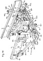
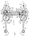
- this embodiment is the Front axle according to the invention in Fig. 1 A and 1 B in a perspective view obliquely from above with and without frame side members, in Fig. 2 in front view, in Fig. 3 in side view and shown in plan view in Fig. 4, where the frame side members are indicated only weakly lined are.
- Each of the two multi-function trailing arms 5, 6 lies on top of the rigid axle body 4 preferably fixed by means of several screw connections. It can in addition to this frictional connection also a positive connection between the underside of the first section 5/1, 6/1 of each multi-function trailing arm 5, 6 and the top or the The upper area on the rigid axle body 4 can be provided to ensure an absolutely secure fixed Ensure connection of these three components 4, 5, 6.
- the two multi-function trailing arms 5, 6 protrude with their first sections 5/1, 6/2 slightly beyond the rigid axle 4 and point to their given there free ends each an integrally molded or attached bearing 5/4, 6/4 for the attachment of the lower end of the shock absorber 9, 10 and next to a connection point 5/5, 6/5 for mounting a bearing bracket 20, 21 on that with a built-in Bearing includes the cross leg 12/3 of the U-shaped stabilizer 12.
- the one on a multi-function trailing arm 5, 6 starting from the first section 5/1, 6/1 downward to the plate-shaped support area 5/2, 6/2 extending transition area has an indentation 5/6 or 6/6 on the outside, into which the associated air spring 7 or 8 intervenes to save space without touching the wall.
- Each air spring 7, 8 has a piston 7% 1, 8/1, a top plate 7/2, 8/2 with eccentric 7/3, 8/3 and a self-welded connection bracket attached to it air bellows 7/4, 8/4 extending between the head plate and piston.
- Each air spring 7, 8 is with its piston 7/1, 8/1 on a pin 5/21, 6/21 on the support area 5/2, 6/2 of the associated Multi-function trailing arm 5, 6 supported and attached above with their headstock 7/2, 8/2 supported at the bottom on the associated frame side member 1, 2 and by means of the connection bracket flanged on the outside of the relevant frame side member 1, 2 7/3, 8/3 held in this mounting position.
- That multi-function trailing arm 5 or 6, which is the axle-side link for the Panhard rod 11, has an integrally molded one which projects upwards and laterally on the outside or attached bracket 22, between the two side walls of the Panhard rod 11 is received and stored with its axle bearing eye 11/1.
- the rigid axle body 4 has the known shape of a fist axis with cranked up Ends on, in the vertical or slightly sloping through holes Kingpin and associated bearings pivotally connect the axle beams of the wheels are.
- the rigid axle body 4 is designed to be largely rigid and torsionally rigid. Preferably is the rigid axle body 4, which also unchanged for other axes can be used.
- the two multi-function trailing arms 5, 6 in the area of their first sections 5/1, 6/1 and those mentioned above Transitional areas adjoining cranked support areas 5/2, 6/2 essentially designed to be resistant to bending and torsion.
- the guide arms connected to the latter 5/3, 6/3, on the other hand, are comparatively rigid only when viewed in the vertical direction, however designed to be twistable to a limited extent about its longitudinal axis and with regard to its flexural rigidity as well as torsional ability on the overall stabilization effect in connection with the stabilizer 12 coordinated by appropriate dimensioning and shaping of the relevant ones Cross-sections.
Landscapes
- Engineering & Computer Science (AREA)
- Mechanical Engineering (AREA)
- Vehicle Body Suspensions (AREA)
Applications Claiming Priority (2)
| Application Number | Priority Date | Filing Date | Title |
|---|---|---|---|
| AT0023303A AT412549B (de) | 2003-02-17 | 2003-02-17 | Fahrgestell eines nutzfahrzeuges, insbesondere lastkraftwagen |
| AT2332003 | 2003-02-17 |
Publications (3)
| Publication Number | Publication Date |
|---|---|
| EP1447247A2 true EP1447247A2 (fr) | 2004-08-18 |
| EP1447247A3 EP1447247A3 (fr) | 2006-05-24 |
| EP1447247B1 EP1447247B1 (fr) | 2011-04-13 |
Family
ID=32660438
Family Applications (1)
| Application Number | Title | Priority Date | Filing Date |
|---|---|---|---|
| EP04002500A Expired - Lifetime EP1447247B1 (fr) | 2003-02-17 | 2004-02-05 | Suspension à essieu rigide pour un véhicule |
Country Status (3)
| Country | Link |
|---|---|
| EP (1) | EP1447247B1 (fr) |
| AT (2) | AT412549B (fr) |
| DE (1) | DE502004012391D1 (fr) |
Cited By (3)
| Publication number | Priority date | Publication date | Assignee | Title |
|---|---|---|---|---|
| EP2382103A4 (fr) * | 2008-12-29 | 2012-05-30 | Volvo Lastvagnar Ab | Dispositif stabilisateur d'un essieu et stabilisateur |
| CN104401200A (zh) * | 2014-10-31 | 2015-03-11 | 北京新能源汽车股份有限公司 | 一种悬挂装置 |
| CN109050187A (zh) * | 2018-10-12 | 2018-12-21 | 核心驱动科技(金华)有限公司 | 商用车、独立悬架结构及悬架支撑臂 |
Citations (2)
| Publication number | Priority date | Publication date | Assignee | Title |
|---|---|---|---|---|
| DE19624242A1 (de) | 1996-06-18 | 1997-09-18 | Daimler Benz Ag | Vorrichtung zur Querführung einer Starrachse eines Kraftfahrzeuges |
| EP0940325B1 (fr) | 1998-03-04 | 2002-11-20 | MAN Nutzfahrzeuge Aktiengesellschaft | Chassis pour véhicule utilitaire lourd |
Family Cites Families (1)
| Publication number | Priority date | Publication date | Assignee | Title |
|---|---|---|---|---|
| FR2827814B1 (fr) * | 2001-07-27 | 2005-12-02 | Renault Vehicules Ind | Ensemble de suspension avant pneumatique pour vehicule industriel |
-
2003
- 2003-02-17 AT AT0023303A patent/AT412549B/de not_active IP Right Cessation
-
2004
- 2004-02-05 AT AT04002500T patent/ATE505348T1/de active
- 2004-02-05 EP EP04002500A patent/EP1447247B1/fr not_active Expired - Lifetime
- 2004-02-05 DE DE502004012391T patent/DE502004012391D1/de not_active Expired - Lifetime
Patent Citations (2)
| Publication number | Priority date | Publication date | Assignee | Title |
|---|---|---|---|---|
| DE19624242A1 (de) | 1996-06-18 | 1997-09-18 | Daimler Benz Ag | Vorrichtung zur Querführung einer Starrachse eines Kraftfahrzeuges |
| EP0940325B1 (fr) | 1998-03-04 | 2002-11-20 | MAN Nutzfahrzeuge Aktiengesellschaft | Chassis pour véhicule utilitaire lourd |
Cited By (4)
| Publication number | Priority date | Publication date | Assignee | Title |
|---|---|---|---|---|
| EP2382103A4 (fr) * | 2008-12-29 | 2012-05-30 | Volvo Lastvagnar Ab | Dispositif stabilisateur d'un essieu et stabilisateur |
| CN104401200A (zh) * | 2014-10-31 | 2015-03-11 | 北京新能源汽车股份有限公司 | 一种悬挂装置 |
| CN109050187A (zh) * | 2018-10-12 | 2018-12-21 | 核心驱动科技(金华)有限公司 | 商用车、独立悬架结构及悬架支撑臂 |
| CN109050187B (zh) * | 2018-10-12 | 2023-10-20 | 浙江盘毂动力科技有限公司 | 商用车、独立悬架结构及悬架支撑臂 |
Also Published As
| Publication number | Publication date |
|---|---|
| ATA2332003A (de) | 2004-09-15 |
| DE502004012391D1 (de) | 2011-05-26 |
| ATE505348T1 (de) | 2011-04-15 |
| EP1447247A3 (fr) | 2006-05-24 |
| EP1447247B1 (fr) | 2011-04-13 |
| AT412549B (de) | 2005-04-25 |
Similar Documents
| Publication | Publication Date | Title |
|---|---|---|
| DE19809209A1 (de) | Fahrgestell eines Frontlenker-Lastkraftwagen | |
| DE19605283B4 (de) | Längslenkeraufhängung für Fahrzeuge | |
| WO2008138451A1 (fr) | Essieu arrière pour véhicule à moteur | |
| EP0798198A1 (fr) | Palier avant pour la cabine basculante d'un camion | |
| EP0352541A1 (fr) | Suspension élastique d'essieu pour véhicules automobiles, notamment pour véhicules utilitaires | |
| EP0806310A2 (fr) | Suspension indépendante pour une roue directrice à suspension pneumatique d'un autobus ou camion | |
| DE10055859B4 (de) | Achskonstruktion für nichtangetriebene Fahrzeugachsen | |
| DE19809281A1 (de) | Fahrgestell eines schweren Nutzfahrzeuges | |
| EP0940319B1 (fr) | Chassis d'un véhicule utilitaire lourd | |
| DE4107303A1 (de) | Luftgefederte, lenkbare raeder tragende achse eines kraftfahrzeuges, insbesondere niederflurbus | |
| AT412549B (de) | Fahrgestell eines nutzfahrzeuges, insbesondere lastkraftwagen | |
| DE69304236T2 (de) | Radaufhängungsvorrichtung für einen lenkbaren Vorderradsatz eines Nutzfahrzeuges | |
| EP0940322B1 (fr) | Chassis pour véhicule utilitaire lourd | |
| EP0502311B1 (fr) | Essieu à roues directrices et à suspension pneumatique pour véhicule à moteur | |
| AT504976B1 (de) | Federfangvorrichtung | |
| EP0940324A1 (fr) | Chassis pour véhicule utilitaire lourd | |
| EP0940325A1 (fr) | Chassis pour véhicule utilitaire lourd | |
| EP0940323B1 (fr) | Chassis pour véhicule utilitaire lourd | |
| EP0940321B1 (fr) | Chassis pour véhicule utilitaire lourd | |
| AT413971B (de) | Gefederte aufhängung einer starrachse am fahrgestell-rahmen eines fahrzeugs, insbesondere lastkraftwagens oder omnibusses | |
| DE4107305C2 (de) | Luftgefederte, lenkbare Räder tragende Achse eines Kraftfahrzeuges | |
| AT501922B1 (de) | Nutzfahrzeug, insbesondere lastkraftwagen, mit spezieller aufhängung und lenkung zweier benachbarter vorderachsen | |
| AT405500B (de) | Luft- oder hydropneumatisch-gefederte starrachse eines lastkraftwagen oder omnibus | |
| AT407860B (de) | Aufhängung einer - insbesondere luftgefederten - hinterachse eines lastkraftwagens oder omnibusses | |
| DE102006023783A1 (de) | Achslastausgleichende Aufhängung zweier benachbarter Starrachsen am Rahmen einen Nutzfahrzeugs |
Legal Events
| Date | Code | Title | Description |
|---|---|---|---|
| PUAI | Public reference made under article 153(3) epc to a published international application that has entered the european phase |
Free format text: ORIGINAL CODE: 0009012 |
|
| AK | Designated contracting states |
Kind code of ref document: A2 Designated state(s): AT BE BG CH CY CZ DE DK EE ES FI FR GB GR HU IE IT LI LU MC NL PT RO SE SI SK TR |
|
| AX | Request for extension of the european patent |
Extension state: AL LT LV MK |
|
| RAP1 | Party data changed (applicant data changed or rights of an application transferred) |
Owner name: MAN NUTZFAHRZEUGE OESTERREICH AG |
|
| PUAL | Search report despatched |
Free format text: ORIGINAL CODE: 0009013 |
|
| AK | Designated contracting states |
Kind code of ref document: A3 Designated state(s): AT BE BG CH CY CZ DE DK EE ES FI FR GB GR HU IE IT LI LU MC NL PT RO SE SI SK TR |
|
| AX | Request for extension of the european patent |
Extension state: AL LT LV MK |
|
| 17P | Request for examination filed |
Effective date: 20060701 |
|
| AKX | Designation fees paid |
Designated state(s): AT DE FR IT NL SE |
|
| 17Q | First examination report despatched |
Effective date: 20080318 |
|
| GRAP | Despatch of communication of intention to grant a patent |
Free format text: ORIGINAL CODE: EPIDOSNIGR1 |
|
| GRAS | Grant fee paid |
Free format text: ORIGINAL CODE: EPIDOSNIGR3 |
|
| GRAA | (expected) grant |
Free format text: ORIGINAL CODE: 0009210 |
|
| AK | Designated contracting states |
Kind code of ref document: B1 Designated state(s): AT DE FR IT NL SE |
|
| REF | Corresponds to: |
Ref document number: 502004012391 Country of ref document: DE Date of ref document: 20110526 Kind code of ref document: P |
|
| REG | Reference to a national code |
Ref country code: DE Ref legal event code: R096 Ref document number: 502004012391 Country of ref document: DE Effective date: 20110526 |
|
| REG | Reference to a national code |
Ref country code: SE Ref legal event code: TRGR |
|
| REG | Reference to a national code |
Ref country code: NL Ref legal event code: T3 |
|
| PLBE | No opposition filed within time limit |
Free format text: ORIGINAL CODE: 0009261 |
|
| STAA | Information on the status of an ep patent application or granted ep patent |
Free format text: STATUS: NO OPPOSITION FILED WITHIN TIME LIMIT |
|
| RAP2 | Party data changed (patent owner data changed or rights of a patent transferred) |
Owner name: MAN TRUCK & BUS OESTERREICH AG |
|
| REG | Reference to a national code |
Ref country code: NL Ref legal event code: TD Effective date: 20120223 |
|
| REG | Reference to a national code |
Ref country code: DE Ref legal event code: R081 Ref document number: 502004012391 Country of ref document: DE Owner name: MAN TRUCK & BUS OESTERREICH AG, AT Free format text: FORMER OWNER: MAN NUTZFAHRZEUGE OESTERREICH AG, STEYR, AT Effective date: 20120125 Ref country code: DE Ref legal event code: R081 Ref document number: 502004012391 Country of ref document: DE Owner name: MAN TRUCK & BUS OESTERREICH AG, AT Free format text: FORMER OWNER: MAN STEYR AG, STEYR, AT Effective date: 20110317 |
|
| 26N | No opposition filed |
Effective date: 20120116 |
|
| REG | Reference to a national code |
Ref country code: DE Ref legal event code: R097 Ref document number: 502004012391 Country of ref document: DE Effective date: 20120116 |
|
| REG | Reference to a national code |
Ref country code: AT Ref legal event code: HC Ref document number: 505348 Country of ref document: AT Kind code of ref document: T Owner name: MAN TRUCK & BUS OESTERREICH AG, AT Effective date: 20120530 |
|
| REG | Reference to a national code |
Ref country code: FR Ref legal event code: PLFP Year of fee payment: 13 |
|
| REG | Reference to a national code |
Ref country code: FR Ref legal event code: PLFP Year of fee payment: 14 |
|
| REG | Reference to a national code |
Ref country code: FR Ref legal event code: PLFP Year of fee payment: 15 |
|
| REG | Reference to a national code |
Ref country code: DE Ref legal event code: R081 Ref document number: 502004012391 Country of ref document: DE Owner name: MAN TRUCK & BUS SE, DE Free format text: FORMER OWNER: MAN TRUCK & BUS OESTERREICH AG, STEYR, AT |
|
| REG | Reference to a national code |
Ref country code: AT Ref legal event code: PC Ref document number: 505348 Country of ref document: AT Kind code of ref document: T Owner name: MAN TRUCK & BUS SE, DE Effective date: 20211123 |
|
| PGFP | Annual fee paid to national office [announced via postgrant information from national office to epo] |
Ref country code: NL Payment date: 20230222 Year of fee payment: 20 |
|
| PGFP | Annual fee paid to national office [announced via postgrant information from national office to epo] |
Ref country code: FR Payment date: 20230223 Year of fee payment: 20 Ref country code: AT Payment date: 20230215 Year of fee payment: 20 |
|
| PGFP | Annual fee paid to national office [announced via postgrant information from national office to epo] |
Ref country code: SE Payment date: 20230222 Year of fee payment: 20 Ref country code: IT Payment date: 20230220 Year of fee payment: 20 Ref country code: DE Payment date: 20230227 Year of fee payment: 20 |
|
| REG | Reference to a national code |
Ref country code: NL Ref legal event code: PD Owner name: MAN TRUCK & BUS OESTERREICH GESMBH; AT Free format text: DETAILS ASSIGNMENT: CHANGE OF OWNER(S), ASSIGNMENT; FORMER OWNER NAME: MAN TRUCK & BUS OESTERREICH GESMBH Effective date: 20231031 |
|
| REG | Reference to a national code |
Ref country code: DE Ref legal event code: R071 Ref document number: 502004012391 Country of ref document: DE |
|
| REG | Reference to a national code |
Ref country code: NL Ref legal event code: MK Effective date: 20240204 |
|
| REG | Reference to a national code |
Ref country code: AT Ref legal event code: MK07 Ref document number: 505348 Country of ref document: AT Kind code of ref document: T Effective date: 20240205 |