EP1447306A2 - Servolenkung für Flurförderfahrzeug - Google Patents
Servolenkung für Flurförderfahrzeug Download PDFInfo
- Publication number
- EP1447306A2 EP1447306A2 EP04445009A EP04445009A EP1447306A2 EP 1447306 A2 EP1447306 A2 EP 1447306A2 EP 04445009 A EP04445009 A EP 04445009A EP 04445009 A EP04445009 A EP 04445009A EP 1447306 A2 EP1447306 A2 EP 1447306A2
- Authority
- EP
- European Patent Office
- Prior art keywords
- steering
- servo
- speed
- truck
- drive mode
- Prior art date
- Legal status (The legal status is an assumption and is not a legal conclusion. Google has not performed a legal analysis and makes no representation as to the accuracy of the status listed.)
- Withdrawn
Links
- 230000008859 change Effects 0.000 claims description 6
- 230000000875 corresponding effect Effects 0.000 description 7
- 230000008901 benefit Effects 0.000 description 4
- 230000005540 biological transmission Effects 0.000 description 2
- 230000009467 reduction Effects 0.000 description 2
- 238000009987 spinning Methods 0.000 description 2
- 230000000052 comparative effect Effects 0.000 description 1
- 230000001276 controlling effect Effects 0.000 description 1
- 230000002596 correlated effect Effects 0.000 description 1
- 230000008878 coupling Effects 0.000 description 1
- 238000010168 coupling process Methods 0.000 description 1
- 238000005859 coupling reaction Methods 0.000 description 1
- 238000001514 detection method Methods 0.000 description 1
- 230000006698 induction Effects 0.000 description 1
- 238000012423 maintenance Methods 0.000 description 1
- 238000004519 manufacturing process Methods 0.000 description 1
- 230000000717 retained effect Effects 0.000 description 1
- 230000001360 synchronised effect Effects 0.000 description 1
Images
Classifications
-
- B—PERFORMING OPERATIONS; TRANSPORTING
- B66—HOISTING; LIFTING; HAULING
- B66F—HOISTING, LIFTING, HAULING OR PUSHING, NOT OTHERWISE PROVIDED FOR, e.g. DEVICES WHICH APPLY A LIFTING OR PUSHING FORCE DIRECTLY TO THE SURFACE OF A LOAD
- B66F9/00—Devices for lifting or lowering bulky or heavy goods for loading or unloading purposes
- B66F9/06—Devices for lifting or lowering bulky or heavy goods for loading or unloading purposes movable, with their loads, on wheels or the like, e.g. fork-lift trucks
- B66F9/075—Constructional features or details
- B66F9/07568—Steering arrangements
-
- B—PERFORMING OPERATIONS; TRANSPORTING
- B62—LAND VEHICLES FOR TRAVELLING OTHERWISE THAN ON RAILS
- B62D—MOTOR VEHICLES; TRAILERS
- B62D5/00—Power-assisted or power-driven steering
- B62D5/04—Power-assisted or power-driven steering electrical, e.g. using an electric servo-motor connected to, or forming part of, the steering gear
- B62D5/0418—Electric motor acting on road wheel carriers
-
- B—PERFORMING OPERATIONS; TRANSPORTING
- B62—LAND VEHICLES FOR TRAVELLING OTHERWISE THAN ON RAILS
- B62D—MOTOR VEHICLES; TRAILERS
- B62D6/00—Arrangements for automatically controlling steering depending on driving conditions sensed and responded to, e.g. control circuits
- B62D6/002—Arrangements for automatically controlling steering depending on driving conditions sensed and responded to, e.g. control circuits computing target steering angles for front or rear wheels
-
- B—PERFORMING OPERATIONS; TRANSPORTING
- B62—LAND VEHICLES FOR TRAVELLING OTHERWISE THAN ON RAILS
- B62D—MOTOR VEHICLES; TRAILERS
- B62D6/00—Arrangements for automatically controlling steering depending on driving conditions sensed and responded to, e.g. control circuits
- B62D6/02—Arrangements for automatically controlling steering depending on driving conditions sensed and responded to, e.g. control circuits responsive only to vehicle speed
Definitions
- Position steering provides in particular a possibility to balance the steering influencing forces caused by the drive force transfer. If the driver steers straight forward the truck goes straight forward, he does not have to sit and compensate in any way.
- the object of the invention is to eliminate the drawbacks resulting from the use of position servo, but with a retaining of its advantages.
- this object can be solved by the steering being so arranged that when for instance the steering wheel rotate faster than the maximally allowed corresponding pivot speed of the servo the steering ceases working in position servo mode and starts to work as so called speed servo, that is the speed with which the steering wheel is turned instead of a position indicates the desired speed in the pivot or turning movement.
- speed servo the speed with which the steering wheel is turned instead of a position indicates the desired speed in the pivot or turning movement.
- the limit value of the speed of the steering wheel or control movement at which the truck change from being position servo controlled to speed servo controlled need not to be the same as the highest speed of the steering servo but may be lower, depending on what will provide the best safety or comfort for the driver.
- the shifting between position servo mode and speed servo mode may be controlled both by the truck speed and the control or steering wheel speed as well as by other parameters, as for instance load and lift height.
- Other parameters as for instance load and lift height.
- the desired result is achieved by limiting the deviation between is-value and target-value.
- each position of the control means corresponds to a respective position of the steered wheel. If the driver spins the steering wheel faster than the servo can cope with the difference between the corresponding positions become large and a disturbing delay result as has been described above.
- target value that is the steering wheel position
- is-value that is the steered wheel angle
- This limiting may for instance be achieved by correcting the difference between is-value and target value through subtraction or adding with a measure reducing the difference to such a level that the delay is not disturbing and perhaps not even noticed. If similar detection is used for steering servo and steering wheel it is only necessary to look at the difference measured in the number of pulses.
- the servo works as a conventional position servo with a delay so small that it is hardly noticed. If the driver executes a movement with the steering wheel that is so fast that the deviation becomes larger than the given angle the registered and thereby to the motor controlling part of the servo control delivered target value plus the maximally allowed angle deviation. When the driver stops rapidly spinning the wheel the deviation between the real is- and target values is reduced so that it gets within the given angle and the servo functions entirely as a non-manipulated position servo. If the rapid movement suddenly stops also the movement stops very fast corresponding to the given limited angle between is-value and target value.
- the limitation of the deviation between is- and target value can be executed entirely by software.
- the limitation can however also be made by hardware or even by applying a braking torque to the steering wheel that is braked by means of a motor in order to keep the deviation between is- and target value within a given measure so that the driver can not spin the steering wheel faster than corresponding to the permitted angle difference.
- the decided maximal deviation can be dimensioned so that it corresponds to the maximum speed of the control servo for changing steering angle.
- the object of the invention is therefor also to enable the equipping of smaller trucks with position servo steering by achieving a simple reliable and exact position sensing for the steering at a low cost.
- the steering servo comprising a brushless machine or motor of the type that contains sensors for the rotor position. These sensors are via a control unit used to control the rotating field that is generated in a stator in the motor to turn the rotor of the motor in the direction of rotation.
- the signals from these sensors are in accordance with the invention used as a measure of the rotation. Since the rotor rotates many revolutions at the achieving of a comparative small steering angle change for the driving wheel the use of such a machine and its anyhow existing sensors eliminates the cost of an additional steering angle sensor.
- this type of motor also other advantages for instance reduced maintenance and fouling are achieved since no brushes have to be changed.
- motors induction motors, permanent magnet rotors, asynchronous motors of AC-type as well as DC-type
- motors normally include three sensors located in an appropriate manner so that they together with the poles of the rotor give a number of signal pulses per steering revolution and this enables a very exact measure of the existing steering angle change.
- the turning of existing control means for instance a steering wheel defines exactly how much the wheel is to be steered in one or the other direction and turning is continued until a corresponding number of pulses have been counted.
- the steered driving wheel can be pivoted freely that is more than 360°, and with retained drive direction of the motor.
- the steering means can have a defined position in relation to a defined angle position of the steering wheel, for instance the position for driving straight forward the steering control and the measuring of the steering angle of the wheel must be zeroed and correlated.
- This extra sensor may be arranged in a suitable place and of in principle any kind at all provided that the accuracy is sufficient.
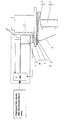
- the drive unit includes a wheel 7, a transmission 9 and a drive motor 10.
- a steering servo motor 3 is arranged that via a steering gear 4 and a small cogwheel 6 can work on a larger cogwheel 5, that is non-turnably fastened to the drive unit.
- the servo motor is further provided with a an electronic unit 8 to which is connected a sensor, not shown, for instance in the shape of a steering wheel with position or angle sensor.
- a reference sensor 1 fastened in the truck frame senses the position of a cam profile that is arranged fixed on the big cogwheel 5.
- the reference sensor 1 can for instance detect when the cam profile has reached a certain height. Initially, that is after fabrication or when the truck has been out of power a steering movement is carried out so that the intended reference position of the cam profile in relation to the reference detector is achieved or passed.
- the counting of pulses from a pulse emitter integrated in the servo motor is set to zero and the system is calibrated, in the electronic unit furthermore the exact number of servo motor pulses from the reference position to for instance the position straight forward may be counted etc.
- the reference detector may also start from if its value, (distance to the cam) is being reduced or increased in order to know in which direction turning takes place.
- a permanently magnetized synchronous machine with 2 or 3 pair of poles deliver 12 or 18 pulses per motor revolution to its control unit.
- This together with the gear reduction of the steering gear 4 and the cogs 5 and 6 provide a sufficiently good resolution for the position accuracy of the steered wheel.
- the signals obtained from the inner position detectors can within the scope of the inventive thought be considered to be replaced with signals or data of the rotational position of the motor obtained in other ways, for instance calculated from measured instantaneous current and/or voltage values.
- the truck can be programmed after a loss of electric power automatically to conduct a calibration through a turning of the transmission unit so that the reference position is achieved. Calibration can also take place every time that the reference detector is passed, which reduce the risk of electrical interference giving erroneous calculations and settings.
Landscapes
- Engineering & Computer Science (AREA)
- Transportation (AREA)
- Mechanical Engineering (AREA)
- Combustion & Propulsion (AREA)
- Chemical & Material Sciences (AREA)
- Structural Engineering (AREA)
- Geology (AREA)
- Life Sciences & Earth Sciences (AREA)
- Civil Engineering (AREA)
- Physics & Mathematics (AREA)
- Mathematical Physics (AREA)
- Control Of Position, Course, Altitude, Or Attitude Of Moving Bodies (AREA)
- Guiding Agricultural Machines (AREA)
- Steering Control In Accordance With Driving Conditions (AREA)
Applications Claiming Priority (4)
| Application Number | Priority Date | Filing Date | Title |
|---|---|---|---|
| SE0300307A SE524955C2 (sv) | 2003-02-06 | 2003-02-06 | Anordning vid truck med elmotorservo innefattande inre positionsavkännare |
| SE0300307 | 2003-02-06 | ||
| SE0300308A SE524881C2 (sv) | 2003-02-06 | 2003-02-06 | Servostyrning för truck som innefattar ett första och ett andra driftsfall |
| SE0300308 | 2003-02-06 |
Publications (2)
| Publication Number | Publication Date |
|---|---|
| EP1447306A2 true EP1447306A2 (de) | 2004-08-18 |
| EP1447306A3 EP1447306A3 (de) | 2004-12-01 |
Family
ID=32684369
Family Applications (1)
| Application Number | Title | Priority Date | Filing Date |
|---|---|---|---|
| EP04445009A Withdrawn EP1447306A3 (de) | 2003-02-06 | 2004-02-05 | Servolenkung für Flurförderfahrzeug |
Country Status (1)
| Country | Link |
|---|---|
| EP (1) | EP1447306A3 (de) |
Cited By (9)
| Publication number | Priority date | Publication date | Assignee | Title |
|---|---|---|---|---|
| EP1594026A3 (de) * | 2004-05-04 | 2007-01-17 | Liebherr-Werk Nenzing GmbH | Telelader, insbesondere Reachstacker, mit Lenkbefehleingabeeinrichtung |
| EP1972482A2 (de) | 2007-03-20 | 2008-09-24 | Gebr. Frei GmbH & Co. KG | Lenkantriebssystem |
| EP1873039A3 (de) * | 2006-06-28 | 2008-10-22 | Jungheinrich Aktiengesellschaft | Verfahren zur Einstellung eines Lenkbereichs bei einer elektrischen Lenkung für ein Flurförderzeug |
| EP2335962A1 (de) * | 2009-12-16 | 2011-06-22 | ZF Friedrichshafen AG | Antriebseinheit eines Flurförderzeugs |
| EP2244966B1 (de) * | 2008-02-05 | 2014-11-05 | Crown Equipment Corporation | Materialhandhabungsfahrzeug mit einem modul, das ein verhältnis von einem lenkbaren rad zur steuergriffposition ändern kann |
| CN104554424A (zh) * | 2013-10-21 | 2015-04-29 | 安吉华叉车辆有限公司 | 一种平衡堆高车的电子转向系统 |
| EP3042828A4 (de) * | 2013-09-02 | 2017-04-19 | Doosan Corporation | Vorrichtung zur steuerung eines lenkrads und verfahren zur steuerung eines lenkrads damit |
| CN110758548A (zh) * | 2018-07-27 | 2020-02-07 | 比亚迪股份有限公司 | 转向助力控制方法、车辆、服务器、存储介质及系统 |
| DE102006035863B4 (de) | 2006-08-01 | 2022-07-21 | Linde Material Handling Gmbh | Lenkvorrichtung für ein Flurförderzeug |
Citations (1)
| Publication number | Priority date | Publication date | Assignee | Title |
|---|---|---|---|---|
| WO2002040336A1 (de) * | 2000-11-18 | 2002-05-23 | Robert Bosch Gmbh | Kupplung für eine steer-by-wire-lenkanlage |
Family Cites Families (3)
| Publication number | Priority date | Publication date | Assignee | Title |
|---|---|---|---|---|
| US5181173A (en) * | 1991-07-23 | 1993-01-19 | Raymond Corporation | Variable ratio steering system for a motor vehicle |
| US6542801B2 (en) * | 2000-12-26 | 2003-04-01 | Nippon Yusoki Co., Ltd. | Power steering system |
| CA2396349C (en) * | 2001-08-02 | 2006-01-24 | Kabushiki Kaisha Toyota Jidoshokki | Steering wheel position compensating apparatus in steering apparatus |
-
2004
- 2004-02-05 EP EP04445009A patent/EP1447306A3/de not_active Withdrawn
Patent Citations (1)
| Publication number | Priority date | Publication date | Assignee | Title |
|---|---|---|---|---|
| WO2002040336A1 (de) * | 2000-11-18 | 2002-05-23 | Robert Bosch Gmbh | Kupplung für eine steer-by-wire-lenkanlage |
Cited By (13)
| Publication number | Priority date | Publication date | Assignee | Title |
|---|---|---|---|---|
| US7516813B2 (en) | 2004-05-04 | 2009-04-14 | Liebherr-Werk Nenzing Gmbh | Telescopic loader, in particular a reach stacker |
| EP1594026A3 (de) * | 2004-05-04 | 2007-01-17 | Liebherr-Werk Nenzing GmbH | Telelader, insbesondere Reachstacker, mit Lenkbefehleingabeeinrichtung |
| CN101104417B (zh) * | 2006-06-28 | 2012-05-30 | 容海因里希股份公司 | 用于调节地面输送工具的电转向器的转向区域的方法 |
| EP1873039A3 (de) * | 2006-06-28 | 2008-10-22 | Jungheinrich Aktiengesellschaft | Verfahren zur Einstellung eines Lenkbereichs bei einer elektrischen Lenkung für ein Flurförderzeug |
| DE102006035863B4 (de) | 2006-08-01 | 2022-07-21 | Linde Material Handling Gmbh | Lenkvorrichtung für ein Flurförderzeug |
| EP1972482A3 (de) * | 2007-03-20 | 2009-09-02 | Gebr. Frei GmbH & Co. KG | Lenkantriebssystem |
| EP1972482A2 (de) | 2007-03-20 | 2008-09-24 | Gebr. Frei GmbH & Co. KG | Lenkantriebssystem |
| EP2244966B1 (de) * | 2008-02-05 | 2014-11-05 | Crown Equipment Corporation | Materialhandhabungsfahrzeug mit einem modul, das ein verhältnis von einem lenkbaren rad zur steuergriffposition ändern kann |
| EP2335962A1 (de) * | 2009-12-16 | 2011-06-22 | ZF Friedrichshafen AG | Antriebseinheit eines Flurförderzeugs |
| EP3042828A4 (de) * | 2013-09-02 | 2017-04-19 | Doosan Corporation | Vorrichtung zur steuerung eines lenkrads und verfahren zur steuerung eines lenkrads damit |
| US9802647B2 (en) | 2013-09-02 | 2017-10-31 | Doosan Corporation | Device for controlling steering wheel and method for controlling steering wheel using same |
| CN104554424A (zh) * | 2013-10-21 | 2015-04-29 | 安吉华叉车辆有限公司 | 一种平衡堆高车的电子转向系统 |
| CN110758548A (zh) * | 2018-07-27 | 2020-02-07 | 比亚迪股份有限公司 | 转向助力控制方法、车辆、服务器、存储介质及系统 |
Also Published As
| Publication number | Publication date |
|---|---|
| EP1447306A3 (de) | 2004-12-01 |
Similar Documents
| Publication | Publication Date | Title |
|---|---|---|
| JP3789791B2 (ja) | 絶対位置検出装置及び絶対位置検出方法 | |
| JP2638583B2 (ja) | 電流コマンドに対する二次元補間法を用いた電気アシスト・ステアリング・システムの制御方法及び装置 | |
| EP1447306A2 (de) | Servolenkung für Flurförderfahrzeug | |
| EP0873587B1 (de) | Motorantriebsregelung | |
| US9010201B2 (en) | Measurement apparatus and method | |
| KR890003748B1 (ko) | 조타핸들의 조작타각 검출장치를 가지는 파워 스티어링 제어장치 | |
| KR100701046B1 (ko) | 파워 스티어링 시스템 | |
| KR20060073960A (ko) | 조향각 센서 | |
| KR20130063214A (ko) | 스티어링 칼럼의 비틀림을 측정하기 위한 토크센서 및 이를 이용한 측정방법 | |
| CN108698640A (zh) | 通过电动助力辅助转向设备中的适当的角度传感器/扭矩传感器磁体布置实现的波动最小化 | |
| JP4281595B2 (ja) | 角度検出装置 | |
| JP5092510B2 (ja) | 絶対舵角検出装置 | |
| US7087889B2 (en) | Rotational angle detecting apparatus and torque detecting apparatus | |
| GB2117521A (en) | Rotation detecting apparatus | |
| US7325646B2 (en) | Electric power steering apparatus | |
| GB2443525A (en) | Operation of an angular position sensor in an electrically assisted power steering system | |
| TWI719224B (zh) | 位置偵測裝置 | |
| KR101888480B1 (ko) | 복합형 토오크센서 | |
| KR100767185B1 (ko) | 차량의 조향각 보정 장치 및 방법 | |
| JP2005172720A (ja) | モータエンコーダ | |
| JP4900166B2 (ja) | 車両用操舵装置 | |
| JP3841674B2 (ja) | 車両の操舵装置 | |
| US20040041677A1 (en) | Dual resolver device | |
| GB2421717A (en) | Electronic control power steering device | |
| JP5950459B2 (ja) | パワーステアリング装置 |
Legal Events
| Date | Code | Title | Description |
|---|---|---|---|
| PUAI | Public reference made under article 153(3) epc to a published international application that has entered the european phase |
Free format text: ORIGINAL CODE: 0009012 |
|
| AK | Designated contracting states |
Kind code of ref document: A2 Designated state(s): AT BE BG CH CY CZ DE DK EE ES FI FR GB GR HU IE IT LI LU MC NL PT RO SE SI SK TR |
|
| AX | Request for extension of the european patent |
Extension state: AL LT LV MK |
|
| PUAL | Search report despatched |
Free format text: ORIGINAL CODE: 0009013 |
|
| AK | Designated contracting states |
Kind code of ref document: A3 Designated state(s): AT BE BG CH CY CZ DE DK EE ES FI FR GB GR HU IE IT LI LU MC NL PT RO SE SI SK TR |
|
| AX | Request for extension of the european patent |
Extension state: AL LT LV MK |
|
| 17P | Request for examination filed |
Effective date: 20050601 |
|
| AKX | Designation fees paid |
Designated state(s): AT BE BG CH CY CZ DE DK EE ES FI FR GB GR HU IE IT LI LU MC NL PT RO SE SI SK TR |
|
| 17Q | First examination report despatched |
Effective date: 20050913 |
|
| STAA | Information on the status of an ep patent application or granted ep patent |
Free format text: STATUS: THE APPLICATION IS DEEMED TO BE WITHDRAWN |
|
| 18D | Application deemed to be withdrawn |
Effective date: 20071127 |